Skyforge rendering technology

Hello! My name is Sergey Makeev, and I am the Technical Director in the Skyforge project in the Allods Team, the game studio Mail.Ru Group. I would like to tell you about rendering technologies that we use to create graphics in Skyforge. I'll tell you a little about the tasks that we faced when developing Skyforge from the point of view of a programmer. We have our own engine. Developing your technology is expensive and difficult, but the fact is that at the time of launching the game (three years ago) there was no technology that could satisfy all our needs. And we had to create the engine from scratch.
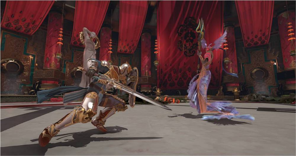
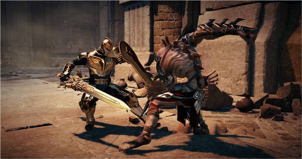
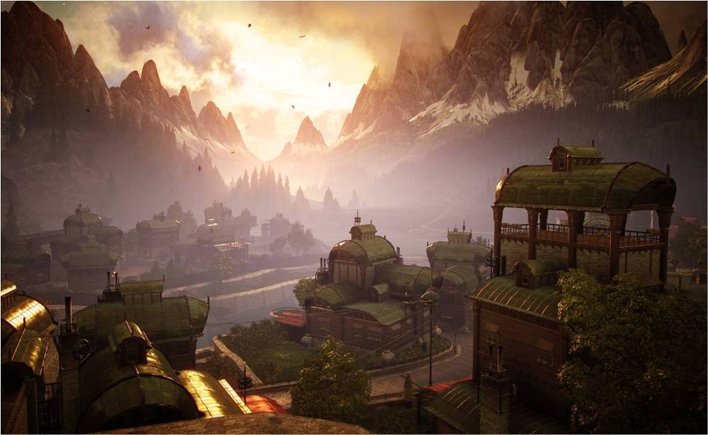
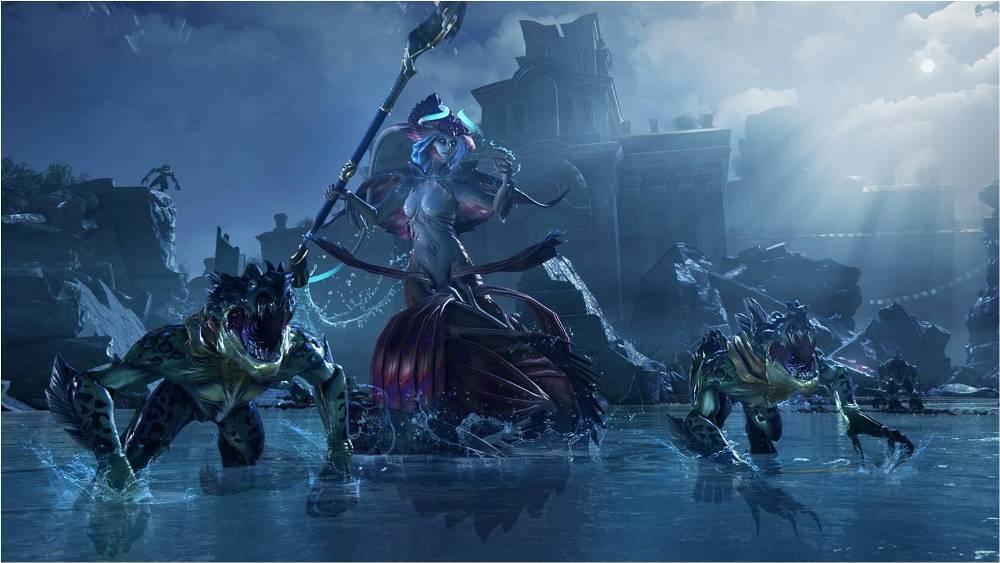
The main art-style game is a mixture of fantasy with Sci-Fi. To realize the ideas of the art director and artists, we needed to create a very strong, powerful system of materials. The player can see the manifestations of magic, technology and natural phenomena, and the system of materials is needed to plausibly draw all this on the screen. Another “pillar” of our graphic style is that we create a stylized reality. That is, objects are recognizable and look realistic, but this is not photorealism from life. A good example, in my opinion, is the film Avatar. Reality, but reality is artistically embellished, reality and at the same time a fairy tale. The next pillar of the graphic style - lighting and materials - look as natural as possible. And "naturally" from the point of view of a programmer - this means "physically."
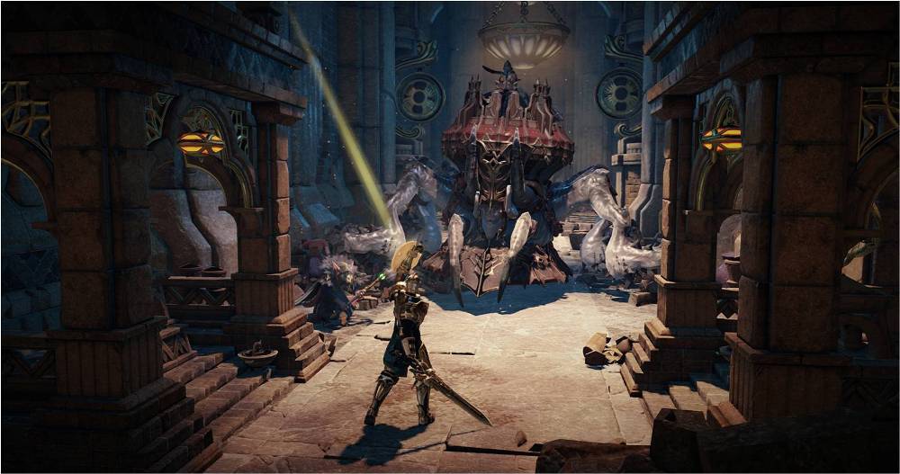
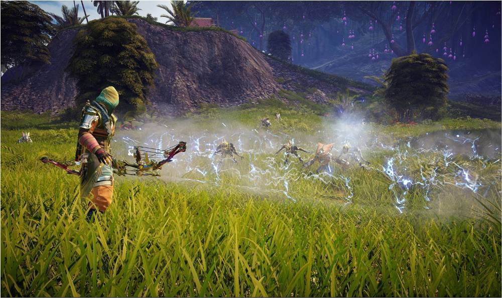
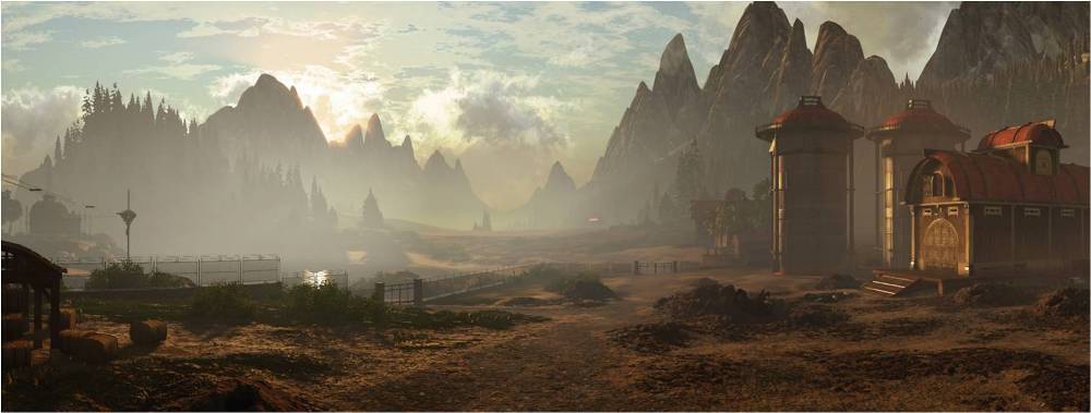
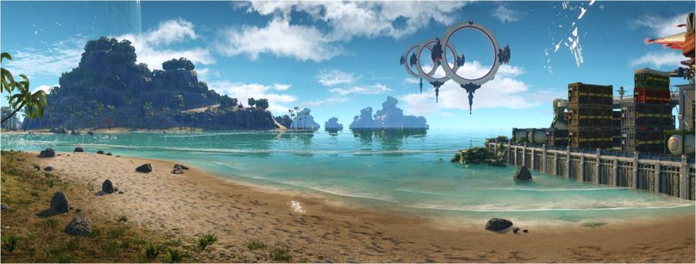
An important point for a programmer: we need huge open spaces. In the game there are both small locations-instansy, and huge areas in which there are many players. In this video you can see what we have achieved at the moment. Everything that is shown in the video is rendered using the game in the maximum settings.
')
Next, I will talk about how we have achieved such a picture.
Physically based shading (shading based on the laws of physics)
Why do we need shading based on physics?
- This gives us a more realistic and detailed picture. 3D models made by different artists look holistic in different types of lighting. The picture is less falling apart, and lighting artists do not need to mix all the lighting options with all the 3D models.
- Materials can be customized separately from light. That is, material artists and light artists can work in parallel. Correctly tuned physical materials in any light look as expected, do not suddenly become black and overexposed, as it often happened before, with non-physical materials.
- The parameters of the material has become less, and they all have a physical meaning. It is easier for artists to navigate these parameters. Of course, first they have to relearn, but then the work becomes much more predictable.
- Compliance with the law of conservation of energy in the system of materials means that it is easier for lighting designers to work. You can not, setting up the light, "scatter" the image into pieces.
- By the way, physical correctness does not commit us to photorealism. For example, all the latest cartoons created by Pixar and Disney Studios are made using a physical render. But at the same time there is no photorealism, but there is quite recognizable stylization.
Process physics
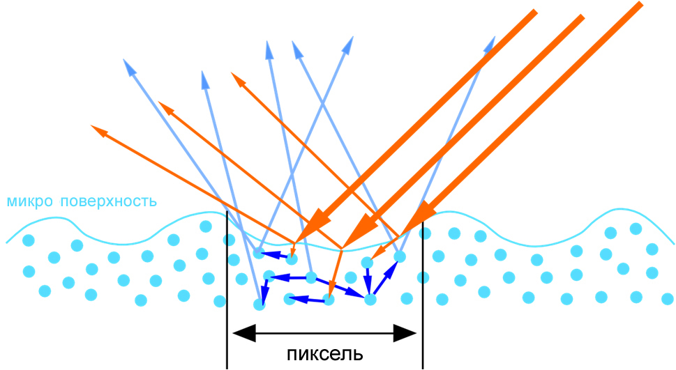
Before programming anything, you must first understand the physics of the process. What happens when light reflects off the surface? In real life, unlike computer graphics, the surfaces are not smooth, but in fact consist of many small irregularities. These irregularities are so small that their eyes are not visible. However, they are large enough to affect light reflected from the surface. Here in the picture I called it a micro-surface.

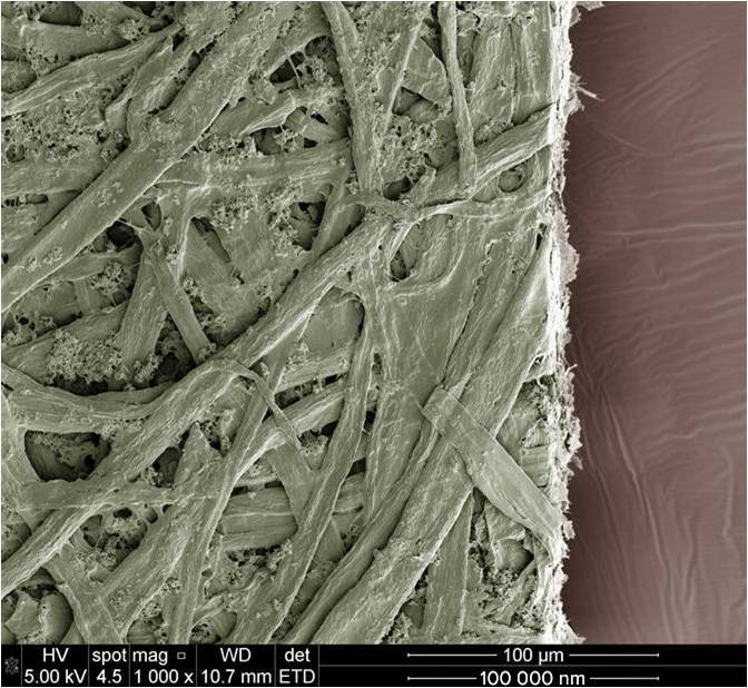
Here is an example from real life. In the picture is a sheet of A4 paper under an electron microscope. It can be seen that a sheet of paper actually consists of many intertwined wood fibers, but the eye does not distinguish them.
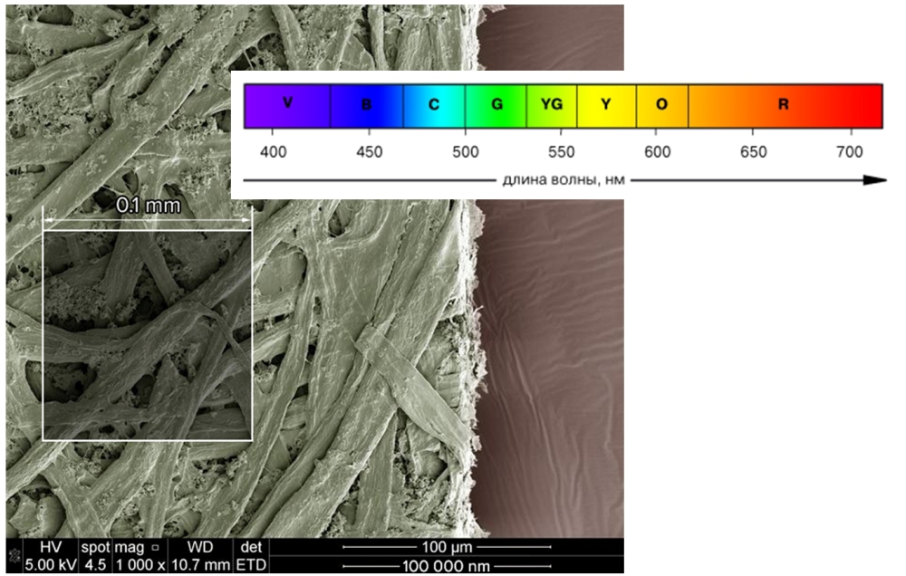
For scale, I derived wavelengths for a different spectrum of illumination in nanometers and selected a square with a side of 100,000 nanometers on the scan of the paper. Obviously, although we do not see these fibers, they affect the reflection of light.
Even offline filmmakers can calculate lighting with such a level of detail. This is a huge amount of computation.
So, surface microgeometry. Part of the light penetrates inside and is re-emitted after random reflections inside the material or is absorbed — it is converted into heat. Part of the incident light is reflected from the surface. There is a difference in how different materials reflect light. Two groups that behave differently are dielectrics and conductors (metals). Light does not penetrate inside the metal, and almost all of it is reflected from the surface. From dielectrics, light is mostly re-emitted, and a small amount of light is reflected — about 5%.
The theory is good, but we create a computer game and operate not with rays of light, but pixels on the screen. In addition, each pixel is a large number of photons of light. And all this light can be absorbed, reemitted or reflected. This is what we have to calculate when designing shaders.
BRDF
With the physics of the process in general, we decided to move on to the mathematical model. The main function that will allow us to determine what percentage of light was reflected, and which was reemitted or absorbed, is called the BRDF (Bidirectional Reflection Distribution Function) or in Russian DFOS (dual-beam reflectance function). The purpose of this function is to calculate the amount of energy emitted towards the observer for a given incoming radiation. In theory, this is a multidimensional function, which can depend on a large number of parameters 3D, 4D, 6D.
In practice, we will consider the function of the two parameters F (l, v) , where l is the direction from the surface point to the light source, and v is the direction of gaze.
BRDF for diffused light (Diffuse)
For the model of reradiated light, we make several assumptions:
- we can neglect the point of entry and exit of the beam, because this is a very small value in our case;
- we assume that all re-radiated rays are uniformly distributed inside the hemisphere.
The behavior of the photon inside the material is very complex, and for the current development of computer graphics this is a normal approximation, moreover, it adequately corresponds to real physical measurements.

We obtain the following function for the calculation of reradiated (scattered) light.
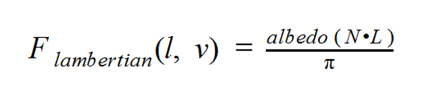
l is the direction to the light source, v is the direction of gaze, it is not used in any way in this simplified model, since all energy is reemitted uniformly over the hemisphere.
albedo (rgb) - determines how much energy the surface absorbs, and how much re-emits. So, for example, a surface with absolutely black albedo absorbs all energy (converts it into heat). In fact, this is known to all dot (n, l) graphical programmers, with the exception of the division by PI . The division by PI is necessary to comply with the law of energy conservation. Since the light is scattered over the hemisphere, then with n equal to l , we will reflect the incident light without changing the intensity in all directions along the hemisphere, which is physically impossible. But usually the intensity of the light source transmitted to the shader already takes into account the division by PI , therefore only the dot (n, l) remains in the shader.
We know that the dot product of vectors (dot) is the cosine between these vectors. The question arises: how does the angle of incidence of light affect the amount of reradiated light? The answer is simple: the projection area depends on the angle of incidence of the beam on the surface and is equal to the cosine of the angle of incidence. Accordingly, the sharper the angle of incidence, the less energy gets to the surface.
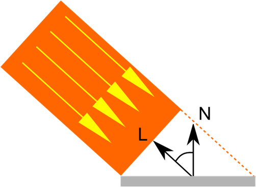
Light falls at a "blunt" angle.
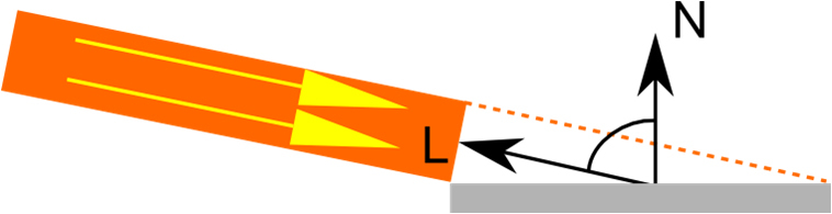
Light falls at an acute angle, the projection area has become larger
BRDF for reflected light (Specular)
Let us turn to the model of reflected light. Everyone knows that the angle of incidence is equal to the angle of reflection, but in the above picture there are many reflected rays. This is due to the irregularities of the surface. Due to these irregularities, each individual photon is reflected slightly in different directions. If the surface is sufficiently smooth, then most of the rays are reflected in one direction and we see a clear reflection of objects, such as in a mirror.
If the surface is more rough, then a much larger number of rays are reflected in different directions, and then we see a very dull reflection. For a highly irregular surface, the reflected light can be evenly distributed inside the hemisphere and look like a diffused light to an external observer.
Microfacet theory
Microfacet Theory was developed to simulate the effect of reflection of light from the surface, taking into account the surface microgeometry. This is a mathematical model that represents the surface as a set of microfaces oriented in different directions. At the same time, each of the microfaces is an ideal mirror and reflects light according to the same simple law: the angle of incidence equals the angle of reflection.
In order to calculate the illumination at a point, we need to calculate the sum of the contribution of the reflected light of each of the micrograins. Those. we need an integral. There are a lot of microfaces at a point, and we cannot simply integrate numerically. We will find the solution of the integral analytically (approximately). Here is what the function for calculating reflected light looks like in general.

This is a function of Cook-Torrens reflected light.
l - the direction of light
v - the direction of view of the observer
n - normal to the surface
h - vector between vectors l and v (half vector)
D (h) - the distribution function of micro faces
F (v, h) - Fresnel function
G (l, v, h) - the function of shading micro faces
All parameters of this function are quite simple and have a physical meaning. But what is the physical meaning of the half-vector? Half-vector is needed to filter out those micro-lands that contribute to the reflection of light for the observer. If the micrograin normal is half-vector, then this microface contributes to the illumination in the direction of view V.

Let us consider in more detail the members of our BRDF.
The distribution function of micro faces D (h)
As a distribution function of the light reflected from the microfaces, we use the degree of cosine, with rationing to observe the law of conservation of energy. First, we take the surface roughness coefficient, which lies in the range of 0..1, and calculate the degree of alpha from it, which lies in the range of 0.25 - 65536. Next, we take the scalar product of the N and H vectors and raise them to the degree of alpha. And so that the resulting result does not violate the energy conservation law, we apply the NDF normalization constant.
Without normalization, more energy will be reflected from the surface than it has come. Thus we set the volume in which the light is reflected and the energy is distributed in this volume. And this volume depends on how smooth or rough the surface is. Now consider the next BRDF member.
Fresnel function F (v, h)
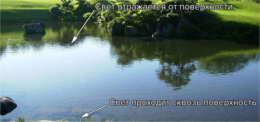
The intensity of light reflection depends on the angle of incidence. This behavior is described by Fresnel formulas. Fresnel formulas determine the amplitude and intensity of the reflected and refracted electromagnetic wave as it passes through the boundary of two media. This effect is very noticeable on water, if you look at water from an acute angle, water reflects most of the light and we see a reflection. If we look at the water from top to bottom, we practically do not see the reflections, but we see what is at the bottom.
So, for example, a graph of reflected light depending on the angle of incidence for various materials. Tabular data I took from the site http://refractiveindex.info/
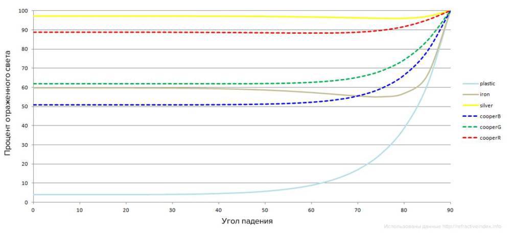
The graph shows that plastic scatters almost all the light, but does not reflect it, until the angle of incidence is 60-70 degrees. After that, the amount of reflected light increases dramatically. For most dielectrics, the graph will be similar.
Much more interesting is the situation with metals. Metals reflect a lot of light at any angle, but the amount of reflected light is different for different wavelengths. Dotted graphs show the reflection of light for copper. The wavelengths correspond to the red, green and blue colors. As you can see, red copper reflects much more, which is why metals paint reflected light in the color of their surface. And dielectrics reflect light without coloring it.
As a function to calculate the Fresnel, we use the Schlick approximation, since The original Fresnel equations are too heavy for real-time calculations.

As can be seen, the H and V vectors, which determine the angle of incidence, and F0 , with which the type of material is practically specified, participate in the Schlick function. The coefficient F0 can be calculated by knowing the Index of refraction (IOR) of the material we are modeling. In fact, it can be found in reference books on the Internet. Since we know that IOR of air 1, then, knowing the tabular IOR of the material, we calculate F0 by the formula

The physical meaning of F0 is the following: the percentage of light reflected at a right angle. So: the fresnel determines how much light will be absorbed, and how much is reflected depending on the angle of incidence.
F0 is used in the Schlick approximation and determines how much light is reflected at a right angle to the surface. The usual value of F0 for dielectrics is 2% - 5% , i.e. dielectrics reflect little and dissipate a lot.
Metals reflect almost all the light, while for different wavelengths this amount is different. Reflections on metals painted in the color of the surface. Now consider the next BRDF member.
The function of shading micro faces G (l, v, h)
In fact, not every microface, the normal of which corresponds to half-vector, contributes to the lighting. The ray reflected by the microface can not reach the observer.

The microgeometry of the surface can interfere with the reflected beam. It can be seen that part of the reflected rays will not reach the observer. Thus, not all micro-edges will participate in the reflection of light. We use the simplest function of visibility. In fact, we believe that all micro-edges reflect light. This is valid with our reflected light distribution function.
If we imagine that the microsurface is given by a height map (convex), then, if you look at the surface at a right angle and illuminate the surface, also at a right angle, but there are no such microfaces that do not participate in the lighting, because the surface is convex. At the same time, our function tends to zero at large angles, which also agrees with the representation of microgeometry in the form of a height map. Since the sharper the angle, the less microfaces reflect light.
This is our final function for calculating the reflected light:

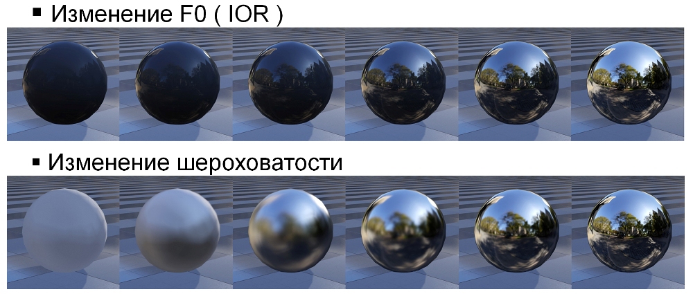
This corresponds to the normalized Blin-Phong model with a microsurface representation in the form of a height map. Here are some sample examples of how material parameters, roughness and IOR affect the appearance of the material.
Energy saving
I have repeatedly mentioned the conservation of energy. Saving energy means a simple thing: the sum of the reflected and scattered light must be less than or equal to one. It follows an important property for artists: the brightness and shape / area of the glare of the reflected light are related. Such a connection was not previously in the non-physical renderer, since there it is possible to violate the law of conservation of energy. For example - a series of images. The light source in all the pictures is the same; I will only change the surface roughness.
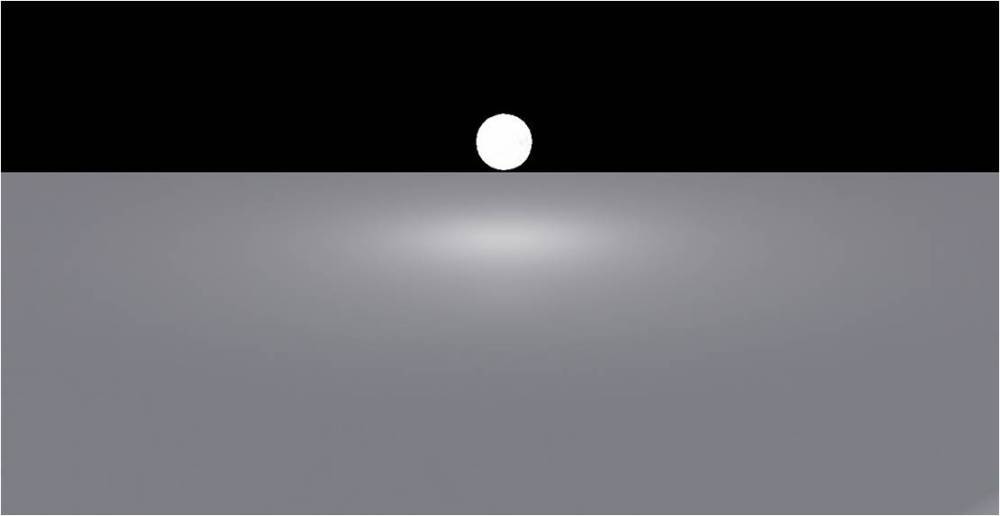


It can be seen that the smaller the glare area is distributed, the brighter it is.
Light source intensity
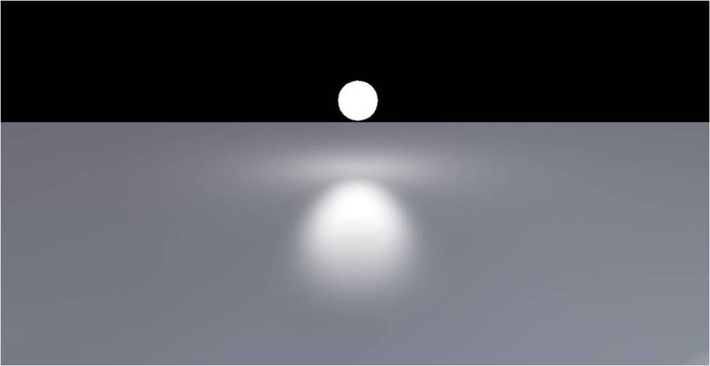
Our model is based on physics, and it is important for us to use honest attenuation of the energy of the light source. We know that the intensity of light is inversely proportional to the square of the distance to the light source. This behavior can be described by the following formula:
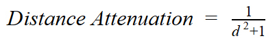
This feature is well suited to describe how energy fades, but has several drawbacks:
- we want to take into account the attenuation of energy not from a point in space, but from a volume, because in real life there are no sources of light that do not have their own size;
- The radiation intensity described by this function tends to zero, but never reaches it. We want the intensity to become zero at a certain distance. This is a simple optimization of computing resources, we do not need to calculate what does not affect the final result.
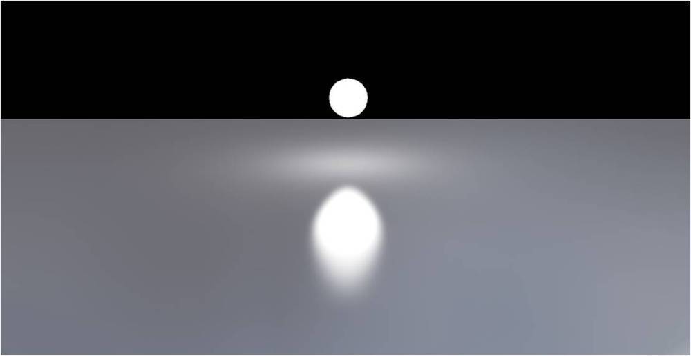
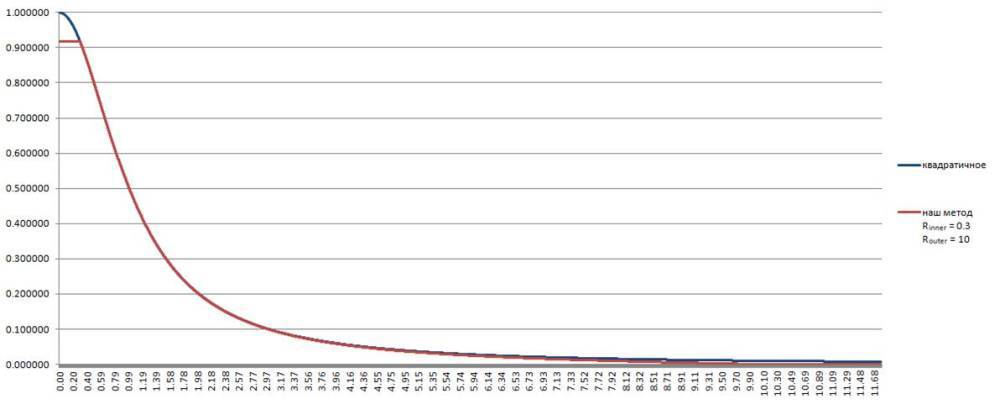
For the new light attenuation function, we will need two new parameters:
R inner is the size of the light source.
R outer is the distance at which the contribution of the source to the lighting is no longer important.
Our decay function:
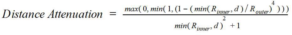
It has the following properties:
- Constant inside R inner .
- At a distance of R outer is equal to 0 .
- Corresponds to the square law of attenuation.
- Cheap enough to calculate in the shader.
// float GetAttenuation(float distance, float lightInnerR, float invLightOuterR) { float d = max(distance, lightInnerR); return saturate(1.0 - pow(d * invLightOuterR, 4.0)) / (d * d + 1.0); } Here is a comparison of two graphs. Quadratic attenuation and ours. It is seen that most of our function coincides with the quadratic one.
Material model
With physics and mathematics processes sorted out. Now we define what the artists influence. What kind of parameters do they customize? Our artists set the parameters of materials through textures. Here are the textures they create:
| for dielectrics | for metals | |
|---|---|---|
| Base color | sets the value of albedo | sets the vector part of F0 |
| Normal | normal to the surface (macro level) | normal to the surface (macro level) |
| Roughness (gloss) | surface roughness (micro level) | surface roughness (micro level) |
| Fresnel f0 | type of material (IOR) for dielectrics is almost always constant | for metals scalar part F0 |
| Metal | always 0 | always 1 |
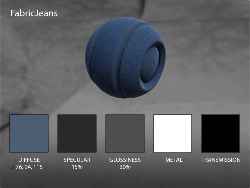
Here is an example of the surface properties of such a mechanical pegasus:
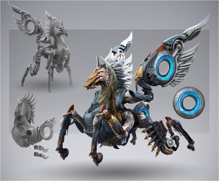
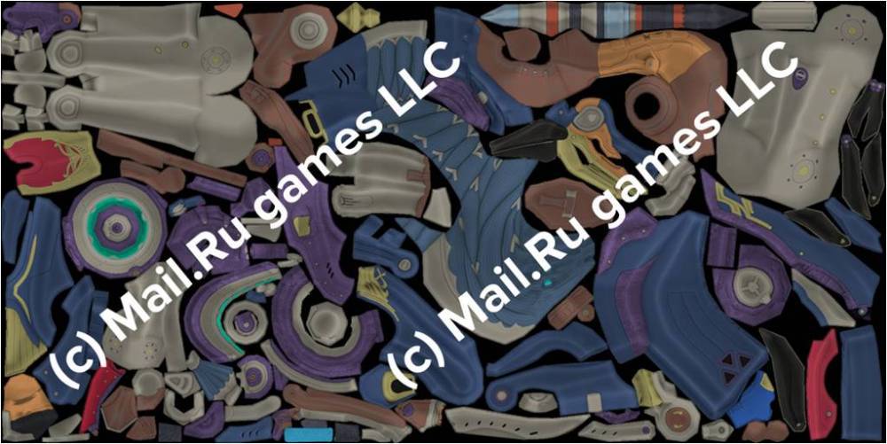
albedo

normal
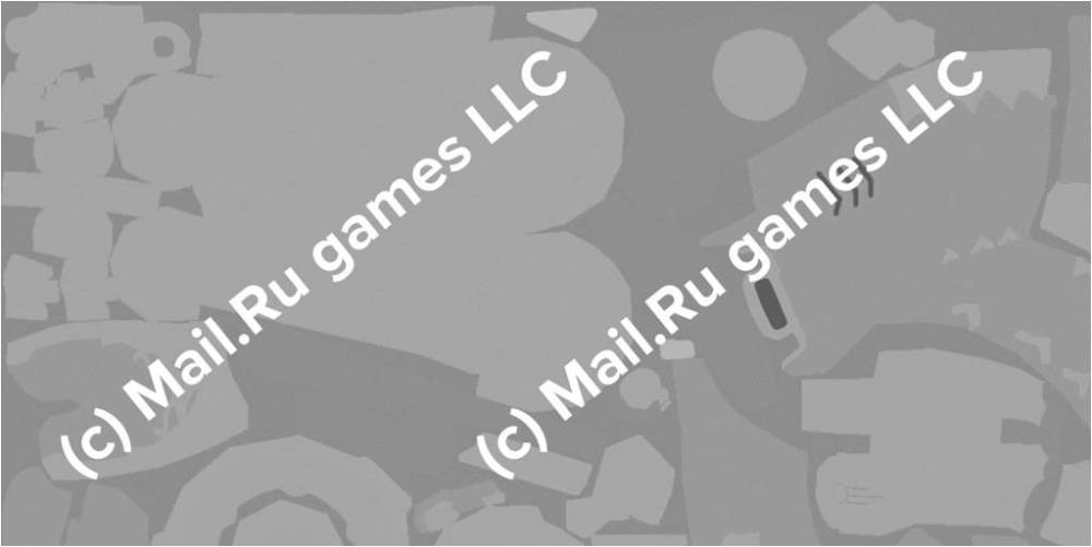
gloss
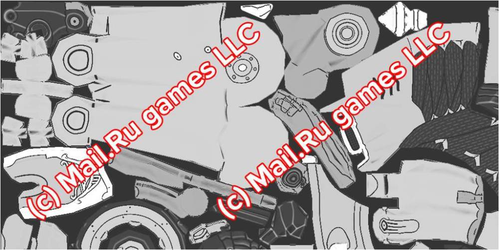
FO (IOR)
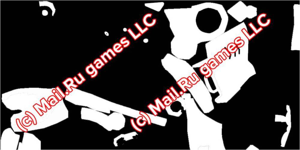
metal
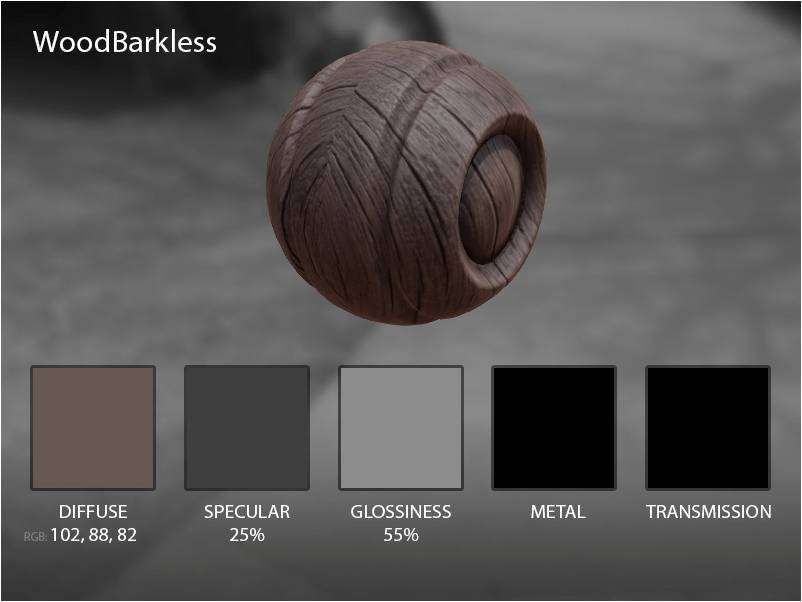
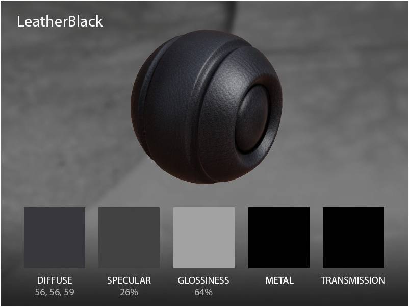
To simplify the work, our artists have compiled a fairly large library of materials. Here are some examples.


Deferred shading
When developing Skyforge we use a deferred shading model. This is a currently widely used method. The method is called deferred, because during the main rendering pass, only the buffer containing the parameters necessary for calculating the final shading occurs. Such a parameter buffer is called a G-Buffer, short for geometry buffer.
I will briefly describe the pros and cons of deferred shading:
Pros:
- Shaders geometry and lighting are separated.
- Easy to make a large number of light sources.
- Absence of combinatorial explosion in shaders.
Minuses:
- Bandwidth. You need a large memory bandwidth, because The surface parameter buffer is thick enough.
- Light sources with shadows are still expensive. Light sources without shadows have rather limited application.
- The complexity of embedding different BRDF. It's hard to make a different lighting model for different surfaces. For example, BRDF for hair or anisotropic metal.
- Transparency. Practically not supported, transparency needs to be drawn after the main picture is drawn and lit.
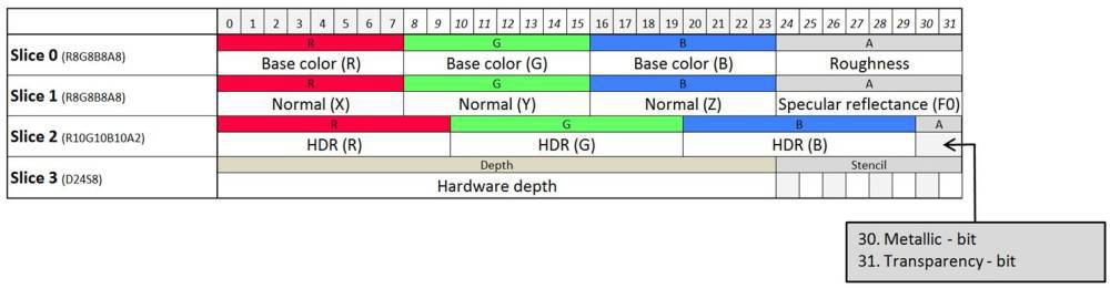
The main disadvantage of technology - need a large memory bandwidth. We try to pack the surface parameters necessary for lighting as much as possible. As a result, we have come to a format that fits into 128 bits per pixel - 96, if we ignore the depth information.
How we store surface properties (128 bits per pixel).
Skyforge g-buffer
Tips & Tricks
Position reconstruction
When using Deferred shading, we often encounter the need to reconstruct the position of a pixel in various spaces. For example, world space, view space, shadow space, etc. In our GBuffer, we store only the pixel depth using the hardware depth buffer. We need to be able to solve the problem: how to quickly obtain the position of a pixel in space, having only the hardware depth, which also has a hyperbolic distribution, and not a linear one. Our algorithm does this conversion in two steps.
Linear depth conversion
After we fill up the Gbuffer, we will convert the depth buffer with a hyperbolic distribution to a linear one. To do this, we use a full-screen step, “straightening” the depth. Conversion takes place using this shader:
// float ConvertHyperbolicDepthToLinear(float hyperbolicDepth) { return ((zNear / (zNear-zFar)) * zFar) / (hyperbolicDepth - (zFar / (zFar-zNear))); } We keep the linear depth in the R32F format and then at all stages of the render we use only the linear depth. The second stage is the reconstruction of the position using linear depth.
Position reconstruction using linear depth
To quickly reconstruct a position, we use the following property of similar triangles. The ratio of perimeters and lengths (either bisectors, or medians, or heights, or median perpendiculars) is equal to the similarity coefficient, i.e. in such triangles, the corresponding lines (heights, medians, bisectors, etc.) are proportional. Consider two triangles: a triangle (P1, P2, P3) and a triangle (P1, P4, P5).
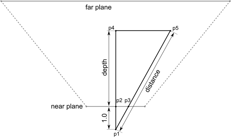
The triangle (P1, P2, P3) is similar to the triangle (P1, P4, P5).

Thus, we, knowing the distance (P1-P4) (our linear depth) and the hypotenuse (P1, P3), using the similarity of triangles, can calculate the distance of the pixel to the camera (P1, P5). And knowing the distance to the camera, the camera position and the direction of gaze, we can easily calculate the position in the camera space. The camera itself, in turn, can be set in any space: world space, view space, shadow space, etc., which gives us a reconstructed position in any space we need.
So, once again, the algorithm is in steps:
- Convert hyperbolic depth to linear.
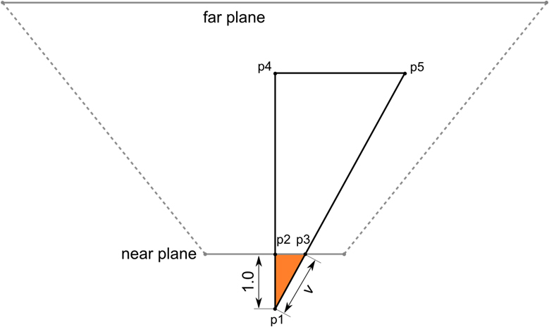
- In the vertex shader, calculate the triangle (P1, P2, P3).
- We transfer the segment (P1, P3) to the pixel shader, via the interpolator.
- We get the interpolated vector RayDir (P1, P3).
- Read the linear depth at this point.
- Position = CameraPosition + RayDir * LinearDepth.
The algorithm is very fast: one interpolator, one ALU MAD instruction and one depth reading. You can reconstruct the position in any convenient homogeneous space. HLSL code for reconstruction at the end of the article.
Reversed Depth Buffer
When developing Skyforge, we were faced with the task: to be able to draw locations with a very large visibility range, about 40 km. Here are some pictures illustrating the drawing distance.


In order to avoid Z-fighting with large Far Plane values, we use the technique of reversed depth buffer. The meaning of this technique is very simple: when calculating the projection matrix, you need to swap Far Plane and Near Plane and invert the depth comparison function by more or equal (D3DCMP_GREATEREQUAL). This trick works only if you swap FarPlane and NearPlane in the projection matrix. The trick does not work if you change the viewport parameters or expand the depth in the shader.
Now I will explain why this is happening, and where we win in the accuracy of calculations. To understand where accuracy is lost, let's figure out how the projection matrix works.

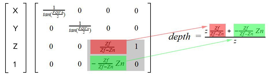
So, the standard projection matrix. We are interested in that part of the matrix, which is highlighted in gray. Z and W position components. How is the depth calculated?
// float4 postProjectivePosition = mul( float4(pos, 1.0), mtxProjection ); // float depth = postProjectivePosition.z / postProjectivePosition.w; After multiplying the position on the projection matrix, we obtain the position in the post-projective space. After the perspective division by W, we get the position in the clip space, this space is given by the unit cube. Thus, the following transformation is obtained.
For example, consider Znear and Zfar, the distance between which is very large, about 50 km.
Znear = 0.5
Zfar = 50000.0
We obtain the following two projection matrices:
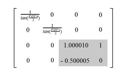
Standard Projection Matrix

Extended Projection Matrix
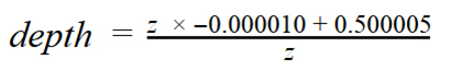
The depth after multiplying by the standard projection matrix will be equal to the following:
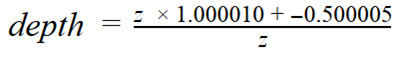
Accordingly, after multiplying by the unfolded projection matrix:
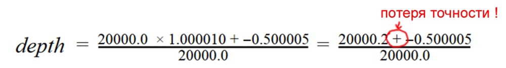
As we can see, in the case of the standard projection matrix, when calculating the depth, the addition of numbers of very different order will occur - tens of thousands and 0.5. To add numbers of different order, the FPU must first bring their exponents to a single value (greater exponential), then add and normalize the addition obtained by the mantis. In fact, at large z values, this simply adds white noise to the low bits of the mantis. In the case of using the unfolded projection matrix, this behavior occurs only near the camera, where, due to the hyperbolic distribution of depth, there is already excessive accuracy. Here is an example of what happens when the value of z = 20 km:
And for the unfolded projection matrix:

Total:
- The standard 24-bit D24 depth buffer easily covers a range of 50 km without Z-fighting.
- Reverse depth is suitable for any engine, I would recommend to use it in all projects.
- It is best to build support from the beginning of development, because There are many places that may have to be redone: extracting the frustum planes from the projection matrix, bias from the shadows, etc.
- If a float depth buffer is available on the target platform, then it is best to use it. This will further increase the accuracy, because values will be stored with greater accuracy.
That's all, thank you for your attention!
Literature
Naty Hoffman. Crafting Physically Motivated Shading Models for Game Development
Yoshiharu Gotanda. Practical implementation at tri-Ace
Emil Persson. Creating vast game worlds
Nickolay Kasyan, Nicolas Schulz, Tiago Sousa. Secrets of CryENGINE 3 Graphics Technology
Eric Heitz. Understanding the Masking-Shadowing Function
Brian Karis. Real Shading in Unreal Engine 4
HLSL reconstruction code (vertex shader)
// float tanHalfVerticalFov; // invProjection.11; float tanHalfHorizontalFov; // invProjection.00; // float3 camBasisUp; float3 camBasisSide; float3 camBasisFront; // postProjectiveSpacePosition homogeneous projection space float3 CreateRay(float4 postProjectiveSpacePosition) { float3 leftRight = camBasisSide * -postProjectiveSpacePosition.x * tanHalfHorizontalFov; float3 upDown = camBasisUp * postProjectiveSpacePosition.y * tanHalfVerticalFov; float3 forward = camBasisFront; return (forward + leftRight + upDown); } void VertexShader(float4 inPos, out float4 outPos : POSITION, out float3 rayDir : TEXCOORD0) { outPos = inPos; rayDir = CreateRay(inPos); } HLSL reconstruction code (pixel shader)
// float3 camPosition; float4 PixelShader(float3 rayDir : TEXCOORD0) : COLOR0 { ... float linearDepth = tex2D(linearDepthSampler, uv).r; float3 position = camPosition + rayDir * linearDepth; ... } // float ConvertHyperbolicDepthToLinear(float hyperbolicDepth) { return ((zNear / (zNear-zFar)) * zFar) / (hyperbolicDepth - (zFar / (zFar-zNear))); } Slides original report
www.slideshare.net/makeevsergey/skyforge-rendering-techkri14finalv21
Source: https://habr.com/ru/post/248873/
All Articles