A brief course of computer graphics: we write a simplified OpenGL do it yourself, article 4b of 6
Course content
- Article 1: Bresenham algorithm
- Article 2: rasterization of the triangle + clipping of the rear faces
- Article 3: Removing invisible surfaces: z-buffer
- Article 4: Required Geometry: Matrix Festival
- 4a: Construction of perspective distortion
- 4b: we move the camera and what follows from this
- 4c: a new rasterizer and perspective distortion correction
- Article 5: We write shaders for our library
- Article 6: A little more than just a shader: shadow rendering
Code enhancement
The official translation (with a bit of polishing) is available here.
')
Today we are finishing with an educational program on geometry, next time there will be fun with shaders!
In order not to be completely boring, here is the Guro Tinting:
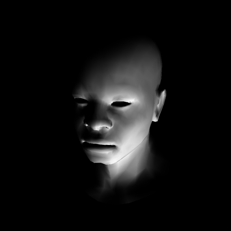
I removed the texture to make it more visible. Guro 's tinting is very simple: the kind uncle modeler gave us normal vectors to each vertex of the object, they are stored in the lines vn xyz of the .obj file. We count the light intensity for each vertex of the triangle and just interpolate the intensity inside. Exactly as we did for the depth z or for the texture coordinates uv!
By the way, if the uncle-modeler were not so kind, then we could count the normals to the vertex as the average of the normals of the faces adjacent to this vertex.
The current code that generated this image is here .
Likbez: a change of basis in three-dimensional space
In Euclidean space, the coordinate system (frame) is defined by the reference point and the basis of space. What does it mean that in the frame (O, i, j, k) point P has coordinates (x, y, z)? This means that the vector OP is defined as follows:

Now imagine that we have a second rapper (O ', i', j ', k'). How do we convert the coordinates of a point given in one frame to another frame? To begin with, we note that, since (i, j, k) and (i ', j', k ') are bases, there exists a non-degenerate matrix M, such that:

Let's draw an illustration to make it clearer:

Let us write down the representation of the vector OP:

Substitute in the second part of the expression replacement basis:

And this will give us a formula for changing coordinates for two bases.

Writing your gluLookAt
OpenGL and, as a result, our small renderer can only draw scenes with a camera located on the z axis . If we need to move the camera, do not worry, we just move the whole scene, leaving the camera still.
Let's set the task as follows: we want to make the camera at the point e (eye), look at the point c (center) and the specified vector u (up) in our final image be vertical.
Here is an illustration:

It simply means, we render the reper (c, x'y'z '). But the model is specified in the frame (O, xyz), which means that we need to calculate the frame x'y'z 'and the corresponding transition matrix. Here is the code that returns the matrix we need:
update: carefully, in the repository the wrong code is correct here
void lookat(Vec3f eye, Vec3f center, Vec3f up) { Vec3f z = (eye-center).normalize(); Vec3f x = cross(up,z).normalize(); Vec3f y = cross(z,x).normalize(); Matrix Minv = Matrix::identity(); Matrix Tr = Matrix::identity(); for (int i=0; i<3; i++) { Minv[0][i] = x[i]; Minv[1][i] = y[i]; Minv[2][i] = z[i]; Tr[i][3] = -center[i]; } ModelView = Minv*Tr; } Let's start with the fact that z 'is just a vector ce (let's not forget to normalize it, it's easier to work). How to calculate x '? Just a vector product between u and z ' . Then we assume y ', which will be orthogonal to the already calculated x' and z '(recall that, by the condition of the problem, the vector ce and u are not necessarily orthogonal). The most recent chord is doing a parallel translation in c , and our coordinate translation matrix is ready. It is enough to take any point with coordinates (x, y, z, 1) in the old basis, multiply it by this matrix, and we get the coordinates in the new basis! In OpenGL, this matrix is called the view matrix.
Viewport
If you remember, I had such constructions in my code:
screen_coords [j] = Vec2i ((v.x + 1.) * width / 2., (v.y + 1.) * height / 2.);
What does this mean? I have a point Vec2f v, which belongs to the square [-1,1] * [- 1,1]. I want to draw it in the picture size (width, height). The vector (v.x + 1) varies from 0 to 2, (v.x + 1.) / 2. ranging from zero to one, well, a (v.x + 1.) * width / 2. sweeps the whole picture, and that's what I need.
But we are moving to the matrix representation of affine mappings, so let's consider the following code:
 Matrix viewport (int x, int y, int w, int h) {
     Matrix m = Matrix :: identity (4);
     m [0] [3] = x + w / 2.f;
     m [1] [3] = y + h / 2.f;
     m [2] [3] = depth / 2.f;

     m [0] [0] = w / 2.f;
     m [1] [1] = h / 2.f;
     m [2] [2] = depth / 2.f;
     return m;
 }
He builds just such a matrix:

This means that the world coordinates cube [-1,1] * [- 1.1] * [- 1.1] is mapped to the screen coordinates cube (yes, cube, because we have a z-buffer!) [ x, x + w] * [y, y + h] * [0, d], where d is the resolution of the z-buffer (I have 255, since I store it directly in a black and white picture).
In the OpenGL world, this matrix is called the viewport matrix.
Transformation chain
So, we summarize. Models (for example, characters) are made in their local coordinate system (object coordinates). They are inserted into the scene, which is expressed in world coordinates (world coordinates). The transition from one to another is carried out by the matrix Model. Further, we want to express this matter in the frame of the camera (eye coordinates), the matrix of transition from world to camera is called View. Then, we perform perspective distortion using the Projection matrix (see article 4a), it translates the scene into so-called clip coordinates. Well, and then we display this whole thing on the screen, the transition matrix to the screen coordinates is Viewport.
That is, if we read the point v from the file, then in order to show it on the screen, we do the multiplication
Viewport * Projection * View * Model * v.
If you look at the code on the githaba , we will see these lines:
 Vec3f v = model-> vert (face [j]);
 screen_coords [j] = Vec3f (ViewPort * Projection * ModelView * Matrix (v));
Since I draw only one object, I only have a single Model matrix, I have combined it with the View matrix.
Transform normal vectors
The following fact is widely known:
If we have a given model and have already calculated (or, for example, given by hands) normal vectors to this model, and this model undergoes an (affine) transformation of M, then normal vectors undergo a transformation inverse to the transposed M.
I'm sorry, what?!
This moment remains magical for many, but in fact, there is nothing magic here. Consider a triangle and a vector a , which is normal to its inclined face. If we simply stretch our space two times vertically, then the transformed vector a will no longer be normal to the transformed face.
In order to remove the entire magic raid, you need to understand one simple thing: we need not just to transform normal vectors, we need to calculate normal vectors to the transformed model.
So, we have a normal vector a = (A, B, C). We know that the plane passing through the origin, and having the normal vector a (in our illustration it is an inclined edge of the left triangle), is given by the equation Ax + By + Cz = 0. Let's write this equation in a matrix form, and immediately in homogeneous coordinates:

I recall that (A, B, C) is a vector, so it gets a zero in the last component when immersed in four-dimensional space, and (x, y, z) is a point, so we assign 1 to it.
Let's add the unit matrix (M multiplied by its inverse) in the middle of this record:

The expression in the right brackets is converted points. In the left - a normal vector! Since we write vectors (and points) in a column in a standard convention in linear mapping (I hope we will not ignite holivar about contra- and contravariant vectors), the previous expression can be written as follows:

What exactly leads us to the above fact that the normal to the transformed object is obtained by transforming the original normal, inverse to the transposed M.
Note that if M is a composition of parallel translations, rotations and uniform stretchings, then the transposed M equals the inverse of M, and they cancel each other. But since our transformation matrices will include perspective distortion, this will not help us much.
We do not use normal transformation in the current code, but in the next article about shaders this will be very important.
Happy programming!
Source: https://habr.com/ru/post/248723/
All Articles