STM32L0538-DISCO: short description + interesting application
For quite some time now, a new motherboard from the STMicroelectronics discovery series has appeared on the market. I think it will be interesting for the habrasoobshchestvo to get to know her better. Under the cut, you will have a brief overview of the new de-payment and an interesting example of its use.
The board is intended to demonstrate the capabilities of the STM32L053C8, a representative of the ultra low-power microcontroller series. In addition to it, there is another chip from the ST on the board (STM32L152CCT6), which measures the current consumed by the main MC in various modes. Traditionally, the ST-Link programmer / debugger (version 2.1) is implemented on the board, which allows you to flash and debug both the target MK and external chips via the SWD interface. ST-Link 2.1 also implements a USB-COM converter, and also appears in the system as a removable disk, allowing the microcontroller to be flashed by simply copying a binary file.
Useless remark
Since ST-Link is also implemented on a chip from ST (STM32F103CBT6), it turns out that by buying one debug board, you get as many as 3 different MCs on it!
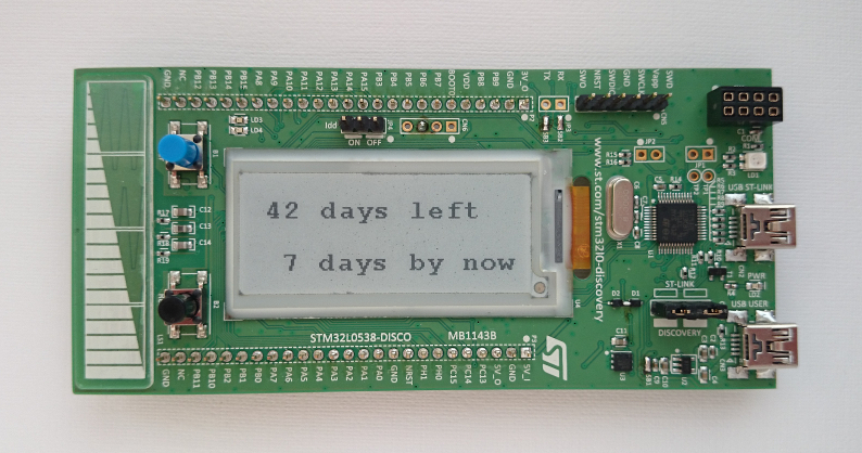
The main feature of the board is the display, made by electronic ink technology. The display is not large (2.04 inches, 172x72) and it is far from the fellows installed in e-books, but it is quite suitable for displaying various information.
')
The board comes with a demo firmware, which works in two modes (however, only the first is sensible of them): measurement and display of current consumed by the STM32L053C8 on the e-ink screen or in USB mouse mode. The choice of modes is carried out by a touch slider.
Board application concept
When I received a fee and saw the ST logo on a de-energized screen, I immediately wanted to make an autonomous, practically energy-consuming device that would display some rarely changing information. You can forget about him at all, but it will still show something after months or even years. For example, how many days are left before any event. This is how the concept of the device was born: an electronic paper countdown of the countdown days, which will always remind you of the inexorable approach of the deadline, the new year, the birthday (underline the appropriate).
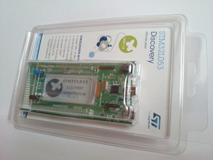
No sooner said than done! After some time, the debug board turned into a device. To power the battery is used small capacity. You can use any one with a voltage of 3 V; I have this CR2032 “tablet” in a holder. The microcontroller is in sleep mode with the real-time clock (RTC) module turned on. When the next day comes, the RTC wakes up the controller, which updates the countdown counter of days on the screen. Since the screen consumes energy only in the process of redrawing, the battery feeds the clock in the controller all the main time and only occasionally the energy is spent on updating the counter. USB is used for configuration (more precisely, UART via USB-COM converter provided by the debugger on the board). The board, together with the battery, perfectly fits in its own plastic packaging. In the process of implementation, one more function was added - an incremental day counter, which is reset by pressing the User button. This can be useful for motivation, for example: “I do not smoke 38 days”, “I did not miss training for 15 days”, etc. Well, or something like: "56 days without incidents".
Implementation
Now that needs to be done to make it all work. Since on the board in addition to the STM32L053C8 and the display, there are two other MKs, you need to modify it in order not to waste battery energy.
Finalization in pictures
1. Solder the jumper SB13 and resistors R44, R50:

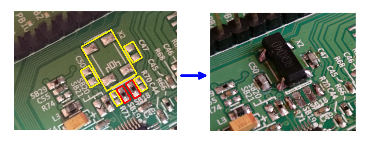
2. We mount on the board quartz X2 (32.768 kHz), capacitors C47 and C50 (~ 10 pF), resistors R70 and R71 are closed with solder drops. It is also desirable to unsolder the SB18, SB19 jumper resistors (they can be soldered in place of the R70 and R71).
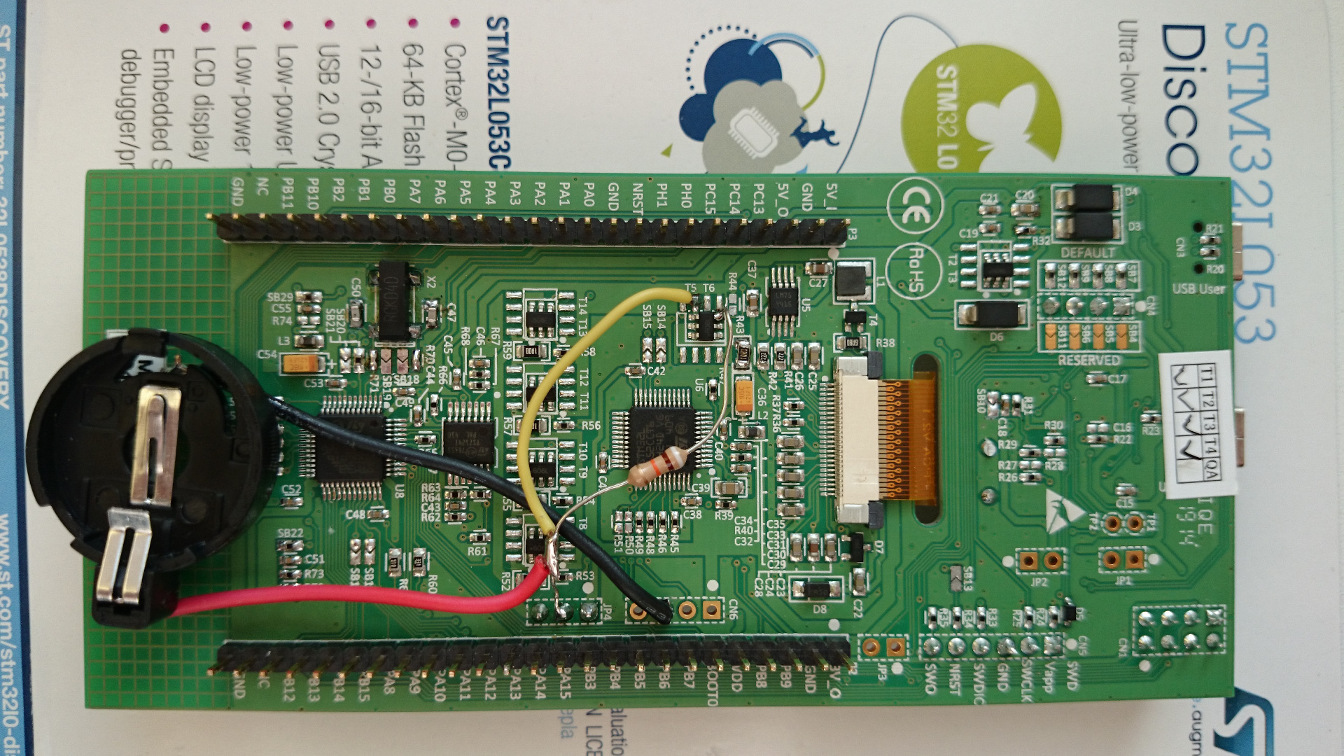
3. Cut the track on the board near the T6 transistor, add a 100 kΩ resistor, a holder for a CR2032 battery:

It should look like this:
4. Close the jumpers SB2, SB3:
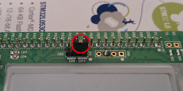
5. Remove jumper from JP4 connector:
That's all!
2. We mount on the board quartz X2 (32.768 kHz), capacitors C47 and C50 (~ 10 pF), resistors R70 and R71 are closed with solder drops. It is also desirable to unsolder the SB18, SB19 jumper resistors (they can be soldered in place of the R70 and R71).
3. Cut the track on the board near the T6 transistor, add a 100 kΩ resistor, a holder for a CR2032 battery:
It should look like this:
4. Close the jumpers SB2, SB3:
5. Remove jumper from JP4 connector:
That's all!
Learn more about hardware changes (careful, many letters)
It is necessary to power only the STM32L053C8 and the display. Regular way to do this is not provided. There is a 5V_in contact, but ST-Link will also be powered from it along with a current-measuring MK. All this is fed through stabilizers, on which there will also be losses. We need to add a battery, at the same time it is possible to preserve the functionality of the board as much as possible (of course you can drop all the excess, but this is not our way).
The SB13 jumper needs to be evaporated to disable the T_NRST reset signal that ST-Link generates. You can do without this signal, the STM32L053C8 will be flashed without it (unless you have to press the reset button if it is in sleep mode).
The R50 resistor needs to be removed, since through it the current-measuring MK is parasitically powered by the VDD bus, to which we will apply the battery voltage.
A clock source is required for RTC operation. External "clock" quartz at 32.768 kHz, is absent on the board (but space is provided for it) and to avoid unnecessary rework, I first tried to use the oscillator built into the MK RC. The accuracy of this solution turned out to be absolutely unacceptable (the clock ran away for half an hour per day), so quartz X2, two capacitors C47 and C50 (~ 10 pF 0603) need to be soldered for and connected to the MC. It is supposed to connect the quartz by soldering two resistors R70 and R71, but I managed to get by with just drops of solder. It is also desirable to remove the SB18 and SB19 jumpers (they can be soldered in place of R70 and R71) so that the quartz signal tracks do not go to the board connectors.
I still need to cut one track (I don’t like to cut tracks, but here it’s the lesser of two evils). The fact is that STM32L053C8 controls the power of the display through the T6 transistor and this possibility needs to be preserved, since if you power the display directly from the battery and do not turn it off for periods of inactivity, there will be excess consumption. The T6 transistor supplies power to the display from the 3V3 bus, which is connected to the current-measuring MK and its harness. Since we do not want to spend energy on it, we will not power the 3V3 bus at all and connect plus batteries to the VDD bus. This means that the VDD bus must be fed to the source of the T6 transistor, and 3V3 should be removed. That is why it is necessary to cut off this line from it and apply battery voltage to this point.
Still have to drop out resistor R44. It could have been left, but then it would have to be engaged in figured cutting of copper, so it would be easier to remove it and replace it with a discharge face value of 100 kΩ. This resistor pulls the gate of the transistor to power to prevent accidental opening.
The battery is soldered with a plus to the VDD bus, and with a minus it needs to be connected to GND. The VDD bus is actually the power supply pin of the STM32L053C8, so the battery voltage will go directly to it, without voltage stabilizers and any protection against polarity reversal. It is necessary to observe the polarity and supply no more than 3.3 volts (maximum allowable 3.6).
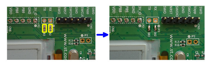
And the last revision: the closure of the jumpers SB2, SB3. To set the time and date, the serial port of the MC (USART1) connected to the UART-USB converter, implemented on ST-LINK v2.1, is used. This connection is made by closing the jumpers SB2, SB3.
The SB13 jumper needs to be evaporated to disable the T_NRST reset signal that ST-Link generates. You can do without this signal, the STM32L053C8 will be flashed without it (unless you have to press the reset button if it is in sleep mode).
The R50 resistor needs to be removed, since through it the current-measuring MK is parasitically powered by the VDD bus, to which we will apply the battery voltage.
A clock source is required for RTC operation. External "clock" quartz at 32.768 kHz, is absent on the board (but space is provided for it) and to avoid unnecessary rework, I first tried to use the oscillator built into the MK RC. The accuracy of this solution turned out to be absolutely unacceptable (the clock ran away for half an hour per day), so quartz X2, two capacitors C47 and C50 (~ 10 pF 0603) need to be soldered for and connected to the MC. It is supposed to connect the quartz by soldering two resistors R70 and R71, but I managed to get by with just drops of solder. It is also desirable to remove the SB18 and SB19 jumpers (they can be soldered in place of R70 and R71) so that the quartz signal tracks do not go to the board connectors.
I still need to cut one track (I don’t like to cut tracks, but here it’s the lesser of two evils). The fact is that STM32L053C8 controls the power of the display through the T6 transistor and this possibility needs to be preserved, since if you power the display directly from the battery and do not turn it off for periods of inactivity, there will be excess consumption. The T6 transistor supplies power to the display from the 3V3 bus, which is connected to the current-measuring MK and its harness. Since we do not want to spend energy on it, we will not power the 3V3 bus at all and connect plus batteries to the VDD bus. This means that the VDD bus must be fed to the source of the T6 transistor, and 3V3 should be removed. That is why it is necessary to cut off this line from it and apply battery voltage to this point.
Still have to drop out resistor R44. It could have been left, but then it would have to be engaged in figured cutting of copper, so it would be easier to remove it and replace it with a discharge face value of 100 kΩ. This resistor pulls the gate of the transistor to power to prevent accidental opening.
The battery is soldered with a plus to the VDD bus, and with a minus it needs to be connected to GND. The VDD bus is actually the power supply pin of the STM32L053C8, so the battery voltage will go directly to it, without voltage stabilizers and any protection against polarity reversal. It is necessary to observe the polarity and supply no more than 3.3 volts (maximum allowable 3.6).
And the last revision: the closure of the jumpers SB2, SB3. To set the time and date, the serial port of the MC (USART1) connected to the UART-USB converter, implemented on ST-LINK v2.1, is used. This connection is made by closing the jumpers SB2, SB3.
After the above manipulations, the current consumption of the board in the rest period (MK in Standby with RTC mode) became equal to 0.7 μA, which is extremely small and the batteries should be enough for a long time (years). At the same time, it is possible to use the built-in ST-Link for firmware STM32L053C8. You can flash without disconnecting the battery, the main thing is that JP4 jumper is missing. If you want to work with the board without a battery, then you need to disconnect the battery, return to place JP4 jumper (OFF position) so that the STM32L053C8 is powered from the board. But if a battery is connected and a JP4 jumper is worn, the board cannot be connected to USB, because then the voltage from the board will go to the battery!
Program
The program is written in EmBlocks 2.30 (compiler ARM-GCC) and is based on examples of working with peripherals from the STM32Cube_FW_L0_V1.1.0 package. In general, I wanted to use CoIDE, but he still does not support this MC.
A few words about the algorithm of the program and how to use the device. After reset, it is checked whether the date and time are set. If not, the screen prompts you to set the clock using the terminal:
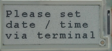
To do this, you need to connect the board to the computer using the USB connector (central). In the terminal, set the speed / parity: 9600, 8n1, open the connection, and press the Reset button on the board. A prompt should appear in the terminal to set the date and time. You also need to set the number of days for the countdown. After successful configuration, 2 counters are displayed on the screen: increase and decrease the number of days. Then the microcontroller goes into Standby mode (the most energy efficient). It can be awakened by the arrival of a new day (at midnight), by pressing the Reset button or the User button. When a new day comes, both counters are displayed on the screen. To reset the increasing counter, press the User button (it is strictly forbidden to do this at midnight!). To view the current time and date, press the reset button. If you need to change the time and date (for example, to adjust the clock) or set a new countdown counter, this can be done if after pressing the Reset button, within 10 seconds, to establish a connection over the terminal (press Enter). The screen will then:

Sources and ready hex file are available on github .
Possible improvements:
- Cyrillic support, so that you can describe an event on the screen itself, for example: “There are 365 days left until the new year”;
- abandon configuration via terminal in favor of removable disk emulation. Then, to configure, you will need to edit a text file in which to set the date / time, the new value of the counter and the displayed phrase.
Source: https://habr.com/ru/post/248691/
All Articles