A brief course of computer graphics: we write a simplified OpenGL do it yourself, article 4a of 6
Course content
- Article 1: Bresenham algorithm
- Article 2: rasterization of the triangle + clipping of the rear faces
- Article 3: Removing invisible surfaces: z-buffer
- Article 4: Required Geometry: Matrix Festival
- 4a: Construction of perspective distortion
- 4b: we move the camera and what follows from this
- 4c: a new rasterizer and perspective distortion correction
- Article 5: We write shaders for our library
- Article 6: A little more than just a shader: shadow rendering
Code enhancement
The official translation (with a bit of polishing) is available here.
Building perspective distortion
The fourth article will be divided into two, the first part talks about building perspective distortion, the second about how to move the camera and what follows from this. The task for today is to learn how to generate the following images:
')
Geometry on the plane
Linear plane transform
A linear mapping on the plane is given by the corresponding matrix. If we take the point (x, y), then its transformation is written as follows:

The simplest (non-degenerate) transformation is given by the identity matrix; it simply leaves each point in place.

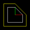
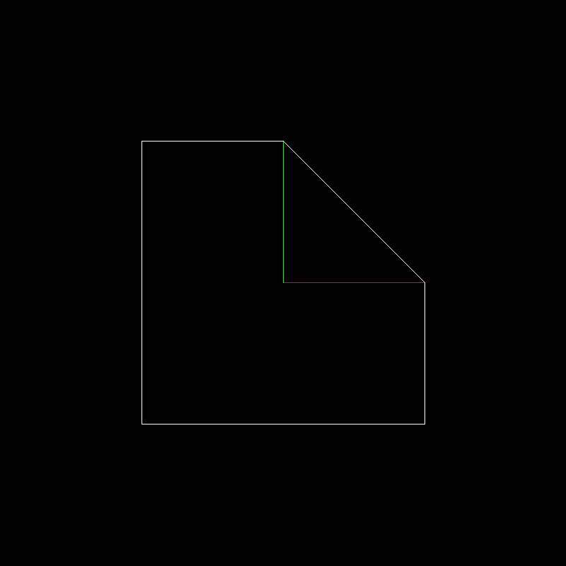
The coefficients on the diagonal of the matrix set the stretching / compression of the plane. Let's illustrate with a picture: for example, if we write the following transformation:

That white object (a square with a cut corner) is converted to yellow. Red and green segments give unit vectors along the x and y axis, respectively.
All pictures for this article are generated here by this code.
Why even use the matrix? Because it is convenient. To begin with, in the matrix form, the transformation of the entire object can be written like this:

Here the transformation is the same as in the previous example, but the matrix in two rows and five columns is nothing more than an array of coordinates of our cube with a cut corner. We simply took the entire array, multiplied by the transformation, and obtained the already transformed object. Handsomely? Okay, I agree, far-fetched.
The real reason is that, extremely regularly, we want the object to undergo several transformations in a row. Imagine that you are writing a type conversion function in your code.
 vec2 foo (vec2 p) return vec2 (ax + by, cx + dy);
 vec2 bar (vec2 p) return vec2 (ex + fy, gx + hy);
 [..]
 for (each p in object) {
     p = foo (bar (p));
 }
This code makes two linear transformations for each vertex of the object, and they are calculated in millions. And often we want transformations with a good ten. Expensive. And with the matrix approach, we multiply all the transformation matrices and multiply by our object once. In multiplication, we can put brackets where we want, right?
We continue the conversation, we know that the diagonal elements give us the scaling along the axes. What are the two other matrix coefficients responsible for? Let's look at this conversion:

The corresponding picture:
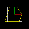
Nothing but a simple shift along the x axis. The second anti-diagonal element will give a shift along the y axis. Thus, there are only two basic linear transformations on the plane: stretching along the axes and shifting along the axis. Wait, they will tell me, but what about, for example, rotation around the origin?
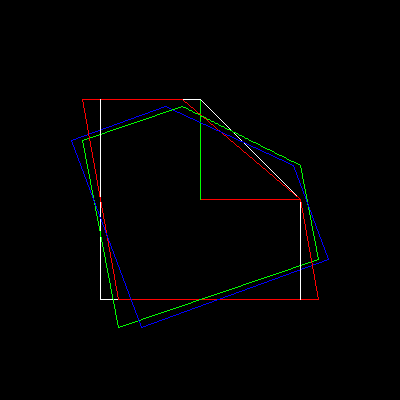
It turns out that the rotation can be represented as a composition of three shifts, here the white object is converted first to red, then to green, then to blue:
But let's not go to extremes, the counterclockwise rotation matrix around the origin can be written directly (remember about the placement of brackets?):

We can, of course, multiply in any order, just let's not forget that for matrices multiplication is noncommutative:

What is normal, move and then rotate (red object) is not the same as first rotate, and then move (green object):

Affine transformations on the plane
That is, any linear transformation on the plane is a composition of stretchings and shifts. Which means that whatever the matrix of our transformation, the origin always goes to the origin. Thus, linear transformations are fine, but if we cannot imagine an elementary parallel translation, then our life will be sad. Or can we? But what if you add it separately and record the affine transformation as a composition of the linear part and parallel translation? Like this:

This is, of course, a wonderful record, but just let us see what the composition of two such transformations looks like (I remind you that in real life we need to be able to accumulate dozens of transformations):

It starts to look extremely unpleasant already for a single composition. Try converting this expression to apply only one kind of linear transformation + parallel translation to our object. Personally, I really do not want to do this.
Homogeneous coordinates
And what to do? Cast a spell! Imagine now that I’ll add one line and one column to our transformation matrix and add a third coordinate, which is equal to one in the vector that we transform:

When multiplying this 3x3 matrix and our vector supplemented with a unit, we again obtained a vector with a unit in the third component, and the other two have exactly the form we wanted! Witch.
In fact, the idea is very simple: parallel translation is not a linear operation in a two-dimensional space.
Therefore, we immerse our two-dimensional space in three-dimensional (adding one to the third component). This means that our two-dimensional space is the plane z = 1 inside three-dimensional. Then we do a linear transformation in three-dimensional space and project the entire three-dimensional space back onto our physical plane. The parallel transfer from this did not become linear, but the pipeline is still simple.
How exactly do we project the three-dimensional space back into our plane? Very simple:

Wait a second, but you can't divide by zero!
Who told you? Joke. Let's understand what is happening again.
- We immerse our 2d space in 3d, making it the plane z = 1
- We do what we want in 3d
- For each point that we want to project back to 2d, draw a line between the origin and this point and look for its intersection with the physical plane z = 1.
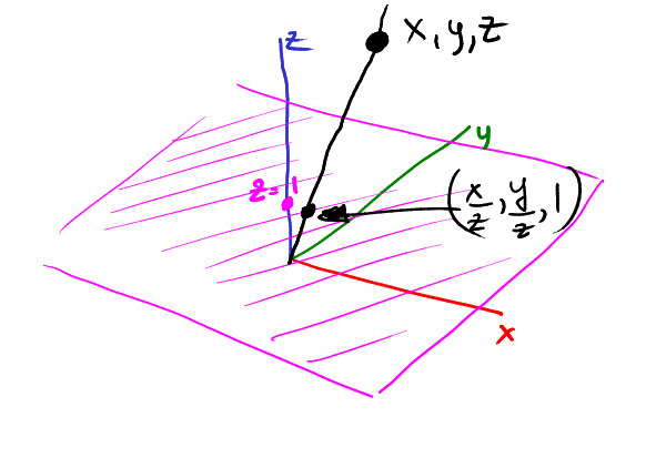
In this picture, our physical plane is purple, and the point (x, y, z) is projected to the point (x / z, y / z):
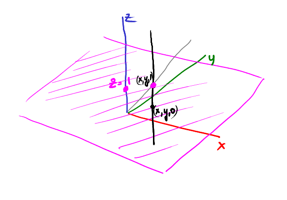
Now, let's imagine a vertical rail passing through a point (x, y, 1). Where is the point projected (x, y, 1)? Of course, in (x, y):
Now let's start sliding down the rail, for example, a point (x, y, 1/2) is projected onto (2x, 2y):

Continue to slide: the point (x, y, 1/4) is projected at (4x, 4y):
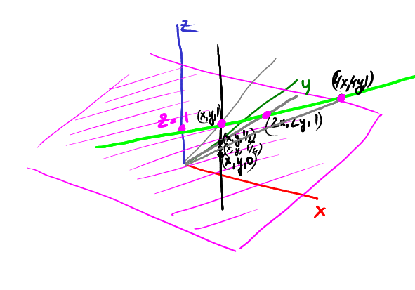
Continuing to slide to zero along z, our projection goes farther and farther from the center of coordinates in the direction (x, y).
That is, the point (x, y, 0) is projected to an infinitely far point in the direction (x, y). What is it? That's right, it's a vector!
Homogeneous coordinates make it possible to distinguish between a vector and a point. If a programmer writes vec2 v (x, y), is it a vector or a dot?
Hard to say. And in homogeneous coordinates, everything with zero over the third component is a vector, everything else is end points.
See: vector + vector = vector. Vector vector = vector. Point + vector = point. Isn't it great?
Compound Transform Example
I have already said that we need to be able to accumulate dozens of transformations. Why? Suppose you need to rotate a flat object around a point (x0, y0). How to do it? You can go and look for formulas, and you can do it yourself, because we have all the tools.
We can rotate around the center of coordinates, we can move. What else does? Shift x0, y0 to the center of coordinates, rotate, return back. Freebie!

In the 3D sequence of actions will be a little longer, but the meaning remains the same: we only need to be able to do several basic transformations, and with their help we can code any complicated thing.
Wait, do I have the right to touch the bottom row of the 3x3 matrix?
And how! Let's apply this conversion:

to our standard test object. I remind you that the test object is white, single x and one vector are shown in red and green, respectively
Here is our converted object:

And here begins the most interesting. Remember our exercise about buffer? Here we will do almost the same thing.
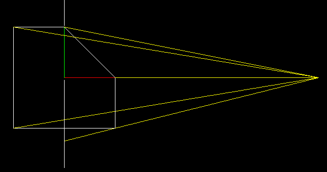
We will project our two-dimensional object onto the x = 0 line. And now let's complicate the task: the projection will be central, our camera is at the point (5, 0) and looks at the origin of coordinates. To find a projection, we must draw lines passing through a camera point and each vertex of our object (yellow lines), and then find their intersection from a straight screen (white vertical).
Now let's remove the original object and instead draw a transformed one.
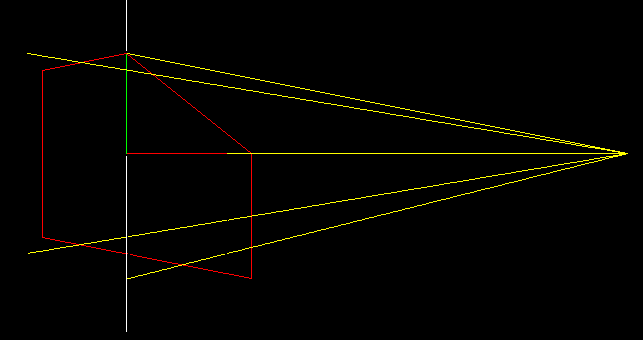
If we use the usual orthogonal projection of our transformed object, then we will find exactly the same points!
What does this mapping do? It each vertical edge leaves vertical, but at the same time stretches those that are close to the camera, and compresses those that are farther from the camera. Having correctly selected the stretch-compression ratio, we can achieve the effect that with a simple orthogonal projection we get an image in perspective distortion! In the next paragraph, we will add one dimension and show where the coefficient -1/5 came from.
It's time to move on to three dimensions.
Let's explain the magic that just happened.
As in the case of two-dimensional affine transformations, we will also use homogeneous coordinates in three-dimensional space.
We take the point (x, y, z), immerse it in four-dimensional space, add one to the fourth component, transform it in four dimensions and project it back into 3d. For example, take the following conversion:

A 3D projection gives the following coordinates:

Well remember this result, but postpone it for a couple of minutes. Let's return to the standard definition of the central projection in the usual 3D, without uniform coordinates and other exotic things. Suppose we have a point P = (x, y, z), which we want to project on the z = 0 plane, the camera is on the z axis at a distance c from the center of coordinates.

We know that the triangles ABC and ODC are similar. That is, we can write | AB | / | AC | = | OD | / | OC | => x / (cz) = x '/ c.

Considering the triangles CPB and CP'D, one can easily come to a similar record for the y coordinate:

So, it is very, very similar to the result of a projection through homogeneous coordinates, only there it was all considered one matrix multiplication. We derived the dependence of the coefficients r = -1 / c.
To consolidate the material: the main formula for today
Although if you just take this formula without understanding the entire previous text, then I hate you. So, if we want to build a central perspective with (important!) A camera located on the z axis at a distance c from the origin , we first immerse three-dimensional points in four-dimensional space, adding 1. Then multiply the following matrix and project the result back to 3D :

We have deformed our object in such a way that now, to build a wire renderer with a perspective, we simply need to forget about the newly received z coordinate. If we want to build a z-buffer, then, of course, we use it. Snapshot code is available on github. The result of his work is visible at the very beginning of our article.
Source: https://habr.com/ru/post/248611/
All Articles