Simple "iron" terminal
This article is a continuation of the description of the microcontroller on the 6502 "Ayush" processor . In it, we will look at how to turn the controller into a full-fledged computer kit, and you don’t have to make Ayusha as a basis, any other device will do. Well, or use the assembled terminal for something else. And again, for the assembly will be applied "grass feed" ...
To begin with, let us recall a little the history of computer engineering in the “pre-micro-RSC” era. In fact, most of the first computers were regular controllers, to which it was necessary to connect a keyboard, a TV set and a program reading / reading device (at that time a punisher or a cassette tape recorder). The collected iron was called the terminal and was divided into two types - “dumb” and intelligent terminals. The second of them was essentially a separate full-fledged computer, had its own processor and could connect to more powerful counterparts. But the first version did not have a processor, was going on a "hard" logic and could only communicate with external devices via a serial port, and therefore was called "stupid". Well, stupid - not stupid, but such a terminal performed its task, especially as there were no special requirements for it.
It was decided to assemble such a terminal for “Ayushi”. It was supposed to allow the output of alphanumeric information received from the controller to a standard TV, enter the program text from the built-in keyboard, and also allow the controller to communicate with a regular tape recorder. Yes, in fact, the assigned tasks smelled like terry downgrading, but apart from them, the finished device could communicate not only with the existing controller, but also be a completely independent network (!, But more on that below) device. And yes, no fans, no noisy things - silence when working!
The scheme of the terminal can be found at the link at the end of the article. Here I will describe the insides of the structure and the reason for their choice.
')
The TV output was made in violation of the 70s canons, using the ATMEGA8 single-chip microcontroller, on which, in principle, the entire terminal could be assembled (such designs exist). But, since single-chip terminals do not allow them to specifically expand on hardware, they use non-canonical PS / 2 keyboards and do not allow working at speeds below 1200 bps, they were decided to refuse and leave the chip to work only on television output. Why on the TV, and not on the VGA-compatible devices - there was a small car TV monitor, which was enough for working with Ayusha.
For keyboard input, it was decided to use an ASCII keyboard. As you know, all modern keyboards, both in homemade and industrial, are built on the basis of a matrix, with subsequent processing of keystrokes by the built-in (or additional) processor. Matrix keyboards were used both in the Spectrum and in the RC-86, and the current AT-keyboards are also matrix ones. However, the first computers, the same Apple-I / II, used ASCII-keyboards that did not take up the processor's computing time and issued a ready-made ASCII code of the pressed character right away, which in my opinion is much more convenient than wasting time on stupid matrix scanning standby pressing. For clever keyboards, specialized chips were previously produced (in fact, a ROM with a table of ASCII codes), in other cases, when it was enough to use the first 128 characters of the table, simple diode coders were used. It was based on Don Lancaster's well-known keyboard, and the chips currently missing in the market were replaced with simple transistor cascades. Now I have an ASCII-keyboard, which is not ashamed to connect to the first Apple.
In the vastness of the country, a set of keys, untouched from Soviet times, was found (thanks to Sergey, R7GW):
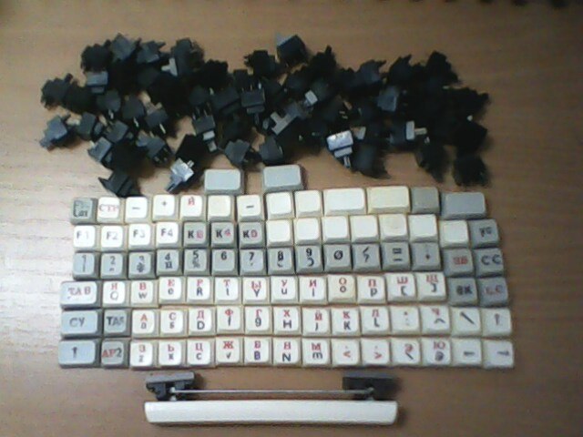
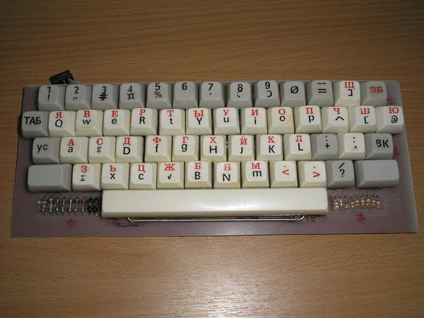
The keys were collected in a heap and placed together with the diode decoders on one board:
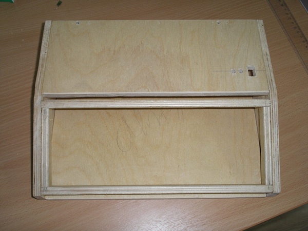
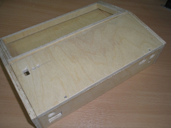
Of course, the construction should work not in principle, but in the case, therefore, the hull sculpting began from pieces of 10 mm plywood:
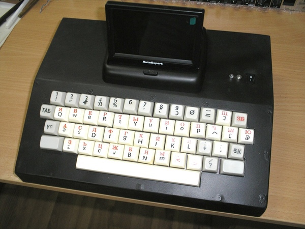
After assembling the case and installing the keyboard into it, the case was painted with the so-called “rubber paint” (rubber paint, essentially dissolved rubber in the cartridge), the necessary connectors and indicators were installed. On the top of the case there are indicators for switching on and reading from a magnetic tape, as well as an input source switch (see below):
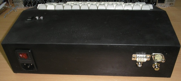
The back wall has a power connector with a switch and a fuse, a COM port, an output for a TV and a tape recorder, and a power connector for a TV or external devices:
In general, I admit that I was somewhat in a hurry with the manufacture of the case, so the heads of the screws and some rough edges that do not affect the overall operation of the terminal are visible.
Since we do not have a processor, a node for converting a parallel code received from a keyboard into a serial code has appeared in the terminal scheme. Having tried several options, it was decided to use as a basis the scheme on the multiplexer 155KP2, and not on the shift registers. It came out easier and consumed less power. You can see the result on the diagram, the link at the end of the article.
The speed of the terminal - 300 bps.
...
I hope everyone laughed and dried their tears, we continue.
...
Why is such a low speed chosen? First, based on the fact that the slowest part of the computer usually sits in front of it and is not able to type text at a speed higher than 33 characters per second. Secondly, to display alphanumeric information on the monitor does not require high speed (in comparison with graphics). Thirdly, we need to somehow communicate with the tape recorder, without using additional software appendages. Well, in the fourth, the unhurried conclusion of the text on the monitor is soothing and somewhat resembles footage from the “Matrix”.
Of course, without using the circuit blocks for interface with a tape recorder, you can raise the speed of the terminal's communication on the COM port to higher speeds (19.2 kbit / s - software limiting the used ATMMEGI firmware) without changing the main circuit. Thus, the terminal can be connected to configure any device on the COM port - modems, tsisok, routers, etc., of course, in cases when updating the device firmware is not required.
The tape recorder uses the Kansas tape recording standard . In this case, "0" is encoded with a frequency of 2400 Hertz, and "1" is 1200 Hertz. These frequencies are perfectly recorded both on a magnetic tape and on solid-state drives, and are much less susceptible to failures than the NRZ code used in the same Micro-80 / RK-86. For reading from the tape, a frequency comparator is used, at the output of which we get a serial data stream. As was seen in the previous photo, we can choose the input source switch from where the controller will receive information - from the keyboard or from the tape, it will be absolutely indifferent to it. We get a sort of driver-free communication unit of the controller with a magnetic tape, which also does not use processor resources.
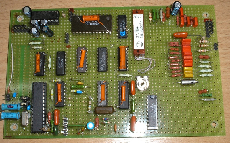
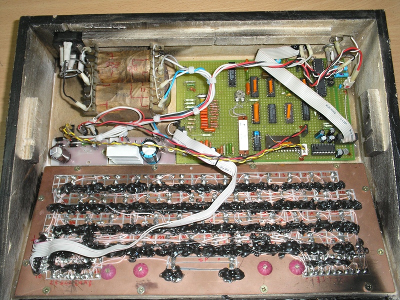
View of the terminal board is attached. On the reverse side - MGTF is again mated, but this is not interesting, therefore, I don’t show it. The transistor keys related to the keyboard are located on the right side of the board.
Internal view of the terminal - all components in a wooden case.
How is the procedure for downloading the program from the magnetic tape can be viewed on the attached video. The demo converter is loaded from decimal to hexadecimal and vice versa. It should be noted that the download of the program itself contains some game moment, simultaneously allowing to evaluate the correctness of the work (thanks to inghost ).
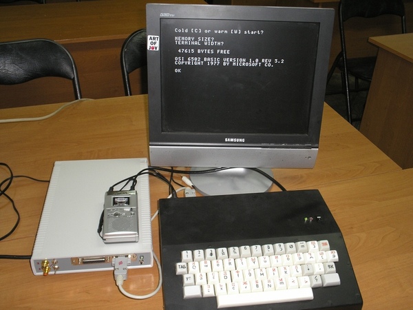
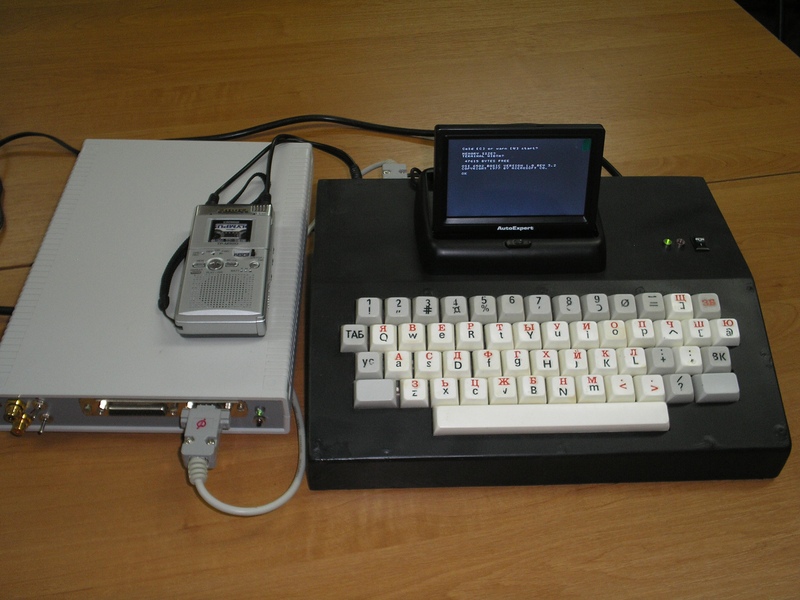
Summarize the view of the complex controller - terminal can be on the following photos, as with a conventional TV (photo at the beginning of the article), and with the car (here we use a micro cassette tape recorder, unlike the previous video).
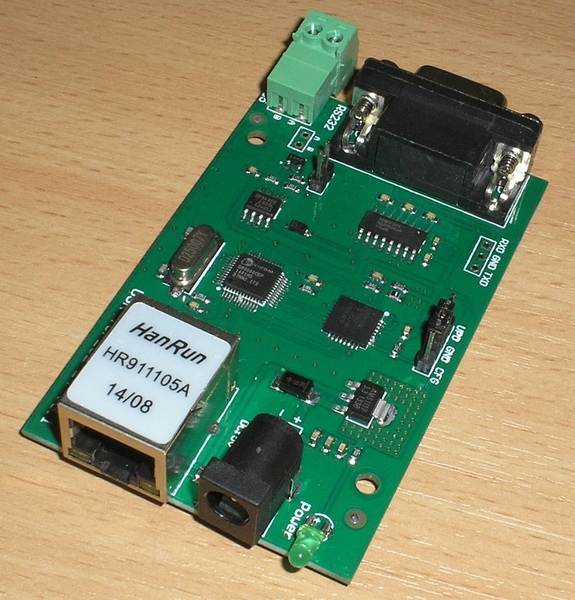
The terminal was tested for networking using the COM-> ETH converter bought on Aliexpress.
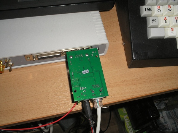
Using the second converter and forwarding ports in the router, it was possible to control Ayusha via the Internet. Although nothing prevents us in the same way to control any other devices through a virtual or real COM port.
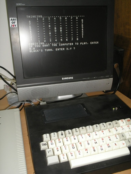
Well, to end the conversation. On “Ayusha it is already possible to play, on the photo screen of the launched program“ Reversi ”. And since the controller has already acquired a real-time clock chip , it is already possible not only to play for a while, but also to use it in complex control devices.
Thank you for understanding.
References
The article by Don Lancaster in the April issue of Popular Electronics magazine in 1974 about building an ASCII keyboard
ASCII keyboard terminal layout
Terminal layout
Project main page
Vkontakte community
To begin with, let us recall a little the history of computer engineering in the “pre-micro-RSC” era. In fact, most of the first computers were regular controllers, to which it was necessary to connect a keyboard, a TV set and a program reading / reading device (at that time a punisher or a cassette tape recorder). The collected iron was called the terminal and was divided into two types - “dumb” and intelligent terminals. The second of them was essentially a separate full-fledged computer, had its own processor and could connect to more powerful counterparts. But the first version did not have a processor, was going on a "hard" logic and could only communicate with external devices via a serial port, and therefore was called "stupid". Well, stupid - not stupid, but such a terminal performed its task, especially as there were no special requirements for it.
It was decided to assemble such a terminal for “Ayushi”. It was supposed to allow the output of alphanumeric information received from the controller to a standard TV, enter the program text from the built-in keyboard, and also allow the controller to communicate with a regular tape recorder. Yes, in fact, the assigned tasks smelled like terry downgrading, but apart from them, the finished device could communicate not only with the existing controller, but also be a completely independent network (!, But more on that below) device. And yes, no fans, no noisy things - silence when working!
The scheme of the terminal can be found at the link at the end of the article. Here I will describe the insides of the structure and the reason for their choice.
')
The TV output was made in violation of the 70s canons, using the ATMEGA8 single-chip microcontroller, on which, in principle, the entire terminal could be assembled (such designs exist). But, since single-chip terminals do not allow them to specifically expand on hardware, they use non-canonical PS / 2 keyboards and do not allow working at speeds below 1200 bps, they were decided to refuse and leave the chip to work only on television output. Why on the TV, and not on the VGA-compatible devices - there was a small car TV monitor, which was enough for working with Ayusha.
For keyboard input, it was decided to use an ASCII keyboard. As you know, all modern keyboards, both in homemade and industrial, are built on the basis of a matrix, with subsequent processing of keystrokes by the built-in (or additional) processor. Matrix keyboards were used both in the Spectrum and in the RC-86, and the current AT-keyboards are also matrix ones. However, the first computers, the same Apple-I / II, used ASCII-keyboards that did not take up the processor's computing time and issued a ready-made ASCII code of the pressed character right away, which in my opinion is much more convenient than wasting time on stupid matrix scanning standby pressing. For clever keyboards, specialized chips were previously produced (in fact, a ROM with a table of ASCII codes), in other cases, when it was enough to use the first 128 characters of the table, simple diode coders were used. It was based on Don Lancaster's well-known keyboard, and the chips currently missing in the market were replaced with simple transistor cascades. Now I have an ASCII-keyboard, which is not ashamed to connect to the first Apple.
In the vastness of the country, a set of keys, untouched from Soviet times, was found (thanks to Sergey, R7GW):
The keys were collected in a heap and placed together with the diode decoders on one board:
Of course, the construction should work not in principle, but in the case, therefore, the hull sculpting began from pieces of 10 mm plywood:
After assembling the case and installing the keyboard into it, the case was painted with the so-called “rubber paint” (rubber paint, essentially dissolved rubber in the cartridge), the necessary connectors and indicators were installed. On the top of the case there are indicators for switching on and reading from a magnetic tape, as well as an input source switch (see below):
The back wall has a power connector with a switch and a fuse, a COM port, an output for a TV and a tape recorder, and a power connector for a TV or external devices:
In general, I admit that I was somewhat in a hurry with the manufacture of the case, so the heads of the screws and some rough edges that do not affect the overall operation of the terminal are visible.
Since we do not have a processor, a node for converting a parallel code received from a keyboard into a serial code has appeared in the terminal scheme. Having tried several options, it was decided to use as a basis the scheme on the multiplexer 155KP2, and not on the shift registers. It came out easier and consumed less power. You can see the result on the diagram, the link at the end of the article.
The speed of the terminal - 300 bps.
...
I hope everyone laughed and dried their tears, we continue.
...
Why is such a low speed chosen? First, based on the fact that the slowest part of the computer usually sits in front of it and is not able to type text at a speed higher than 33 characters per second. Secondly, to display alphanumeric information on the monitor does not require high speed (in comparison with graphics). Thirdly, we need to somehow communicate with the tape recorder, without using additional software appendages. Well, in the fourth, the unhurried conclusion of the text on the monitor is soothing and somewhat resembles footage from the “Matrix”.
Of course, without using the circuit blocks for interface with a tape recorder, you can raise the speed of the terminal's communication on the COM port to higher speeds (19.2 kbit / s - software limiting the used ATMMEGI firmware) without changing the main circuit. Thus, the terminal can be connected to configure any device on the COM port - modems, tsisok, routers, etc., of course, in cases when updating the device firmware is not required.
The tape recorder uses the Kansas tape recording standard . In this case, "0" is encoded with a frequency of 2400 Hertz, and "1" is 1200 Hertz. These frequencies are perfectly recorded both on a magnetic tape and on solid-state drives, and are much less susceptible to failures than the NRZ code used in the same Micro-80 / RK-86. For reading from the tape, a frequency comparator is used, at the output of which we get a serial data stream. As was seen in the previous photo, we can choose the input source switch from where the controller will receive information - from the keyboard or from the tape, it will be absolutely indifferent to it. We get a sort of driver-free communication unit of the controller with a magnetic tape, which also does not use processor resources.
View of the terminal board is attached. On the reverse side - MGTF is again mated, but this is not interesting, therefore, I don’t show it. The transistor keys related to the keyboard are located on the right side of the board.
Internal view of the terminal - all components in a wooden case.
How is the procedure for downloading the program from the magnetic tape can be viewed on the attached video. The demo converter is loaded from decimal to hexadecimal and vice versa. It should be noted that the download of the program itself contains some game moment, simultaneously allowing to evaluate the correctness of the work (thanks to inghost ).
Summarize the view of the complex controller - terminal can be on the following photos, as with a conventional TV (photo at the beginning of the article), and with the car (here we use a micro cassette tape recorder, unlike the previous video).
The terminal was tested for networking using the COM-> ETH converter bought on Aliexpress.
Using the second converter and forwarding ports in the router, it was possible to control Ayusha via the Internet. Although nothing prevents us in the same way to control any other devices through a virtual or real COM port.
Well, to end the conversation. On “Ayusha it is already possible to play, on the photo screen of the launched program“ Reversi ”. And since the controller has already acquired a real-time clock chip , it is already possible not only to play for a while, but also to use it in complex control devices.
Thank you for understanding.
References
The article by Don Lancaster in the April issue of Popular Electronics magazine in 1974 about building an ASCII keyboard
ASCII keyboard terminal layout
Terminal layout
Project main page
Vkontakte community
Source: https://habr.com/ru/post/248379/
All Articles