PLC100 + LabVIEW + joystick
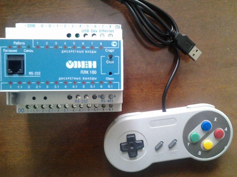
Once on my desktop there was a usb-joystick and a PLC (programmable logic controller) of the firm ARIES-PLC100, while the LabVIEW environment was running on the computer. I thought that all this - at least for fun - can be combined by organizing the control of the PLC (its outputs) using the joystick buttons (later I decided to use not just buttons, but their combinations - DOWN, FORWARD, Y, for example).
So, how it all works. LabVIEW processes the joystick keystroke and transmits the keystroke information to the PLC100 (in this case, via the serial port); PLC100, in accordance with the program loaded into it, reacts to certain key combinations by turning on / off its outputs.
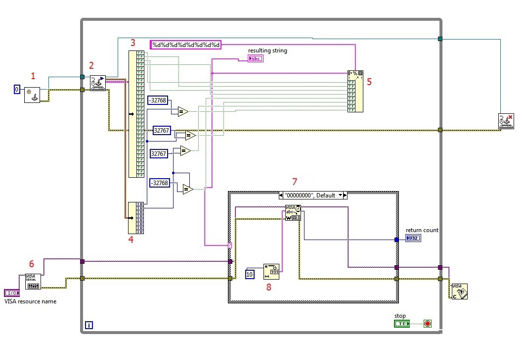
The program that handles the pressing of the joystick buttons and transmits information about them to the PLC100, in general, looks like this:
')
Now in more detail.
1 - Initialize the joystick. You can find it in the Function Palette in the Connectivity-> Input Device Control section. If one joystick is connected to the computer, as in my case, it is recommended to equate the Device Index parameter to 0.
2 - Receive data from the input device. The data on the buttons and axes directions (cross) is stored in clusters, which with the help of the Unbundle function must be broken down into elements in order to process them in the future. The “button” cluster 3 (in the figure it is already broken into elements) consists of boolean elements; when the button is pressed, the corresponding cluster element is set to TRUE. With the “axial” cluster 4, the situation is slightly different: it consists of integer elements, and when the UP key is pressed, the first element of the cluster, X axis, takes the value -32768, the DOWN key corresponds to 32767. With the second element of the cluster, Y axis — approximately also: BACK = -32768, FORWARD = 32767.
5 - Forming a string. The Format Into String function forms (or returns) a string from elements of different data types. In my case, these are Boolean elements and there are only 8 of them, so the output will be a string of 8 characters. An explanation is required here: if no button is pressed, the line has the form "00000000"; if, for example, the button 1 is pressed, the line will be such “1000000”, if the button is 2, then such “01000000”, etc. Depending on the value of this string, a specific number will be written to the serial port, which will already process the PLC100. By the way, the “format string” parameter of the Format Into String function is set to “% d% d% d% d% d% d% d% d” to convert the input boolean FALSE and TRUE to zeros and ones and eventually get a string like for example, “10,000,000”, not “TRUEFALSEFALSEFALSE ...”. Like this. Can it be easier? It is possible, but at another time.
6 - Configuring and opening the serial port. I left all the default settings, adding only the control to select the port number. To work with a COM port, NI-VISA must be installed (here www.ni.com/download/ni-visa-5.4.1/4626/en ).
7 - Case structure. Depending on the value of the string formed by the Format Into String function, it writes a number to the serial port (11, for example, corresponds to button 1, 12 to button 2, etc.). This number is previously converted by the Number To Decimal String function - figure 8 in the figure (without this block, for some unknown reason, PLC100 read some kind of gibberish from the port).
A little about the ports of the PLC100. As many as three connectors can work as a COM port: these are Debug-232 on the front panel, RS-232 and RS-485 below. When opening the port, you will need to specify its number: for Debug-232 it is 4, for RS-232 - 1, for RS-485 - 0. I used RS-485, connecting the PLC to the computer via a cheap Chinese RS-485 adapter -> USB (on the photo), respectively, in the program as the port number is 0.

PLC100 is programmed in the Codesys 2.3 environment. In addition, you need the so-called target - something like a file with a description of the configuration of the programmable device. To initialize and open the port, I used the ComService.lib library (the library and an example of it can be downloaded here www.owen.ru/forum/showthread.php?t=551&page=6 ). I combined the configuration and opening of the port in one functional block - see the figure below.

You can see that the 'set' object is declared as COMSETTINGS. This is an instance of the COMSETTINGS structure containing the port settings; it is already declared in the ComService library (to be exact, in the SysComLib library, which is part of the ComService). The settings are fairly standard, just turn to set. Port = 0 - this is RS-485, which was mentioned above.
The COM_SERVICE function block has two parameters: the first is the name of the COMSETTINGS structure, the second is the type of operation, where 0 corresponds to the setting and opening.
Next, using the SysComRead function, included in the SysLibCom library, we read the data from the port. DwHandle is the port number (RS-485 in this case), dwBufferAddress is a pointer to the variable where the data will be read, dwBytesToRead is the number of bytes read (in my case it is 2), dwTimeout is the time in ms, after which the function must complete; if you put too little, the function simply does not read anything.

Next comes the conversion of the string read from the port into an integer and the comparison of this number: if it is, for example, 10, then no button is pressed, if 11, then X is pressed, etc.
To process the key combinations, I programmed 6 function blocks - 3 to switch on the first three relay outputs of the PLC (I think three outputs will be enough for the beginning) and 3 to turn them off; Four combinations of 3 keys and two of 4. Inside these blocks look like this:

i1, i2, i3 are the first, second and third buttons of the combination, respectively. The functional block for a four-button combination is not much different, and getting it from a three-button is a matter of technique, so I omit its content.
It should be added that for each functional block I announced my own copies of the R_TRIG, TON and TOF blocks, because all three outputs would react to one combination. But for the units on and off the same output, I left them the same.
As a result, the program I looked like (I miss the place with the opening of the port):

The video shows how the LEDs light up on the PLC, indicating that the output is active. For clarity, I would like as a load to connect to the outputs at least a light bulb or starter, but at the time of recording video at hand there was only a computer cooler.
I must say that the whole system (I say “system”, because I don’t know exactly where the “jam” was) to the quick clicks, reacted rather reluctantly, if at all; unhurried clicks (like in the video) improve the situation a little, but sometimes the reaction to them was absent. But the PLC100 also has an Ethernet connector. So next time I will try to make at least a small improvement by linking the PLC to LabVIEW via an OPC server via Ethernet.
Thanks for attention.
So, how it all works. LabVIEW processes the joystick keystroke and transmits the keystroke information to the PLC100 (in this case, via the serial port); PLC100, in accordance with the program loaded into it, reacts to certain key combinations by turning on / off its outputs.
LabVIEW part
The program that handles the pressing of the joystick buttons and transmits information about them to the PLC100, in general, looks like this:
')
Now in more detail.
1 - Initialize the joystick. You can find it in the Function Palette in the Connectivity-> Input Device Control section. If one joystick is connected to the computer, as in my case, it is recommended to equate the Device Index parameter to 0.
2 - Receive data from the input device. The data on the buttons and axes directions (cross) is stored in clusters, which with the help of the Unbundle function must be broken down into elements in order to process them in the future. The “button” cluster 3 (in the figure it is already broken into elements) consists of boolean elements; when the button is pressed, the corresponding cluster element is set to TRUE. With the “axial” cluster 4, the situation is slightly different: it consists of integer elements, and when the UP key is pressed, the first element of the cluster, X axis, takes the value -32768, the DOWN key corresponds to 32767. With the second element of the cluster, Y axis — approximately also: BACK = -32768, FORWARD = 32767.
5 - Forming a string. The Format Into String function forms (or returns) a string from elements of different data types. In my case, these are Boolean elements and there are only 8 of them, so the output will be a string of 8 characters. An explanation is required here: if no button is pressed, the line has the form "00000000"; if, for example, the button 1 is pressed, the line will be such “1000000”, if the button is 2, then such “01000000”, etc. Depending on the value of this string, a specific number will be written to the serial port, which will already process the PLC100. By the way, the “format string” parameter of the Format Into String function is set to “% d% d% d% d% d% d% d% d” to convert the input boolean FALSE and TRUE to zeros and ones and eventually get a string like for example, “10,000,000”, not “TRUEFALSEFALSEFALSE ...”. Like this. Can it be easier? It is possible, but at another time.
6 - Configuring and opening the serial port. I left all the default settings, adding only the control to select the port number. To work with a COM port, NI-VISA must be installed (here www.ni.com/download/ni-visa-5.4.1/4626/en ).
7 - Case structure. Depending on the value of the string formed by the Format Into String function, it writes a number to the serial port (11, for example, corresponds to button 1, 12 to button 2, etc.). This number is previously converted by the Number To Decimal String function - figure 8 in the figure (without this block, for some unknown reason, PLC100 read some kind of gibberish from the port).
PLC program
A little about the ports of the PLC100. As many as three connectors can work as a COM port: these are Debug-232 on the front panel, RS-232 and RS-485 below. When opening the port, you will need to specify its number: for Debug-232 it is 4, for RS-232 - 1, for RS-485 - 0. I used RS-485, connecting the PLC to the computer via a cheap Chinese RS-485 adapter -> USB (on the photo), respectively, in the program as the port number is 0.
PLC100 is programmed in the Codesys 2.3 environment. In addition, you need the so-called target - something like a file with a description of the configuration of the programmable device. To initialize and open the port, I used the ComService.lib library (the library and an example of it can be downloaded here www.owen.ru/forum/showthread.php?t=551&page=6 ). I combined the configuration and opening of the port in one functional block - see the figure below.
You can see that the 'set' object is declared as COMSETTINGS. This is an instance of the COMSETTINGS structure containing the port settings; it is already declared in the ComService library (to be exact, in the SysComLib library, which is part of the ComService). The settings are fairly standard, just turn to set. Port = 0 - this is RS-485, which was mentioned above.
The COM_SERVICE function block has two parameters: the first is the name of the COMSETTINGS structure, the second is the type of operation, where 0 corresponds to the setting and opening.
Next, using the SysComRead function, included in the SysLibCom library, we read the data from the port. DwHandle is the port number (RS-485 in this case), dwBufferAddress is a pointer to the variable where the data will be read, dwBytesToRead is the number of bytes read (in my case it is 2), dwTimeout is the time in ms, after which the function must complete; if you put too little, the function simply does not read anything.
Next comes the conversion of the string read from the port into an integer and the comparison of this number: if it is, for example, 10, then no button is pressed, if 11, then X is pressed, etc.
To process the key combinations, I programmed 6 function blocks - 3 to switch on the first three relay outputs of the PLC (I think three outputs will be enough for the beginning) and 3 to turn them off; Four combinations of 3 keys and two of 4. Inside these blocks look like this:
i1, i2, i3 are the first, second and third buttons of the combination, respectively. The functional block for a four-button combination is not much different, and getting it from a three-button is a matter of technique, so I omit its content.
It should be added that for each functional block I announced my own copies of the R_TRIG, TON and TOF blocks, because all three outputs would react to one combination. But for the units on and off the same output, I left them the same.
As a result, the program I looked like (I miss the place with the opening of the port):
The video shows how the LEDs light up on the PLC, indicating that the output is active. For clarity, I would like as a load to connect to the outputs at least a light bulb or starter, but at the time of recording video at hand there was only a computer cooler.
I must say that the whole system (I say “system”, because I don’t know exactly where the “jam” was) to the quick clicks, reacted rather reluctantly, if at all; unhurried clicks (like in the video) improve the situation a little, but sometimes the reaction to them was absent. But the PLC100 also has an Ethernet connector. So next time I will try to make at least a small improvement by linking the PLC to LabVIEW via an OPC server via Ethernet.
Thanks for attention.
Source: https://habr.com/ru/post/248357/
All Articles