Hexapod-robot controlled from PC
After viewing a large number of articles and videos about spider robots, I wanted to create one myself. It was decided to do everything from scratch, that is, to create a robot body, solder the board and program it.
The body of the robot was decided to be made of Plexiglas, this material is easy to process and quite durable. The shape of the limbs and the body of the robot created independently of existing analogues. I apologize for the insufficient number of sizes on the drawings, I drew for myself.
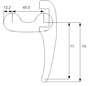
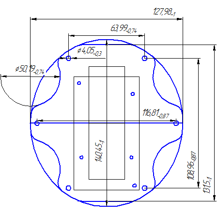
All parts were cut from 3 mm thick plexiglas with a jigsaw. To make it look prettier, all parts were covered with carbon film. Next, it was necessary to choose a servos. It was decided to design the use of MG90S servos.
')

These are the cheapest servos with metal gears. At the time of purchase, they were 200 rubles apiece. As a result, the assembly of the hull and servos turned out this.

It was decided to build the whole system on two AVR ATmega 32 microcontrollers, the choice was justified by the fact that I had these stones, and the use of two at once is explained by the fact that it would be difficult for one to cope with all the tasks that the robot must perform. Namely:
- movement in any direction, as well as rotation around its axis in any direction;
- keeping the horizon on an inclined surface;
- impossibility of collision with static objects during movement.
Thus, one microcontroller receives commands from the user via the radio channel, receives and processes information from sensors (range finder, accelerometer), sends commands to the second microcontroller and sends data requested by the user from a personal computer. The second microcontroller receives commands from the first microcontroller and controls the movement of the servos with the help of pulse-width modulation. As a result, the idea can be reflected in the structural scheme.

The popular ultrasonic distance sensor HC-SR04 was used as a range finder.

The MMA7361 sensor was used as an accelerometer. It is a low-power, capacitive microelectromechanical acceleration sensor in a low-profile package, featuring a unipolar low-frequency filter, temperature compensation and self-test circuitry, a zero acceleration detector for determining linear free fall and a choice of two acceleration levels. The zero-acceleration voltage level and sensitivity are factory-set and do not require additional external components. MMA7361 has a sleep mode.

These sensors are inexpensive and convenient to use at home.
It remained to determine how to connect the PC and the robot. It was decided to use the radio. As a result, a set of 3DRobotics radio modems was purchased.

So, having collected all the necessary hardware, it was necessary to create a board. In developing the concept it was necessary to take into account the power of all nodes in the system. The power supply to the servos must be separated from the power supply of the rest of the circuit in order to avoid interference with the operation of microcontrollers and sensors.
According to the calculations, it was found that with the active operation of all servo drives, the maximum current in the circuit is three amperes. For greater reliability, it was decided to divide the power of the servos into two parts. Also, according to calculations, it became clear that with the active work of microcontrollers and sensors, their consumption will not exceed one ampere. Thus, the maximum current in the circuit will be one and a half amperes.
A battery of 7.4 volts was available. In the scheme, it was necessary to provide two voltage regulators from 7.4 to 5 volts with a load current of three amperes to power the actuators and one voltage regulator from 7.4 to 5 volts with a load current of one ampere to power the rest of the circuit. To solve this problem, Chinese stabilizers KIS-3R33S were used, since they also already had them.

Next was developed fee.

Made by laser-iron method, etched in ferric chloride and tinned with Rosa alloy

Then everything was neatly soldered.
During the assembly process, it was decided to add another camera. The result was this.

Next, programs for microcontrollers and a simple program for PCs were written. The program interface for the PC looks like this, with the help of this program the robot is controlled and debugged its movements.

Holding the horizon is not ready yet, so the program displays only the angles of inclination. Also, the program has not yet bolted the video broadcast, the video can only be viewed using the standard program that came with the camera.
Well, that's all for now, the robot goes and stops in front of the obstacles, the robot goes to the video not quite straightforward, because its legs slip, you need to equip them with something clinging.
The body of the robot was decided to be made of Plexiglas, this material is easy to process and quite durable. The shape of the limbs and the body of the robot created independently of existing analogues. I apologize for the insufficient number of sizes on the drawings, I drew for myself.
All parts were cut from 3 mm thick plexiglas with a jigsaw. To make it look prettier, all parts were covered with carbon film. Next, it was necessary to choose a servos. It was decided to design the use of MG90S servos.
')
These are the cheapest servos with metal gears. At the time of purchase, they were 200 rubles apiece. As a result, the assembly of the hull and servos turned out this.
It was decided to build the whole system on two AVR ATmega 32 microcontrollers, the choice was justified by the fact that I had these stones, and the use of two at once is explained by the fact that it would be difficult for one to cope with all the tasks that the robot must perform. Namely:
- movement in any direction, as well as rotation around its axis in any direction;
- keeping the horizon on an inclined surface;
- impossibility of collision with static objects during movement.
Thus, one microcontroller receives commands from the user via the radio channel, receives and processes information from sensors (range finder, accelerometer), sends commands to the second microcontroller and sends data requested by the user from a personal computer. The second microcontroller receives commands from the first microcontroller and controls the movement of the servos with the help of pulse-width modulation. As a result, the idea can be reflected in the structural scheme.
The popular ultrasonic distance sensor HC-SR04 was used as a range finder.
The MMA7361 sensor was used as an accelerometer. It is a low-power, capacitive microelectromechanical acceleration sensor in a low-profile package, featuring a unipolar low-frequency filter, temperature compensation and self-test circuitry, a zero acceleration detector for determining linear free fall and a choice of two acceleration levels. The zero-acceleration voltage level and sensitivity are factory-set and do not require additional external components. MMA7361 has a sleep mode.
These sensors are inexpensive and convenient to use at home.
It remained to determine how to connect the PC and the robot. It was decided to use the radio. As a result, a set of 3DRobotics radio modems was purchased.
So, having collected all the necessary hardware, it was necessary to create a board. In developing the concept it was necessary to take into account the power of all nodes in the system. The power supply to the servos must be separated from the power supply of the rest of the circuit in order to avoid interference with the operation of microcontrollers and sensors.
According to the calculations, it was found that with the active operation of all servo drives, the maximum current in the circuit is three amperes. For greater reliability, it was decided to divide the power of the servos into two parts. Also, according to calculations, it became clear that with the active work of microcontrollers and sensors, their consumption will not exceed one ampere. Thus, the maximum current in the circuit will be one and a half amperes.
A battery of 7.4 volts was available. In the scheme, it was necessary to provide two voltage regulators from 7.4 to 5 volts with a load current of three amperes to power the actuators and one voltage regulator from 7.4 to 5 volts with a load current of one ampere to power the rest of the circuit. To solve this problem, Chinese stabilizers KIS-3R33S were used, since they also already had them.
Next was developed fee.
Made by laser-iron method, etched in ferric chloride and tinned with Rosa alloy
Then everything was neatly soldered.
During the assembly process, it was decided to add another camera. The result was this.
Next, programs for microcontrollers and a simple program for PCs were written. The program interface for the PC looks like this, with the help of this program the robot is controlled and debugged its movements.
Holding the horizon is not ready yet, so the program displays only the angles of inclination. Also, the program has not yet bolted the video broadcast, the video can only be viewed using the standard program that came with the camera.
Well, that's all for now, the robot goes and stops in front of the obstacles, the robot goes to the video not quite straightforward, because its legs slip, you need to equip them with something clinging.
Source: https://habr.com/ru/post/248335/
All Articles