Autonomous security and surveillance system on the Raspberry PI
Having played with the Raspberry Pi and the camera for it, I thought about its practical application. Just by this time, the need for an autonomous monitoring system with security functions for the dacha had matured (the neglected children of the neighborhood burned a bath at the dacha as a result of alcohol gathering and smoking).
Perhaps my experience and work ( an SD image with all customized software ) will be useful.
Video on the ground did not shoot. For the winter, I did not dare to leave it at an unguarded dacha with roads covered with snow.
')
Some pieces of work in greenhouse conditions:
The project was not customized. He did it exclusively for himself and his own pleasure. From working with video offline via a modem refused immediately. Video via modem in mode even in 3G is not serious.
Project input restrictions:
Input requirements that I formulated for myself:
With the exception of the circular review, all the other requirements were implemented.

Fully circular review failed. Experiments have shown that supplying current through a pair of “brushes from a drill electric motor + current collection from foiled polystyrene material” is clearly not the best idea. Approximately within 2-5 of a 360-degree rotation, a power failure occurs and a reboot occurs. Adding high capacity electrolyte did not help much. As a result, I put two limiters on the rotation angle of 270 degrees and recorded directly without a current collector.
I did not make a photo of the construction with brushes, but I experimented with it a lot. In the photo you can understand how it looked originally (brushes and collector rings made of foiled PCB were removed).
Experiment with other types of current collectors did not. For my purposes and the installation location, a 270 degree view is sufficient (building angle).
Conclusion: the “carbon brush + copper plane” current collection is only suitable for cases when the short contact loss is not critical and where the contact will be restored by inertia.

For turning involved cheap stepper motors. According to the passport, they work from 12V, but as practice has shown, and at 19V they do not heat up in the “1 minute after 3 minutes without holding mode” mode. The UN2003 driver copes with current at 19V even in the SO16 (SMD) package without overheating. With regular UN2003 drivers in a DIP package, which are sold in a set for the step-drivers, there should be no problems at all.
The rotation is smooth and completely silent.
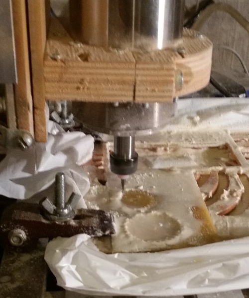
Involute gears with a 1mm module, if anyone is interested, they are very well cut on a CNC machine with a 1mm mill from fiberglass.
The choice of stepper motors is due to the simplicity of control and positioning accuracy during autonomous operation.
For setting to “0” I intended to use a reed switch with a magnet, but after rejecting the circular view, I came to the conclusion that the following technology is more convenient:
Positioning to “0” in this way is rather slow, but still faster than loading Linux. The Linux download speed on raspberries is simply depressing.
As it has been said many times, raspberries are well VERY picky about nutrition. I powered it and WiFi USB from the 19V 2.6A power supply (which was) from the old laptop via the stepdown DC-DC converter. A separate stepdown DC-DC converter was needed to power the 3G modem.
It was impossible to power the modem from one converter and the board did not work, although according to the “Chinese passport” the current of the DC-DC module should suffice. The current in the statics of one converter is enough, but when you activate the modem, you hear how the generation in the voltage converter module fails, going into the audio range, and the output voltage cuts off with the Linux reboot.
Native camera Rasberry Pi c replacement lens. The lens came from the module MT9D111, bought a long time on e-bay for experiments. The matrix was not useful, and the lens went perfectly. Together with the standard lens, the IR-filter built into it also appeared. What is even good, since the new lens is marked with IR. The colors in the pictures are somewhat distorted (pinkish shots), but for that IR backlighting is possible.
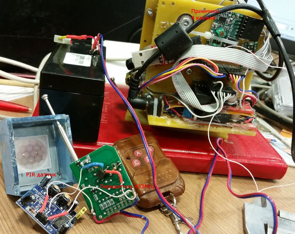
The sensor used is the PIR module on the BISS0001. 433 MHz keychain transmitter, slightly finished (one bipolar transistor and resistor) and controlled by the output from the PIR module.
Experiments have shown that this combination works from 12V acid battery for at least 2 months (maybe more, I have not tried it).
The receiver is 4-channel and is sold complete with a keychain. Thus, 4 zones of protection are provided with the ability to make a photo of the place of operation.
The range of the transmitter-receiver set is less than that stated by the sellers, and the reception is not stable at approximately 40 meters of direct line of sight. Perhaps this is interference from Raspberry pi, GSM modem and / or DC-DC converters.
In the summer, some nights, there were "false" triggers. Probably on birds or bats.
The first version of the sensor was with a separate output to activate the IR backlight. The photo then did not, but there is nothing difficult. Just another transistor controlled from the PIR output. The backlight is a circular board from a 12V surveillance camera with IR LEDs.
After the samples, the local IR illumination of the sensor area refused:
The signal from the sensor:
A lot of detailed articles are devoted to the settings of a 3g modem, WiFi, etc., and I consider it irrational to repeat them.
SD image with everything
customized software .
The file /home/pi/read.me contains links to files where you need to register your passwords.
Configured to Yandex services (e-mail and cloud disk).
Login / password of the console and ftp - standard: “pi / raspberry”
Potential room for improvement (in my opinion):
Standard components:
Solder:
Who has a CNC machine - without problems, you can draw and cut out the body / gears. Draw and cut can be a maximum of 3 hours. I do not post my original drawing. Would do the second time - would do differently and more compactly.
If I needed to make a replicable industrial solution for a similar security alarm task, then I would not choose Raspberry Pi.
Would take an OEM camera module, an STM32 type controller ... with a camera interface and an OEM GSM modem module.
As for me, it is more convenient for me to do such things without OS at all or on specialized OS.
Time to develop the functionality of a pure security alarm would take a maximum of 3-4 times more than pairing a heap of free software with redundant functionality and bringing the entire zoo to a working state.
The power consumption of raspberries and fastidiousness to nutrition are simply depressing.
And so raspberry pi toy is interesting. But just play. Although this is my personal opinion and I do not impose it.
Perhaps my experience and work ( an SD image with all customized software ) will be useful.
Video on the ground did not shoot. For the winter, I did not dare to leave it at an unguarded dacha with roads covered with snow.
')
Some pieces of work in greenhouse conditions:
The project was not customized. He did it exclusively for himself and his own pleasure. From working with video offline via a modem refused immediately. Video via modem in mode even in 3G is not serious.
Project input restrictions:
- Low-speed Internet via GSM modem (MTS). At best, 2G;
- No host with “white IP”;
- Only readily available components.
Input requirements that I formulated for myself:
- Autonomous work with overload after power failure and software failures;
- Turntable (horizontal + vertical) with a circular view;
- Long-focus lens;
- External autonomous sensors with a radio channel;
- Automatic shooting zone sensor;
- Sending Alarm SMS;
- Sending Alarm + low / medium resolution photo to e-mail;
- Background high resolution photo upload to a cloud drive;
- Background upload logs to a cloud drive;
- Management via e-mail (sending bash scripts and getting the results of their execution);
- Management via SMS. Call predefined scripts. For example, turn the camera and take a picture;
- Forwarding SMS arriving on the modem by e-mail;
- Additional functionality when staying nearby, within sustainable WiFi (15-20m):
- Functions WiFi router with the distribution of the Internet;
- Access via ftp and ssh console;
- Web video stream from camera.
With the exception of the circular review, all the other requirements were implemented.
Circular horizontal view
Fully circular review failed. Experiments have shown that supplying current through a pair of “brushes from a drill electric motor + current collection from foiled polystyrene material” is clearly not the best idea. Approximately within 2-5 of a 360-degree rotation, a power failure occurs and a reboot occurs. Adding high capacity electrolyte did not help much. As a result, I put two limiters on the rotation angle of 270 degrees and recorded directly without a current collector.
I did not make a photo of the construction with brushes, but I experimented with it a lot. In the photo you can understand how it looked originally (brushes and collector rings made of foiled PCB were removed).
Experiment with other types of current collectors did not. For my purposes and the installation location, a 270 degree view is sufficient (building angle).
Conclusion: the “carbon brush + copper plane” current collection is only suitable for cases when the short contact loss is not critical and where the contact will be restored by inertia.
Swivel platform.
For turning involved cheap stepper motors. According to the passport, they work from 12V, but as practice has shown, and at 19V they do not heat up in the “1 minute after 3 minutes without holding mode” mode. The UN2003 driver copes with current at 19V even in the SO16 (SMD) package without overheating. With regular UN2003 drivers in a DIP package, which are sold in a set for the step-drivers, there should be no problems at all.
The rotation is smooth and completely silent.
Involute gears with a 1mm module, if anyone is interested, they are very well cut on a CNC machine with a 1mm mill from fiberglass.
The choice of stepper motors is due to the simplicity of control and positioning accuracy during autonomous operation.
For setting to “0” I intended to use a reed switch with a magnet, but after rejecting the circular view, I came to the conclusion that the following technology is more convenient:
- Rotate the horizontal vertical and platform to the maximum angle;
- When the stop is reached, stepper motors begin to skip steps (the engines are weak and this is quite acceptable);
- At the end of the cycle of turning to maximum angles, we can assume that it has reached “0” relative to the stops.
Positioning to “0” in this way is rather slow, but still faster than loading Linux. The Linux download speed on raspberries is simply depressing.
Power Features
As it has been said many times, raspberries are well VERY picky about nutrition. I powered it and WiFi USB from the 19V 2.6A power supply (which was) from the old laptop via the stepdown DC-DC converter. A separate stepdown DC-DC converter was needed to power the 3G modem.
It was impossible to power the modem from one converter and the board did not work, although according to the “Chinese passport” the current of the DC-DC module should suffice. The current in the statics of one converter is enough, but when you activate the modem, you hear how the generation in the voltage converter module fails, going into the audio range, and the output voltage cuts off with the Linux reboot.
Camera
Native camera Rasberry Pi c replacement lens. The lens came from the module MT9D111, bought a long time on e-bay for experiments. The matrix was not useful, and the lens went perfectly. Together with the standard lens, the IR-filter built into it also appeared. What is even good, since the new lens is marked with IR. The colors in the pictures are somewhat distorted (pinkish shots), but for that IR backlighting is possible.
External sensors
The sensor used is the PIR module on the BISS0001. 433 MHz keychain transmitter, slightly finished (one bipolar transistor and resistor) and controlled by the output from the PIR module.
Experiments have shown that this combination works from 12V acid battery for at least 2 months (maybe more, I have not tried it).
The receiver is 4-channel and is sold complete with a keychain. Thus, 4 zones of protection are provided with the ability to make a photo of the place of operation.
The range of the transmitter-receiver set is less than that stated by the sellers, and the reception is not stable at approximately 40 meters of direct line of sight. Perhaps this is interference from Raspberry pi, GSM modem and / or DC-DC converters.
In the summer, some nights, there were "false" triggers. Probably on birds or bats.
The first version of the sensor was with a separate output to activate the IR backlight. The photo then did not, but there is nothing difficult. Just another transistor controlled from the PIR output. The backlight is a circular board from a 12V surveillance camera with IR LEDs.
After the samples, the local IR illumination of the sensor area refused:
- IR LED backlights are clearly visible at dusk. Unmasks the installation location of the sensor;
- At night, the local IR backlight turned on by the PIR sensor seems to give positive feedback on IR radiation and “miracles” begin with the continuous response of the PIR sensor. It is necessary to "wise" with the mutual arrangement of the sensor and the backlight. Difficult, inconvenient and depends on the time of day.
The signal from the sensor:
- The camera rotates by a programmatically specified angle horizontally and vertically;
- Takes low-resolution images (640x480) and a maximum resolution image (saved in tmpfs);
- A low-resolution image is sent to an e-mail;
- An SMS is sent informing you that the sensor has triggered;
- The high-resolution snapshot, in the background, is laid out on a cloud drive. If you can not send immediately, it is saved to the archive on SD, for later sending.
Software
A lot of detailed articles are devoted to the settings of a 3g modem, WiFi, etc., and I consider it irrational to repeat them.
SD image with everything
customized software .
The file /home/pi/read.me contains links to files where you need to register your passwords.
Configured to Yandex services (e-mail and cloud disk).
Login / password of the console and ftp - standard: “pi / raspberry”
Potential room for improvement (in my opinion):
- Make "/" fully readonly. For the most part I rendered the entire entry in the files in tmpfs. But, something that remained and was too lazy, because, in practice, the probability of damage to SD, after an abnormal power off, decreased to satisfying values;
- Hardware reset of the modem by interrupting its power supply circuit. Maybe this is subjective, but sometimes “on / off” helps better than software reset of the modem. In principle, it is not difficult. Only one field-effect transistor in the modem power circuit.
Components
Standard components:
- Raspberry pi + SD card from 4GB;
- Raspberry pi camera (Chinese clone);
- GSM modem - MTC 3G (ID 12d1: 1506 Huawei Technologies Co., Ltd. E398 LTE / UMTS / GSM Modem / Networkcard).
- WiFi from standard, recommended. (ID 0bda: 8176 Realtek Semiconductor Corp. RTL8188CUS 802.11n WLAN Adapter);
- Stepper motors 28BYJ-48 12V + drivers for UN2003;
- Power supply - any 12-20V at least 2A;
- Stepdown DC-DC converters - 2 pcs. On the "Chinese" output current of at least 2A;
- The lens, if it does not suit the standard (and it is absolutely none) - any one will like it. Objectives for surveillance cameras are for any task and wallet;
- RS232TTL-USB module for connecting the console. In fact, only for debugging;
- Receiver card and the required number of PIR modules and transmitter sticks (fully on ebay in different versions).
Solder:
- USB extension for modem with offset + 5V to a separate DC-DC converter;
- Level matching between GPIO 3.3V IN and receiver outputs. For each channel - bipolar transistor + a pair of resistors. I still set the LED for control;
- Connectors and cables to connect all this.
Who has a CNC machine - without problems, you can draw and cut out the body / gears. Draw and cut can be a maximum of 3 hours. I do not post my original drawing. Would do the second time - would do differently and more compactly.
Conclusions from the results
If I needed to make a replicable industrial solution for a similar security alarm task, then I would not choose Raspberry Pi.
Would take an OEM camera module, an STM32 type controller ... with a camera interface and an OEM GSM modem module.
As for me, it is more convenient for me to do such things without OS at all or on specialized OS.
Time to develop the functionality of a pure security alarm would take a maximum of 3-4 times more than pairing a heap of free software with redundant functionality and bringing the entire zoo to a working state.
The power consumption of raspberries and fastidiousness to nutrition are simply depressing.
And so raspberry pi toy is interesting. But just play. Although this is my personal opinion and I do not impose it.
Source: https://habr.com/ru/post/248327/
All Articles