Smart alarm clock for smart home
What not to collect on avr, but in the end the clock still turns out
from amateur radio forums
 Many residents of megalopolises (and not only) often experience discomfort from having to wake up early in the morning. Especially in winter - it is dark outside the window, the body thinks that it is still night, hence the feeling of lack of sleep and poor health. At the same time, waking up in the morning sunlight is usually noticeably easier. It was decided to try to "deceive" the body, using for awakening the gradually increasing brightness of artificial lighting. Alarm clocks with this effect are ready-made, but they are quite expensive, in addition, the project was made more for my own pleasure.
On Habré, quite often various remotely controlled sockets and light bulbs controlled by Wi-Fi are mentioned, in this project a similar problem is solved by means of IR control.
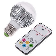 Quite a long time ago, a Chinese-made LED lamp with an IR remote control was purchased at ebay auction. The lamp has a standard E27 base, 9W power and subjectively has the brightness of a 40W incandescent lamp. From the remote you can turn on / off the lamp, as well as set 5 different levels of brightness.
The idea was the following - to assemble an alarm clock on the AVR microcontroller, which will advance in advance of the sound signal to smoothly increase the brightness of this lamp by transmitting IR commands. The lamp is screwed in instead of one of the ordinary chandeliers of the overhead lighting. Half an hour before the set time, the light turns on at the minimum brightness, then the brightness gradually increases to 100%.
')
As a result of the work, I wanted to see, if not a masterpiece, then at least something in a decent-looking body, for which it was decided to make an alarm clock in a partially glass case with touch controls. Atmel offers the QTouch library for its microcontrollers, which allows you to implement touch-sensitive buttons in your devices at minimal cost. In this project, I just wanted to try this remarkable library in practice.
The final design was as follows: a one-sided printed circuit board on which LED indicators, an IR LED, a photo sensor, a power connector are installed on the one side (front), and the rest of the elements are soldered on the other side (tracks side). Then the indicators are closed with a plate of tinted glass, on the back of which in the right places are glued touch buttons. From the back side, the board is covered with a case, which is a plastic box of a suitable size. At the same time we have an aesthetic appearance in the absence of mechanical buttons.
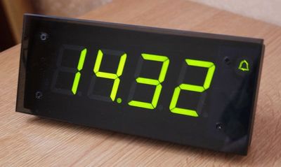
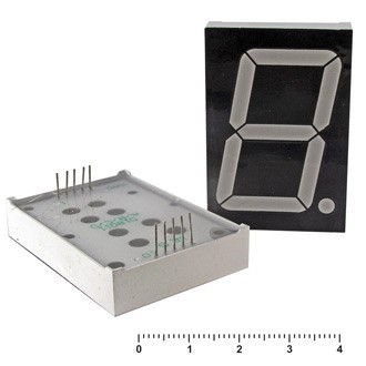
So let's get down to the design. To begin with, we will define the microcontroller - it must have a sufficient number of pins for the implementation of the display and touch buttons, and also be in a case that is not very difficult for manual soldering. ATMEGA324P satisfies these conditions (44 legs and lead pitch 0.8 mm). Choosing a display - as such, it was decided to use a LED display with large numbers (1.8 ”). The display consists of four single-digit indicators with a common anode. Typically, large-sized display segments consist of several series-connected LEDs, so a five-volt power source is indispensable, and a power source of at least 9 V is required to power the clock.
To control such a display you will need a driver. The display has a common anode, so we proceed as follows - the display cathodes through current-limiting resistors will be connected to the ULN2803 microcircuit, and for the anodes we will provide separate transistor switches. The ULN2803 chip consists of 8 transistors with resistors in the base circuit, which makes it very convenient for such an application.
Next, the actual clock, more precisely, the RTC chip. As such, the DS3231 was chosen - a chip with a built-in quartz resonator and a minimum number of external components. The manufacturer promises the accuracy of the course of a few seconds per year. Also, due to the built-in temperature meter for thermal compensation of quartz frequency drift, we get a “free” thermometer showing the temperature inside the case.
For the call, the ZP-19 piezo-emitter is used.
As an "actuator", which distinguishes an alarm clock from millions of similar ones, there is an IR LED in the circuit, which will form commands for the light bulb.
To power the clock from the mains, an unstabilized 12 V power supply is used. To power the microcontroller, a separate power supply must be provided in the circuit - we put the well-known linear power supply LM7805.
In conclusion, we will provide in the scheme a two-color LED for indicating the state of the alarm, as well as a photo sensor for realizing the change in the brightness of the indicator depending on the level of illumination. The photo sensor will be connected to the comparator, therefore, it is necessary to provide a trimming resistor to adjust the threshold.
The scheme is ready, you can start programming and manufacturing. Before manufacturing, most of the program was tested in the Proteus simulator, in which all the design was done.
Unfortunately, it was not possible to simulate the work of the QTouch library in the proteus, so it was necessary to pre-assemble part of the circuit on the breadboard and “play” with the capacitive sensors separately. The library performed well - a clear response in all cases.
The next element that required experimental testing was the remote control of the light bulb itself. Connect the photodiode to the oscilloscope and look at the signal by pressing the console buttons:

From the picture it is clear that the NEC protocol is used - one of the well-known infrared control protocols, where information is encoded by the duration of the pause between pulses. A logical 1 is a pause of 1.7 ms, a logical 0 is a pause of 0.6 ms. After the start sequence (9 ms pulse and 4.5 ms pause) 32 bits are transmitted: address, inverse address, command, inverse command. The protocol is well documented, and it is not difficult to find a detailed description on the Internet.
Using an oscilloscope, we also determine the transmission frequency - it turned out to be 38 KHz. So, the necessary codes of the remote buttons:
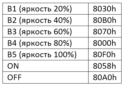
We write the functions that will form the IR commands, check with the layout - the light turns on, the brightness is adjusted - it means everything is almost ready, you can assemble the clock.
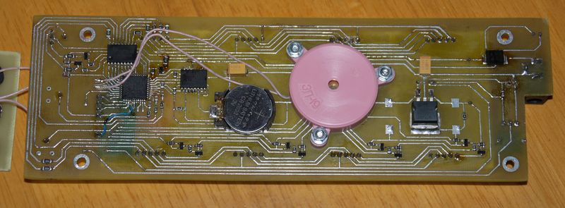
The board was made by the LUT method. I have quite a modest experience in the manufacture of boards using this method, but it turned out quite tolerant. Not without jambs - I forgot to provide the RESET pin in the programming connector on the circuit, I had to solder it separately. In the photo just collected fee, with flux still not washed in places.
Once again, we check, turn on, upload the firmware and start the debugging process. After everything works, you can close everything in the case.
We continue to catch mistakes. As already mentioned, it was decided to order a plate made of tinted glass with a finished edge and four holes as the main body element, through which it will be attached to the board. If someone wants to make a similar design - I advise you to design the board after ordering the plate. I found a company that promised any work with glass according to sketches, with high precision, modern machine tools, etc., in practice, the mounting holes were drilled with a centimeter difference from the sketch. However, I didn’t make any claims, I just adjusted the fee a little. Another mistake was the wrong choice of the diameter of the holes in the glass - initially for fixing I wanted to use decorative nuts with a flat surface. These were found on ebay in the store accessories for metalworkers - used, apparently, to simulate the rivets on the belts (the so-called Chicago Screws ). However, when the nuts arrived, it turned out that they had a threaded part diameter of 5 mm, and the holes in the glass plate were 4 mm, so the idea had to be abandoned and the glass was fixed with ordinary countersunk bolts, which were then simply painted with a marker.
On the reverse side of the glass are touch sensors - for this we use aluminum tape. To the sensors, pieces of foamed polyethylene (from packages with ebay) are pressed against the wires from the board. There is an indicator LED under the alarm button - the logic of its operation is as follows: if the alarm rings in the next 24 hours - green, will not ring - red, all alarms are off - the LED does not light up. The alarm clock symbol (bell) is also translated into Scotch tape using the LUT method, carefully cut it out and glue it to the glass.
Tinted glass has shown itself to be excellent in working with touch buttons and aesthetic design of the display, but it very significantly attenuates IR radiation. One IR-LED works uncertainly, so that in addition to the gap in the track, another was additionally soldered, which shines into the hole in the upper wall of the housing. As a result, we have a confident operation, no worse than the regular remote.
According to the results of the operation of the alarm clock, it can be said that the idea has fully justified itself - it is indeed much easier to wake up with such a device on a dark winter morning. Additionally, we have a bedside remote lighting switch.
The article was written more out of a desire to share the idea of how to implement this with minimal effort, but if someone wants to repeat the device in this form, it’s ready to provide the firmware and answer questions.
Update:
Link to the firmware sources, circuit and board in Proteus format:
clock.zip
List of sources:
Source: https://habr.com/ru/post/248289/
All Articles