A short course in computer graphics: we write a simplified OpenGL do it yourself, article 2 of 6
Course content
- Article 1: Bresenham algorithm
- Article 2: rasterization of the triangle + clipping of the rear faces
- Article 3: Removing invisible surfaces: z-buffer
- Article 4: Required Geometry: Matrix Festival
- Article 5: We write shaders for our library
- Article 6: A little more than just a shader: shadow rendering
Code enhancement
The official translation (with a bit of polishing) is available here.
Update:
Attention, Article 4c provides a new, simpler version of the rasterizer.
')
Let's get acquainted, it's me.
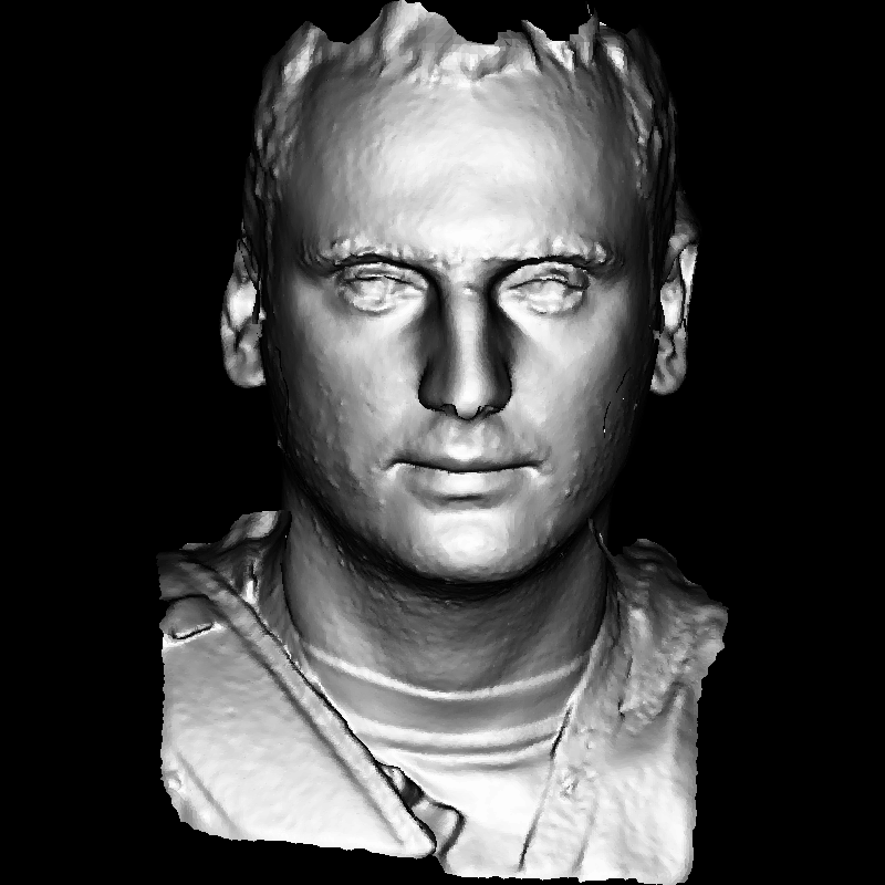
That is, the model of my head, rendered in the program, which we will do in the next hour or two.
Last time we drew a wire mesh of a three-dimensional model, this time we fill in polygons. More precisely, the triangles, since OpenGL almost every polygon triangulates, so there’s no need to disassemble the complex case. I remind you that this series of articles was created for independent programming. The time I give here is not the time to read my code. This is the time to write your code from scratch. My code is here only to compare your (working) code with mine. I’m not a good programmer at all, so your code can be significantly better than mine. Any criticism is welcome, any questions glad.
Please, if you follow this tutorial and write your code, post it on github.com/code.google.com and the like and give links in the comments! It may well help both you (other people may advise something) and future readers.
Draw a filled triangle
So, the topic for today (about two hours for badly programming, but motivated students): drawing two-dimensional triangles. Last time we disassembled the Brezenham algorithm for rasterization of the segment, now the task is to draw a filled triangle. You will laugh, but this is not a trivial task. I don't know why, but I know that it is. Most of my students, without prompts, spend significantly more than a couple of hours on this task. Let's determine the method, and then we will program.
At the very beginning, let's consider this pseudocode:
 triangle (vec2 points [3]) {
     vec2 bbox [2] = find_bounding_box (points);
     for (each pixel in the bounding box) {
         if (inside (points, pixel)) {
             put_pixel (pixel);
         }
     }
 }
I really love this method. He is simple and working. It is extremely easy to find a descriptive rectangle; it’s also easy to verify that a point belongs to a two-dimensional triangle (and any convex polygon).
Offtopic: if I need to write a code that will spin on, say, a plane, and this code will have to check the belonging of a point to a polygon, I will never sit on this plane. This is a surprisingly difficult problem if we want to solve it reliably .
Why do I love this code? Yes, because, having seen such a thing, a newcomer to programming will be enthusiastically perceived by him, a person who is a little familiar with programming, just smirks smugly, saying that the idiot wrote. An expert in computer graphics programming just shrugs, saying, well, yes, that’s how it works in real life. Massively parallel computing in thousands of small GPUs (I’m talking about ordinary consumer computers) work wonders. But we will write code for the central processor, so we will not use this method. And what's the difference, as it is there in silicon, our abstraction is enough to understand the principle of operation.
Ok, the initial stub will look like this:
 void triangle (Vec2i t0, Vec2i t1, Vec2i t2, TGAImage & image, TGAColor color) {
     line (t0, t1, image, color);
     line (t1, t2, image, color);
     line (t2, t0, image, color);
 }

 [...]

     Vec2i t0 [3] = {Vec2i (10, 70), Vec2i (50, 160), Vec2i (70, 80)};
     Vec2i t1 [3] = {Vec2i (180, 50), Vec2i (150, 1), Vec2i (70, 180)};
     Vec2i t2 [3] = {Vec2i (180, 150), Vec2i (120, 160), Vec2i (130, 180)};


     triangle (t0 [0], t0 [1], t0 [2], image, red);
     triangle (t1 [0], t1 [1], t1 [2], image, white);
     triangle (t2 [0], t2 [1], t2 [2], image, green);

As usual, a code fingerprint is available on the githaba. Everything is simple in this code: I give three triangles for initial debugging of your code; if inside the triangle function just make the call line (), then we get the outline of the triangle. How to draw a filled triangle?
A good method for drawing a triangle should have the following properties:
- It should be (surprise) simple and fast.
- It should be symmetrical: the picture should not depend on the order of the vertices passed to the drawing function
- If two triangles have two common vertices, there should be no holes between them due to rounding rasterization.
There are many more requirements to add, but we are content with these three.
Traditionally, line sweeping is used:
- Sort the vertices of the triangle by their y-coordinate
- Rasterize parallel the left and right borders of the triangle
- Draw a horizontal segment between the left and right point of the border
Then my students begin to get lost, who is left, who is right, and indeed, there are three segments in the triangle ...
At this point, I leave my students for about an hour, reading my code is far less valuable than comparing my (suffered!) Code with mine.
[An hour has passed]
How do i draw? Once again, if you have a better method, I will use it with great pleasure. Let's assume that we have three points of the triangle, t0, t1, t2, they are sorted in ascending order of the y-coordinate.
Then the border A will be between t0 and t2, the border B will be between t0 and t1, and then between t1 and t2.
 void triangle (Vec2i t0, Vec2i t1, Vec2i t2, TGAImage & image, TGAColor color) {
     // sort the vertices, t0, t1, t2 lower-to-upper (bubblesort yay!)
     if (t0.y> t1.y) std :: swap (t0, t1);
     if (t0.y> t2.y) std :: swap (t0, t2);
     if (t1.y> t2.y) std :: swap (t1, t2);

     line (t0, t1, image, green);
     line (t1, t2, image, green);
     line (t2, t0, image, red);
 }
Here we have border A drawn in red, and border B in green.

Border B, unfortunately, is compound. Let's draw the lower half of the triangle, cutting it horizontally at the breakpoint of the border B.
 void triangle (Vec2i t0, Vec2i t1, Vec2i t2, TGAImage & image, TGAColor color) {
     // sort the vertices, t0, t1, t2 lower-to-upper (bubblesort yay!)
     if (t0.y> t1.y) std :: swap (t0, t1);
     if (t0.y> t2.y) std :: swap (t0, t2);
     if (t1.y> t2.y) std :: swap (t1, t2);

     int total_height = t2.y-t0.y;
     for (int y = t0.y; y <= t1.y; y ++) {
         int segment_height = t1.y-t0.y + 1;
         float alpha = (float) (y-t0.y) / total_height;
         float beta = (float) (y-t0.y) / segment_height;  // be careful with divisions by zero
         Vec2i A = t0 + (t2-t0) * alpha;
         Vec2i B = t0 + (t1-t0) * beta;
         image.set (Ax, y, red);
         image.set (Bx, y, green);
     }
 }

Notice that this time I have got discontinuous segments. Unlike the last time (where we drew straight lines), I didn’t get fooled by rotating the image 90 °. Why? This turns out not to be an obvious point. Simply, if we connect the corresponding pairs of dots with horizontal lines, the spaces will disappear:

Now it remains to draw the second half of the triangle. This can be done by adding a second cycle:
 void triangle (Vec2i t0, Vec2i t1, Vec2i t2, TGAImage & image, TGAColor color) {
     // sort the vertices, t0, t1, t2 lower-to-upper (bubblesort yay!)
     if (t0.y> t1.y) std :: swap (t0, t1);
     if (t0.y> t2.y) std :: swap (t0, t2);
     if (t1.y> t2.y) std :: swap (t1, t2);

     int total_height = t2.y-t0.y;
     for (int y = t0.y; y <= t1.y; y ++) {
         int segment_height = t1.y-t0.y + 1;
         float alpha = (float) (y-t0.y) / total_height;
         float beta = (float) (y-t0.y) / segment_height;  // be careful with divisions by zero
         Vec2i A = t0 + (t2-t0) * alpha;
         Vec2i B = t0 + (t1-t0) * beta;
         if (Ax> Bx) std :: swap (A, B);
         for (int j = Ax; j <= Bx; j ++) {
             image.set (j, y, color);  // attention, due to int casts t0.y + i! = Ay
         }
     }
     for (int y = t1.y; y <= t2.y; y ++) {
         int segment_height = t2.y-t1.y + 1;
         float alpha = (float) (y-t0.y) / total_height;
         float beta = (float) (y-t1.y) / segment_height;  // be careful with divisions by zero
         Vec2i A = t0 + (t2-t0) * alpha;
         Vec2i B = t1 + (t2-t1) * beta;
         if (Ax> Bx) std :: swap (A, B);
         for (int j = Ax; j <= Bx; j ++) {
             image.set (j, y, color);  // attention, due to int casts t0.y + i! = Ay
         }
     }
 }

One could calm down on this, but indigestion happens to me when I see the same code twice, and even so near. Therefore, we will make it a little less readable, but more simple for modifications.
void triangle (Vec2i t0, Vec2i t1, Vec2i t2, TGAImage & image, TGAColor color) {if (t0.y == t1.y && t0.y == t2.y) return; // i dont care about degenerate triangles // sort the vertices t0, t1, t2 lower-to-upper (bubblesort yay!) if (t0.y> t1.y) std :: swap (t0, t1); if (t0.y> t2.y) std :: swap (t0, t2); if (t1.y> t2.y) std :: swap (t1, t2); int total_height = t2.y-t0.y; for (int i = 0; i <total_height; i ++) {bool second_half = i> t1.y-t0.y || t1.y == t0.y; int segment_height = second_half? t2.y-t1.y: t1.y-t0.y; float alpha = (float) i / total_height; float beta = (float) (i- (second_half? t1.y-t0.y: 0)) / segment_height; // be careful here A = t0 + (t2-t0) * alpha; Vec2i B = second_half? t1 + (t2-t1) * beta: t0 + (t1-t0) * beta; if (Ax> Bx) std :: swap (A, B); for (int j = Ax; j <= Bx; j ++) {image.set (j, t0.y + i, color); // attention, due to int casts t0.y + i! = Ay}}} Fingerprint code for drawing 2d triangles.
Draw a model
We can already draw a model with empty triangles, let's fill them with a random color, this will help us check how well we have encoded the filling of triangles. Here is the code .
     for (int i = 0; i <model-> nfaces (); i ++) {
         std :: vector <int> face = model-> face (i);
         Vec2i screen_coords [3];
         for (int j = 0; j <3; j ++) {
             Vec3f world_coords = model-> vert (face [j]);
             screen_coords [j] = Vec2i ((world_coords.x + 1.) * width / 2., (world_coords.y + 1.) * height / 2.);
         }
         triangle (screen_coords [0], screen_coords [1], screen_coords [2], image, TGAColor (rand ()% 255, rand ()% 255, rand ()% 255, 255));
     }
It's simple: as before, we run through all the triangles, turn the world coordinates into screen coordinates and draw triangles. A detailed description of the different coordinate systems in subsequent articles. You should get something like this:

Flat toning
Let's now remove these clown colors and illuminate our model.
Captain Obvious: "With the same intensity of light, the polygon is lit as brightly as possible if the light is perpendicular to it."
Let's compare:


Zero illumination we get if the polygon is parallel to the vector of light.
To paraphrase: the intensity of illumination is equal to the scalar product of the vector of light and the normal to this triangle.
The normal to a triangle can be calculated simply as the vector product of its two edges.
     for (int i = 0; i <model-> nfaces (); i ++) {
         std :: vector <int> face = model-> face (i);
         Vec2i screen_coords [3];
         Vec3f world_coords [3];
         for (int j = 0; j <3; j ++) {
             Vec3f v = model-> vert (face [j]);
             screen_coords [j] = Vec2i ((v.x + 1.) * width / 2., (v.y + 1.) * height / 2.);
             world_coords [j] = v;
         }
         Vec3f n = (world_coords [2] -world_coords [0]) ^ (world_coords [1] -world_coords [0]);
         n.normalize ();
         float intensity = n * light_dir;
         if (intensity> 0) {
             triangle (screen_coords [0], screen_coords [1], screen_coords [2], image, TGAColor (intensity * 255, intensity * 255, intensity * 255, 255));
         }
     }
But the scalar product can be negative, what does it mean? This means that the light falls behind the polygon. If the model is good (usually not our concern, but 3d modelers), then we just can not draw this triangle. This allows you to quickly remove some of the invisible triangles. In English literature, called back-face culling .

Does my head model look more detailed? Well, in it a quarter of a million triangles. Nothing, we will add the details later, after receiving the picture that I gave for the seed in the first article.
Notice, the internal cavity of the mouth is drawn over the lips. Well, what, such a quick clipping of invisible triangles removes all unnecessary only for convex models. We will remove these flaws next time by encoding the z-buffer.
The current version of the renderer.
Source: https://habr.com/ru/post/248159/
All Articles