The sound on the chip AY-3-8910 (or Yamaha YM2149F) comes from the ZX Spectrum on the PC via USB
About a year has passed since the successful connection of the YM2149F music synthesizer to the LPT port of the computer . LPT is nice, but time does not stand still, and finding a computer or laptop with an LPT port is becoming more and more difficult. Yes, and the author himself (that is, I) got tired of climbing every time under the table where the sistemnik is standing, and poking the LPT board onto something else, for example, a programmer (I have a Willem LPT programmer, but not the point). Therefore, this time we will connect the YM2149F chip to USB. And of course, to meet the requirements of the era, we will do it on a penny old PIC16F628 microcontroller.
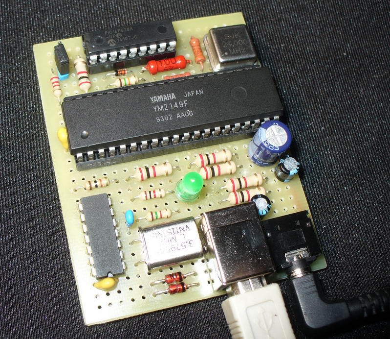
In short, YM2149F (or its functional analogue AY-3-8910 ) is a three-part audio synthesizer chip, used in old computers like Atari ST, Amstrad CPC, ZX Spectrum, MSX and some others for playing music. In Russia, the chip has gained a certain fame due to the installation in various clones of the ZX Spectrum. During the procession of the ZX Spectrum in the former USSR, musicians have written thousands of melodies for this sound programmable generator. And now you can completely find people who create music for this chip. At the end of the article there will be links to a huge archive of chip tyuns for YM / AY for hundreds of hours of continuous listening.
Like last time, before the start, I immediately give a link to listen to the final result: https://soundcloud.com/tronix286 The latest entries were made just from this device. I recorded it as a player that writes a maximum of 128Kb / s MP3, so in reality the device sounds “brighter”. But you can get a general idea of the sound.
')
Why such a weird choice of controller? Why not AVR / ARM / iCore i7 / FTDI at the worst? Partially the answer to this question is given at the beginning of the topic: retro synthesizer - retro microcontroller! Moreover, AY-3-8910 and Microchip, one may say, have common roots. In general, it was a series of strange circumstances. Firstly, I stumbled across the Internet on a library that implements a software (software) USB 1.1 stack for PIC16F628 microcontrollers — this is the library: 16FUSB . Secondly, I had a couple of PIC16F628A lying and gathering dust for a long time, which I did not know where to go. Thirdly, on the computer there was already configured software (MPLABX, MPASM) and there is a programmer for the PIC. Well, unlike the V-USB software stack on the AVR, known to many, there are few or even no projects on PICs without hardware USB. And this means that historical injustice must be restored.
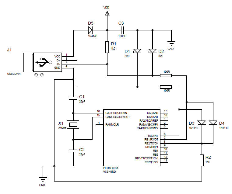
Here is a typical wiring diagram from the 16fusb library site:
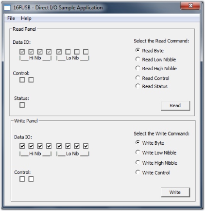
Included with the 16fusb library is a good example called “direct-io”. The meaning is simple - send via USB bytes and it is “displayed” on the eight legs of the microcontroller. You can also send an additional two control signals, that is, two more bits (or two legs). And in the opposite direction, that is, from the controller to the host (computer).
The YM2149F is controlled using an eight-bit data bus D0-D7 and three control signals BC1, BDIR and RESET. BC1 and BDIR control the selection of the register address and its value, as well as transfer the microchip to the inactive state. The RESET signal is used to reset all registers to the original value. Thus, reading from the PIC to the computer is not necessary; only need the ability to send commands to YM. And we need another third control signal, which means another MK leg.
The following was done in its firmware for controlling the YM2149F specifically:
As mentioned above, there is a need for another control signal - RESET, and there are no free legs anymore. Therefore, a quartz oscillator is used for clocking the PIC, and not a quartz, thereby releasing one leg of the MK (RA6) necessary to control the RESET signal. The RA5 leg sticking in the air in this family only works as an input and cannot be used to control the output signal. It would be possible to shift the functionality of catching the end of the USB package (EOP) from the RB2 leg, but this is not so simple - unlike the RB2 leg, the RA5 leg shares the functionality with MCLR and VPP for programming and the input is organized as a Schmitt trigger. He just does not have enough voltage after the diodes to work. On the other hand, for clocking the YM2149F assembled generator on the 74HC02 chip and 3.579545 MHz quartz. It would be possible to try to use the second free half of the chip for assembling a similar generator and for the PIC, but two things stopped: 1) I don’t have 24 MHz quartz (and there was a quartz oscillator from some ancient mother) 2) I don’t know how 74HC02 will behave if it has different frequencies from “different sides”, and one of them is quite high (24 MHz is still a very large frequency). Another option is how to free the RA6 leg for quartz: Signals BC1 and BDIR accept only such values:
And never BC1 = 1, BDIR = 0. This can be used as a RESET by adding the NOT and NOR logic from the half of the 74HC02 chip and inverting the output signal using a transistor. Of course, to issue BC = 1 and BDIR = 0 you need to tweak the firmware a little.
And yet, the leg of RA4, which controls the BDIR signal, is open-collector, so you definitely need to pull it up to power - in the diagram it is a 10K resistor R5.
On the computer side, as the music player, an excellent cross-platform player chip tunes ZX Tune :
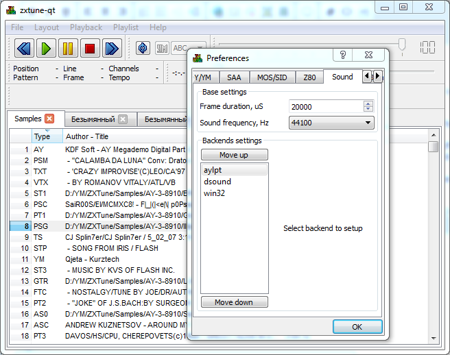
It does not directly support USB, but if it finds one of the dlportio.dll / inpout32.dll / inpoutx64.dll libraries in its directory, it allows it to switch to the YM-LPT audio output settings ( for the past project ), and then use the __stdcall function void DlPortWritePortUchar (unsigned short port, unsigned char val); for issuing bytes YM2149. Port 0x378 data, Port 0x37a transmission of control signals (D1 - ~ BDIR, D2 - BC1, D3 - ~ RESET). Thus, it is possible to write a small stub library with a single DlPortWritePortUchar function in which to redirect the byte output to a USB device, which was done. I just took the source code of the inpout32 library as a basis and wrote a stub function to redirect the output of bytes to this device. As a result, it is enough to put this stub library inpout32.dll or inpoutx64.dll , depending on the player version used (x86 / x64), in the same directory as the ZX Tune player, run it and in the sound settings move the aylpt device to the top ( as in the screenshot above).
Drivers for Win XP, Win 7 (x32 / x64) can be downloaded here: 16FUSB_driver-libusb-win32-1.2.6.0.zip
Device layout: ym-usb_scheme_1.0.rar
Compiled firmware (.hex) and compiled DLL stubs: ym-usb_firmware_and_DLLs_v1.2.rar
Source codes of the firmware: ym-usb_PIC16F628A_source_v1.2.rar
Source code of the stub library: inpout32-64_DLL_source_v1.2.rar
General Instruments AY-3-8910 / 8912 Programmable Sound Generator (PSG) data Manual: http://bulba.untergrund.net/AY-3-8910.rar
The topic on the forum ZX.PK.ru, from which the device was "born": http://zx-pk.ru/showthread.php?t=22202
Huge archive of tracker music: Modland ( FTP )
ZX music online: http://zxtunes.com/
All good!
In short, YM2149F (or its functional analogue AY-3-8910 ) is a three-part audio synthesizer chip, used in old computers like Atari ST, Amstrad CPC, ZX Spectrum, MSX and some others for playing music. In Russia, the chip has gained a certain fame due to the installation in various clones of the ZX Spectrum. During the procession of the ZX Spectrum in the former USSR, musicians have written thousands of melodies for this sound programmable generator. And now you can completely find people who create music for this chip. At the end of the article there will be links to a huge archive of chip tyuns for YM / AY for hundreds of hours of continuous listening.
Demo
Like last time, before the start, I immediately give a link to listen to the final result: https://soundcloud.com/tronix286 The latest entries were made just from this device. I recorded it as a player that writes a maximum of 128Kb / s MP3, so in reality the device sounds “brighter”. But you can get a general idea of the sound.
')
Iron
Why such a weird choice of controller? Why not AVR / ARM / iCore i7 / FTDI at the worst? Partially the answer to this question is given at the beginning of the topic: retro synthesizer - retro microcontroller! Moreover, AY-3-8910 and Microchip, one may say, have common roots. In general, it was a series of strange circumstances. Firstly, I stumbled across the Internet on a library that implements a software (software) USB 1.1 stack for PIC16F628 microcontrollers — this is the library: 16FUSB . Secondly, I had a couple of PIC16F628A lying and gathering dust for a long time, which I did not know where to go. Thirdly, on the computer there was already configured software (MPLABX, MPASM) and there is a programmer for the PIC. Well, unlike the V-USB software stack on the AVR, known to many, there are few or even no projects on PICs without hardware USB. And this means that historical injustice must be restored.
Here is a typical wiring diagram from the 16fusb library site:
Included with the 16fusb library is a good example called “direct-io”. The meaning is simple - send via USB bytes and it is “displayed” on the eight legs of the microcontroller. You can also send an additional two control signals, that is, two more bits (or two legs). And in the opposite direction, that is, from the controller to the host (computer).
The YM2149F is controlled using an eight-bit data bus D0-D7 and three control signals BC1, BDIR and RESET. BC1 and BDIR control the selection of the register address and its value, as well as transfer the microchip to the inactive state. The RESET signal is used to reset all registers to the original value. Thus, reading from the PIC to the computer is not necessary; only need the ability to send commands to YM. And we need another third control signal, which means another MK leg.
The following was done in its firmware for controlling the YM2149F specifically:
- everything related to the reading of signals from the PIC to the host (computer) has been thrown out to increase the processing speed of USB requests;
- The state of the directions of the I / O ports is rigidly specified during the initialization of the MK and does not change in the procedures for issuing a byte to its feet.
- 64 byte circular buffer is organized. When decoding a request from a host, the bytes are added to the buffer. When there is free time, data from the buffer is output to YM.
- optimized speed of issuing bytes per foot MK. Partly due to the strictly specified I / O directions, partly due to the prominence of the previous state of the control bits.
- Fixed a bug with PIC looping through several thousand packets (deployed the RxLoop loop in the isr.asm file, instead of goto RxLoop, a check for the end of the packet is inserted)
- something else I don't remember
As mentioned above, there is a need for another control signal - RESET, and there are no free legs anymore. Therefore, a quartz oscillator is used for clocking the PIC, and not a quartz, thereby releasing one leg of the MK (RA6) necessary to control the RESET signal. The RA5 leg sticking in the air in this family only works as an input and cannot be used to control the output signal. It would be possible to shift the functionality of catching the end of the USB package (EOP) from the RB2 leg, but this is not so simple - unlike the RB2 leg, the RA5 leg shares the functionality with MCLR and VPP for programming and the input is organized as a Schmitt trigger. He just does not have enough voltage after the diodes to work. On the other hand, for clocking the YM2149F assembled generator on the 74HC02 chip and 3.579545 MHz quartz. It would be possible to try to use the second free half of the chip for assembling a similar generator and for the PIC, but two things stopped: 1) I don’t have 24 MHz quartz (and there was a quartz oscillator from some ancient mother) 2) I don’t know how 74HC02 will behave if it has different frequencies from “different sides”, and one of them is quite high (24 MHz is still a very large frequency). Another option is how to free the RA6 leg for quartz: Signals BC1 and BDIR accept only such values:
BC1 BDIR 0 0 0 1 1 1 And never BC1 = 1, BDIR = 0. This can be used as a RESET by adding the NOT and NOR logic from the half of the 74HC02 chip and inverting the output signal using a transistor. Of course, to issue BC = 1 and BDIR = 0 you need to tweak the firmware a little.
And yet, the leg of RA4, which controls the BDIR signal, is open-collector, so you definitely need to pull it up to power - in the diagram it is a 10K resistor R5.
Soft
On the computer side, as the music player, an excellent cross-platform player chip tunes ZX Tune :
It does not directly support USB, but if it finds one of the dlportio.dll / inpout32.dll / inpoutx64.dll libraries in its directory, it allows it to switch to the YM-LPT audio output settings ( for the past project ), and then use the __stdcall function void DlPortWritePortUchar (unsigned short port, unsigned char val); for issuing bytes YM2149. Port 0x378 data, Port 0x37a transmission of control signals (D1 - ~ BDIR, D2 - BC1, D3 - ~ RESET). Thus, it is possible to write a small stub library with a single DlPortWritePortUchar function in which to redirect the byte output to a USB device, which was done. I just took the source code of the inpout32 library as a basis and wrote a stub function to redirect the output of bytes to this device. As a result, it is enough to put this stub library inpout32.dll or inpoutx64.dll , depending on the player version used (x86 / x64), in the same directory as the ZX Tune player, run it and in the sound settings move the aylpt device to the top ( as in the screenshot above).
Download for free and without SMS
Drivers for Win XP, Win 7 (x32 / x64) can be downloaded here: 16FUSB_driver-libusb-win32-1.2.6.0.zip
Device layout: ym-usb_scheme_1.0.rar
Compiled firmware (.hex) and compiled DLL stubs: ym-usb_firmware_and_DLLs_v1.2.rar
Source codes of the firmware: ym-usb_PIC16F628A_source_v1.2.rar
Source code of the stub library: inpout32-64_DLL_source_v1.2.rar
General Instruments AY-3-8910 / 8912 Programmable Sound Generator (PSG) data Manual: http://bulba.untergrund.net/AY-3-8910.rar
The topic on the forum ZX.PK.ru, from which the device was "born": http://zx-pk.ru/showthread.php?t=22202
Huge archive of tracker music: Modland ( FTP )
ZX music online: http://zxtunes.com/
All good!
Source: https://habr.com/ru/post/248115/
All Articles