Manual installation of complex boards on components 0402, 0603, QFN, LQFP and THT
Greetings

Today we will talk about how to achieve high quality installation on boards with a large number of components - up to 1500pcs (more can be done with tight installation or 1-2 boards being assembled at the same time - no more). The need for such a complex installation usually arises in the manufacture of the first layout or several samples to ensure the correctness of the trace of the printed circuit board (the main difficult moments) or during one-time production. After receiving such a layout, you can begin to debug the software and make adjustments to the board. The factory assembly, in this case, does not quite fit because of its cost, the preparation of design documentation, selection of components, deadlines, prototyping and much more (under the cut of an 8Mb image).
')
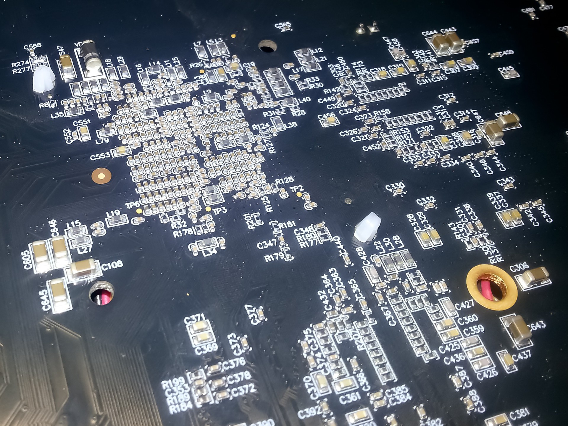
Fig. 1. Finished printed circuit board with components 0402 (reverse side).
So let's start by defining what we need. All surface mounting will be done with a hairdryer and solder paste, as this is many times faster and more qualitatively than with a soldering iron and solder in a wire.
1. Soldering station (for example, Lukey 852D + with nozzle 10mm).
2. Thin non-magnetic tweezers (for installing components).
3. Tweezers with a wide grip (for applying solder paste).
4. Flux (for example, Amtech NC-559-ASM, or another washout free).
5. Solder paste (Solder paste W001).
6. Good light and table.
7. Brush / bath / alcohol for washing the circuit board.
In the process, it will become clear what is what, so we will not focus here. To begin, let's make all the preparations and understand the soldering technology. In order to solder the two surfaces, they must first be tinned, then leaned against each other, heated and after the tin has completely melted - cooled. This is in brief. High-quality soldering has no inclusions, cracks, cracks and has a uniform structure. Cooling of the solder should occur in a stationary state, only in this case it will harden correctly.
Solder paste needs a little refinement. In order for it to overlap well and spread out evenly, it must be diluted with flux in a ratio of approximately 2: 1 (mix well into a homogeneous mass). In some cases, the proportion may vary, for example, if all contact pads have a large area, then the solder should be somewhat thicker and vice versa.
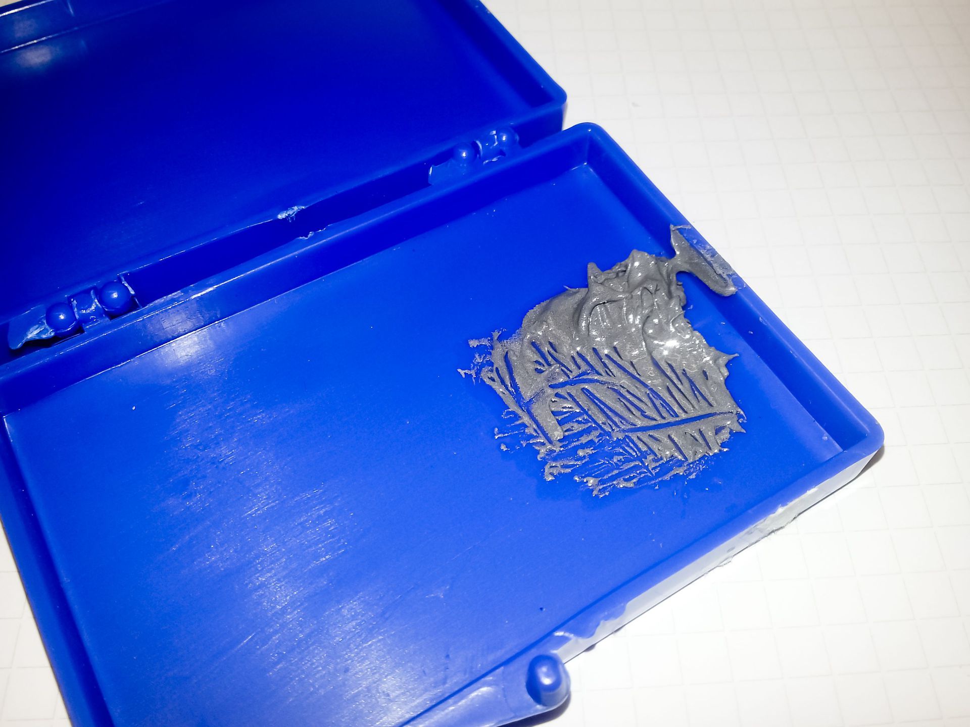
Fig. 2. Solder paste.
In order to step by step explain the entire installation process we solder a part of a small board on which various components are located. The first thing that needs to be done (if the board is only from production and clean) is to apply solder to it. The easiest and fastest, with a certain skill, is a method of applying wide tweezers (or a spatula). Below are the slides of the soldering process. At one time it is necessary to take a small amount of solder and apply it neatly and thinly to the board (as with a spatula). There is no need to put it exclusively on the contact pads, in the process of warming up, because of the large amount of flux, the excess tin will go to the contact pads or turn into balls that need to be transferred to the contact pads manually (later it will be described how to do it).
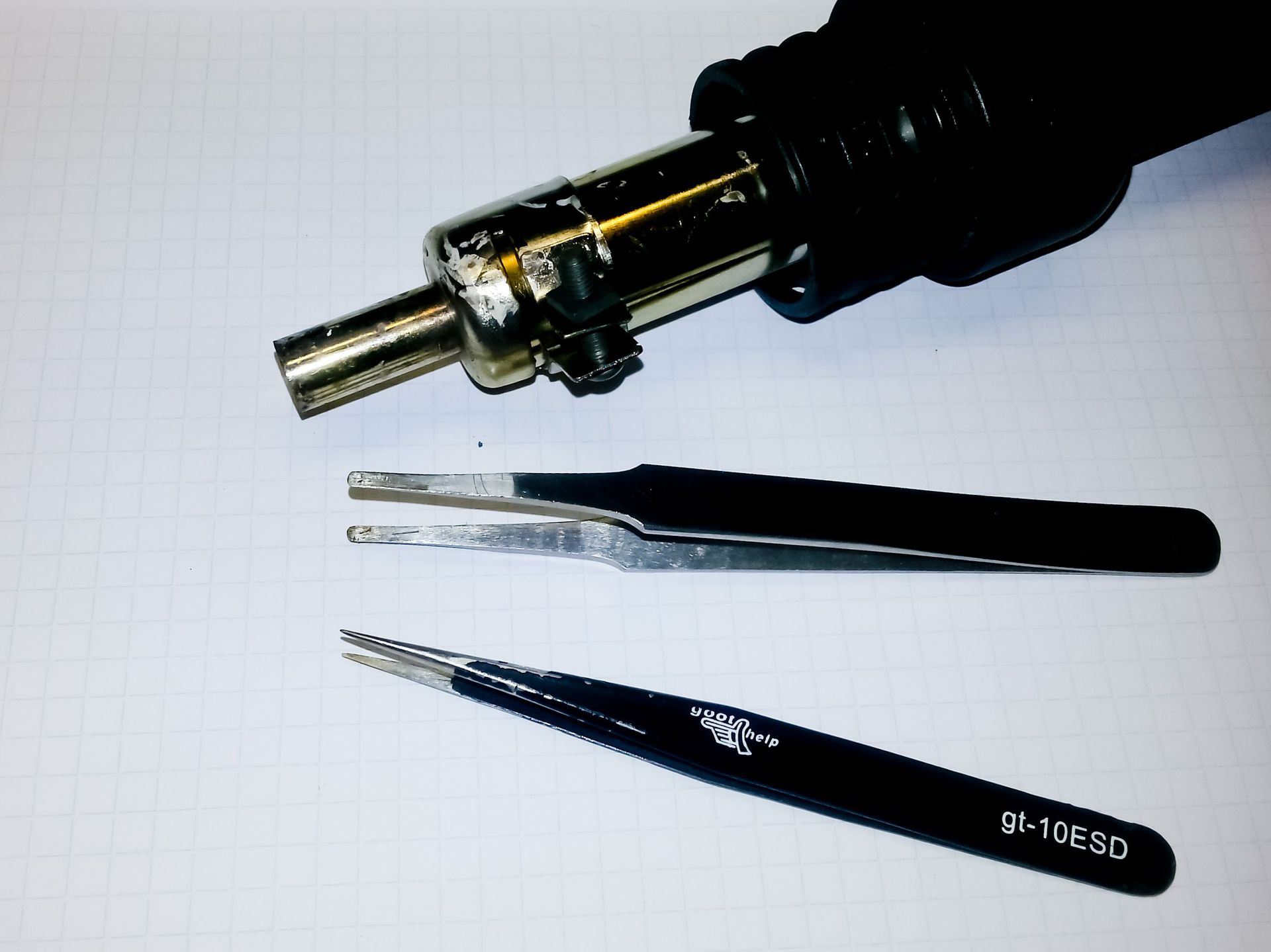

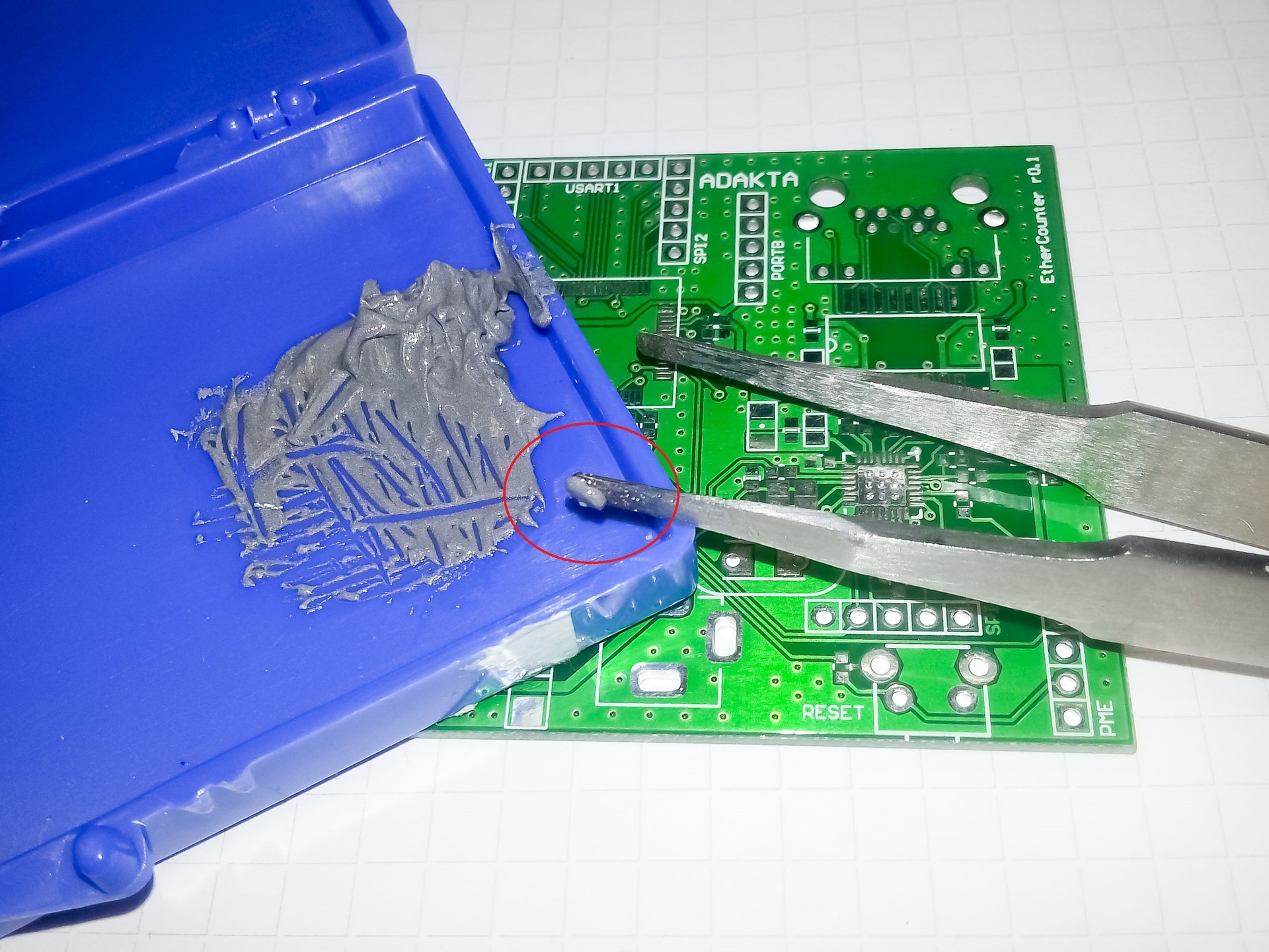
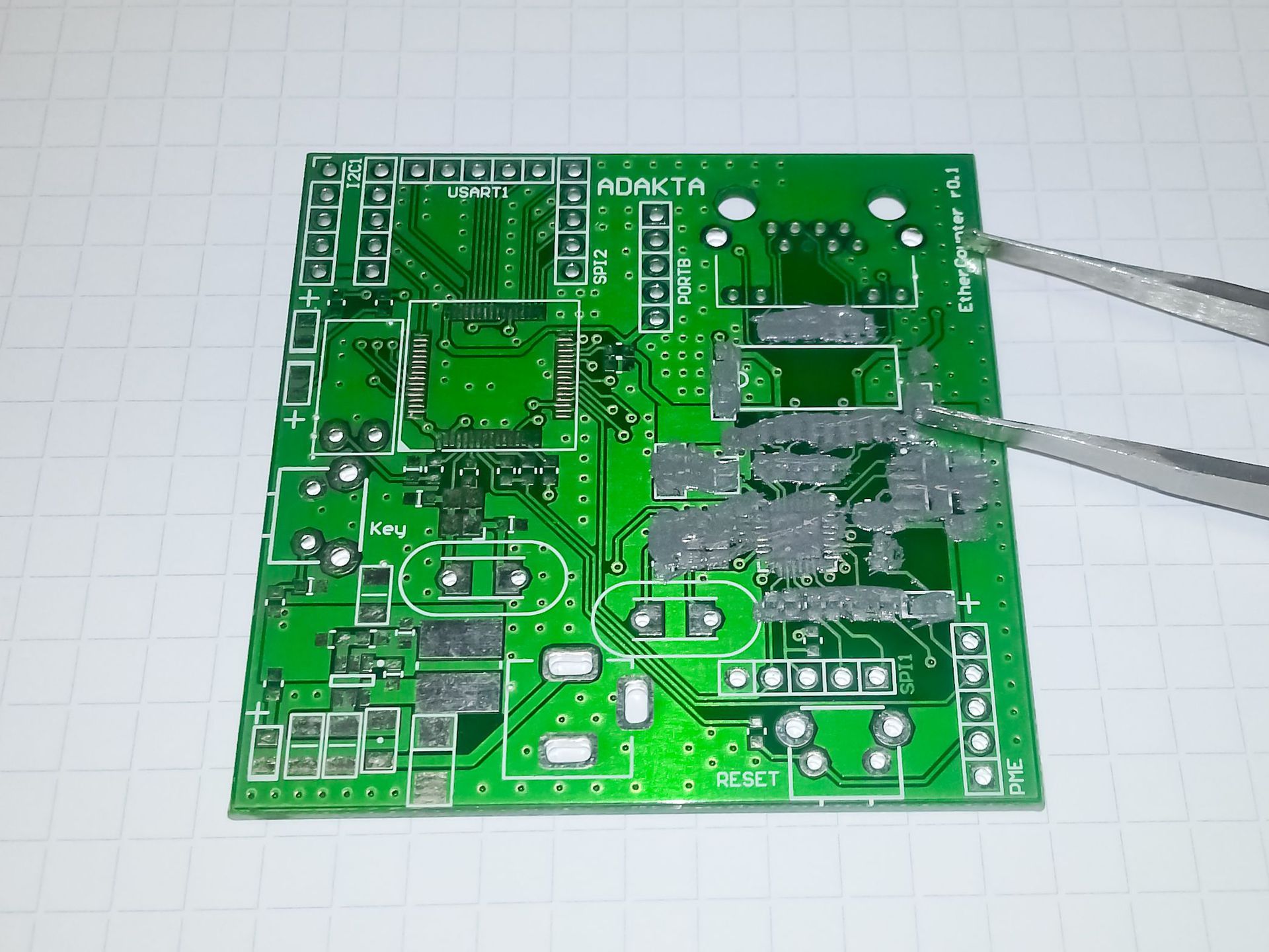
Fig. 3. The process of applying solder to the board.
Arrangement of components. Not all components can be placed immediately after applying the solder paste. For example, elements in LQFP packages with a lead pitch of less than 0.8 mm should be installed a little later - after the first warm-up with a hair dryer, otherwise there will be short circuits between the leads that will be difficult to remove (of course, you can use a “braid”, but try do without it). So, first we install SMD capacitors, resistors, diodes, etc., components in QFN packages. For this we need a thin non-magnetic tweezers. For quick and easy search for components, I use the search in Altium Designer (the project, respectively, was made there). The search for components is performed from left to right, top to bottom, select a component, for example, a capacitor 100n, find them all and install them on the board.
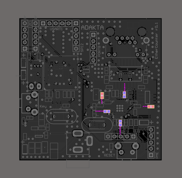
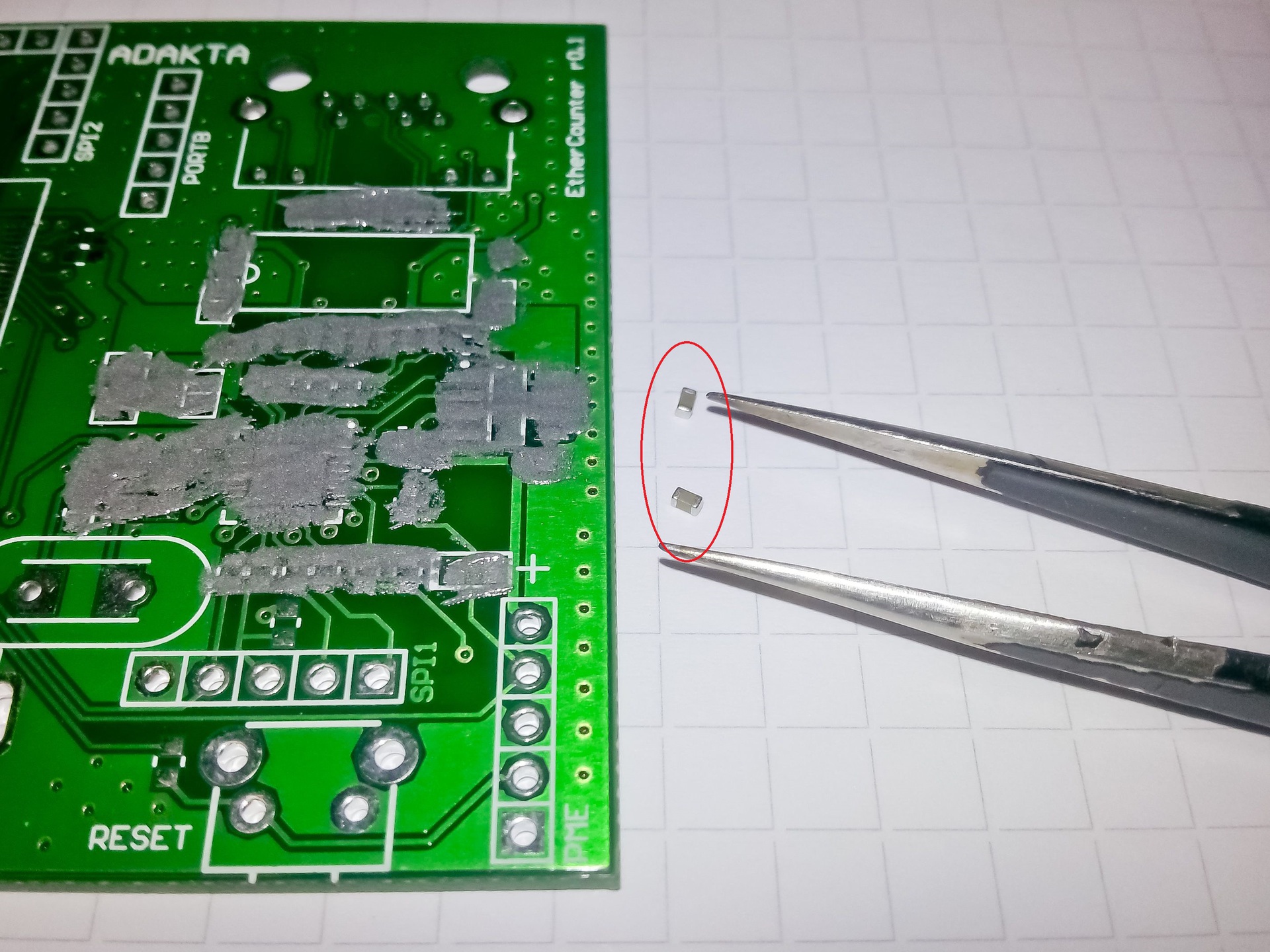
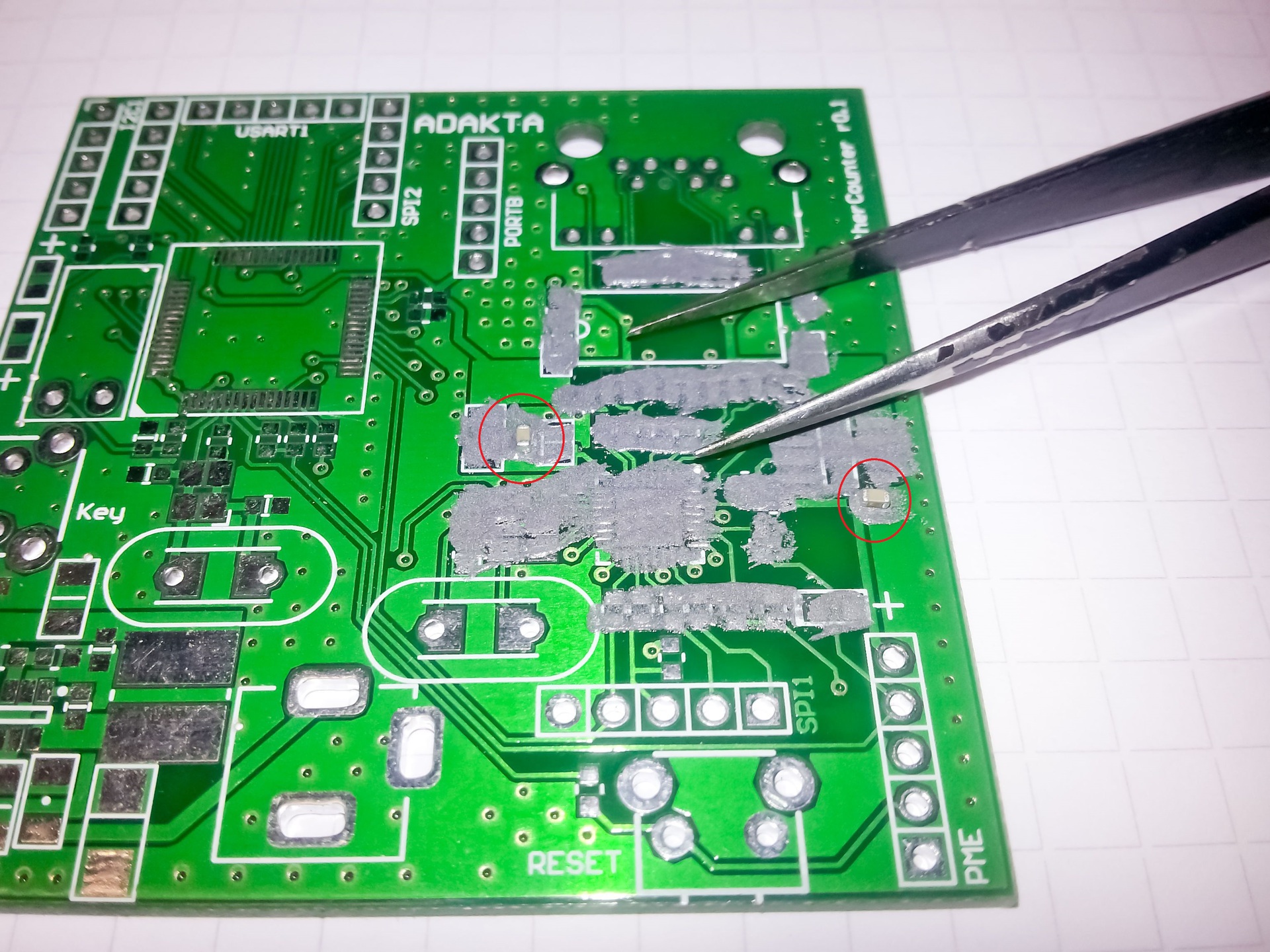
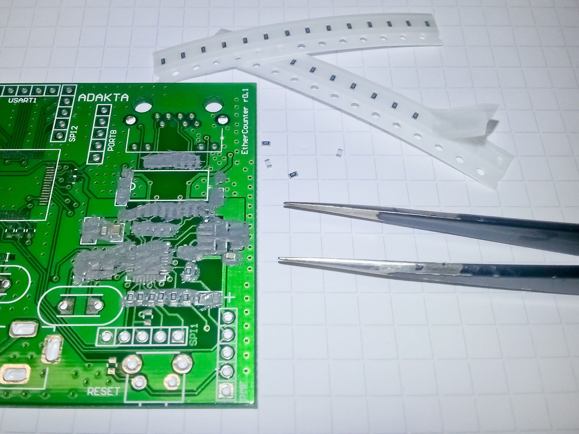
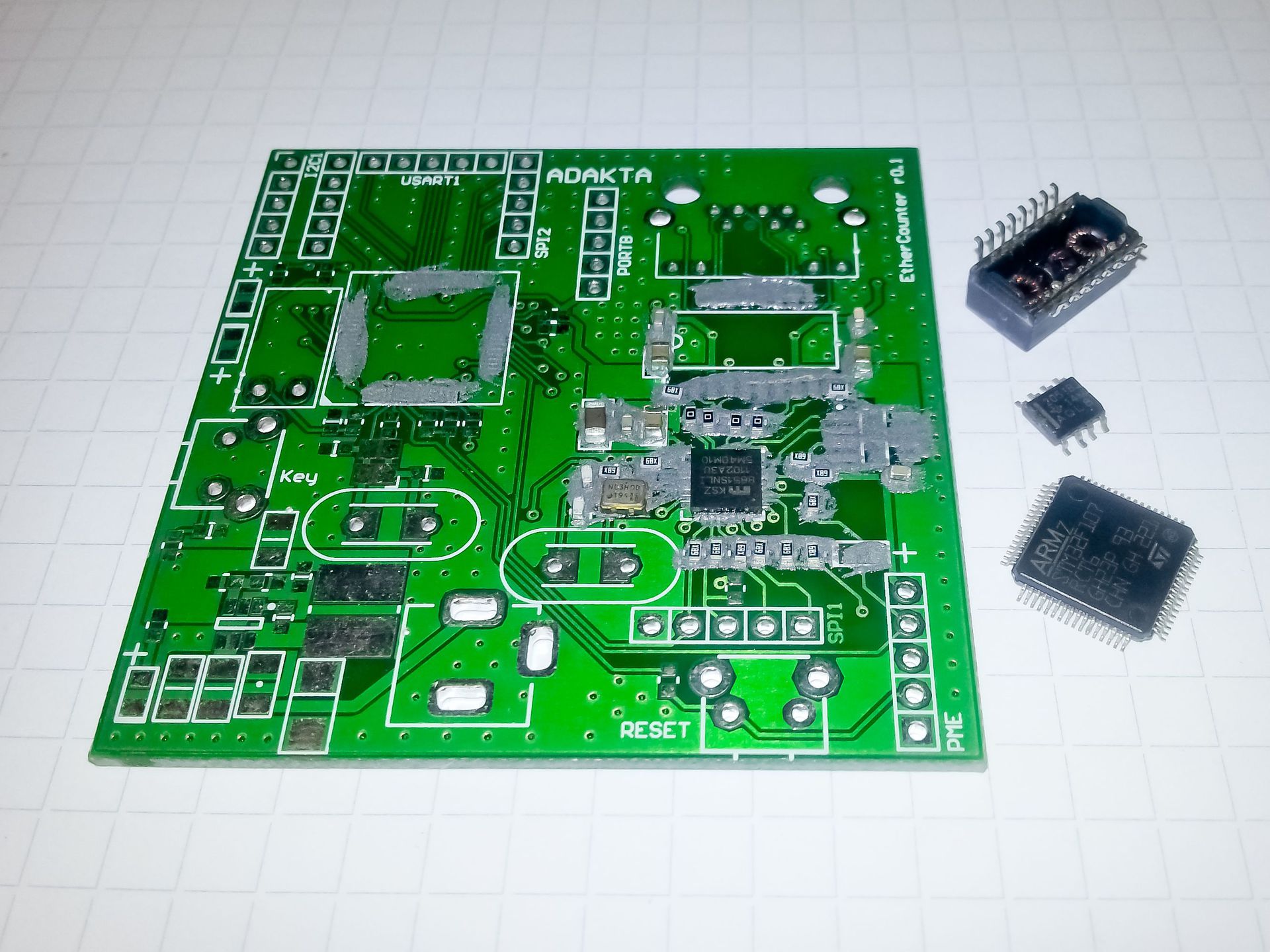
Fig. 4. Installation of components on the board.
If it is necessary to assemble several boards, it is better to install the components on 2 or 4 boards at once, since in this case the probability of the component installation error in the wrong places decreases, this also significantly reduces the overall assembly time. In order to simplify the assembly, the components can be placed in the cash register, then it is more convenient to get them and their location is remembered quickly. After all the necessary components are installed, you can start heating and soldering directly. The board should lie on a flat surface, which is not afraid of strong heat. In the left hand it is necessary to hold the hair dryer, in the right tweezers. The temperature (set on the indicator) is about 390 degrees. - this is a rather high temperature, but it is for this station that this value is normal (also, if there are no special restrictions on the temperature of component soldering). The soldering process is reduced to heating up individual parts of the board (this should be done as evenly as possible), on which the components stand, avoiding overheating and “expansion” of the PCB. For boards with a small number of large polygons and 4-layers, the temperature must be reduced to 360 degrees. During the warm-up period, it is necessary to monitor how the tin melts and at the same time with tweezers to correct the components on the contact pads. Especially watch the components of frame size 0402, as they begin to “float” on the flux and can mix on the board. In the process of soldering, the tin rolls into balls, and “zlipons” are formed between some contact pads; this is removed with the help of a component (for example, a capacitor) captured by tweezers (the main thing to remember is where the component is taken). He collects on himself extra tin, which can then be transferred to large contact pads. All this must be done when the board is warming up, until the flux has dried (it can be applied separately if something did not work out the first time). After soldering the first batch of components, the board looks like this:
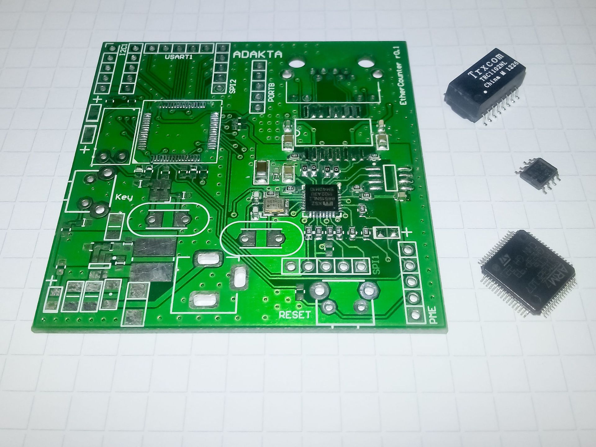
Fig. 5. The first warm up.
I deliberately did not install SOIC to show how it is more convenient to solder it. Before installing the components in the LQFP and SOIC, it is necessary to apply a thin flux on the (tinned!) Contact pads - this will make the soldering of higher quality. Next, install the remaining components. I note that the smaller the pitch of the components, the more precisely they need to be positioned. For example, the STM32F107 in the LQFP64 package will not be lifted with tweezers during the warm-up period, since if it moves at least by half of the output pitch (which is only 0.25 mm), then the tin will be poured onto the adjacent contact pads. SOIC can be raised to preheat the board, as it is relevant for components in a plastic case (relays, connectors, optocouplers, etc.). During the second warm-up, there is no need to warm the entire board, it can be confined to the places where the necessary components are installed. After soldering and washing, the board looks like this:
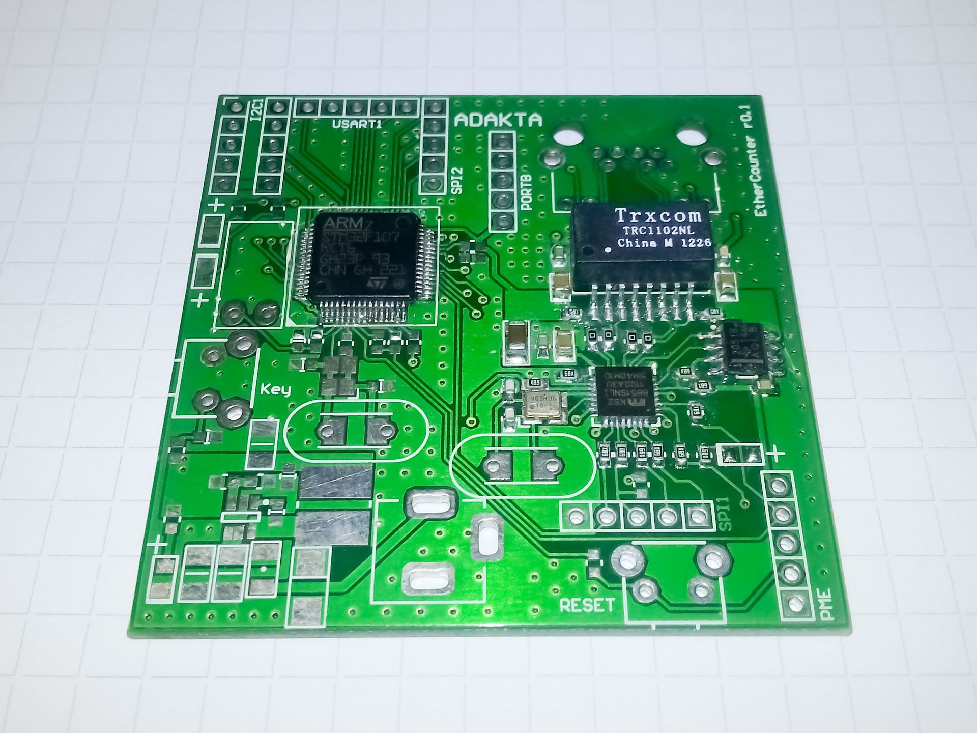
Fig. 6. Second warming up.
This board has two-sided installation. When soldering components on the other side, the lower (previously installed) will begin to move out. To prevent this from happening, it is necessary to install the board on the mounting racks (fasten in the holder) or put several connectors to avoid contact of already soldered components with the surface. For high-quality soldering of lead components, there are also a couple of tricks. I always use solder with a flux (for example RA-0.5), with a diameter of 0.5 mm, respectively. In order to get the solder flowing in correctly between the metallized hole and the component lead, it is necessary that four items touch each other directly during the soldering process: soldering iron, contact pad, component lead and solder, and this is done like this: lean the soldering iron against the lead so that it simultaneously touches the belt “Pad”, then bring the solder and lean it against the soldering iron, as close as possible to the component output and “pad”. As a result, the solder will flow into the heated hole and form a small "influx", after which it is necessary to remove the solder, and then the soldering iron from the output and the "pad."
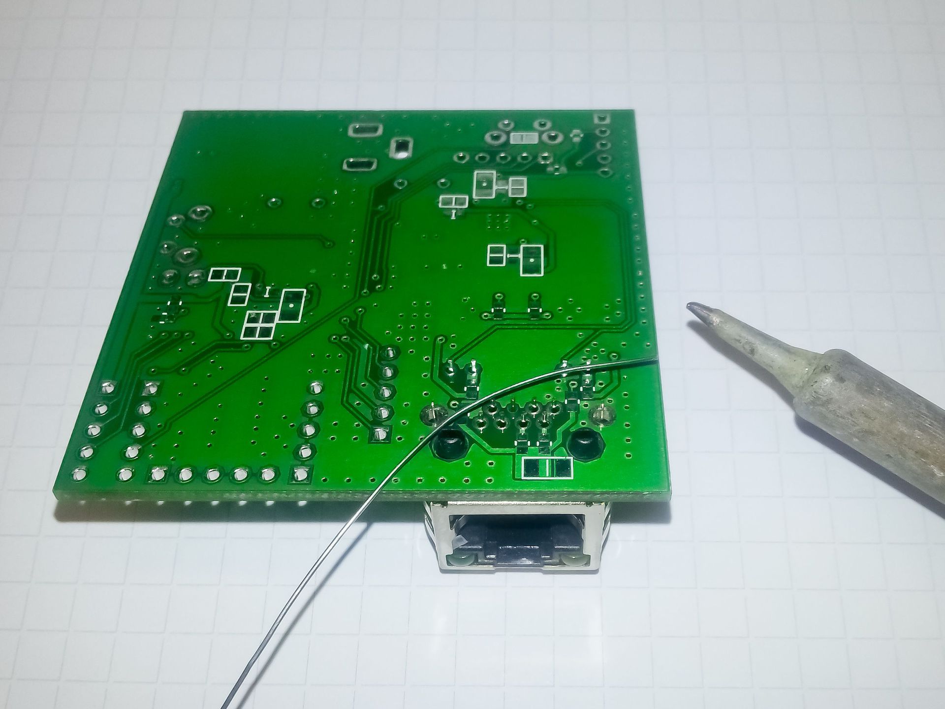
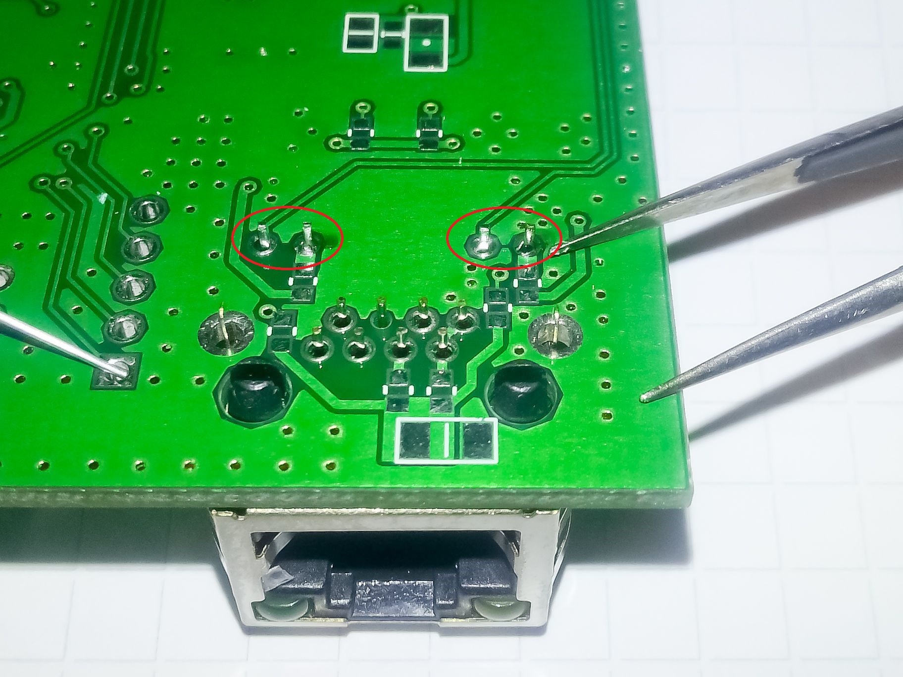
Fig. 7. Soldering of lead components.
In the next article I will talk about installing BGA components (BGA84, BGA78, BGA620 and even BGA1084) using a hair dryer. As well as the pros and cons of installing BGA using a specialized infrared soldering station.
PS: If there are any tips on manual editing, I will listen with pleasure, I can also tell you if something remains unclear.
Today we will talk about how to achieve high quality installation on boards with a large number of components - up to 1500pcs (more can be done with tight installation or 1-2 boards being assembled at the same time - no more). The need for such a complex installation usually arises in the manufacture of the first layout or several samples to ensure the correctness of the trace of the printed circuit board (the main difficult moments) or during one-time production. After receiving such a layout, you can begin to debug the software and make adjustments to the board. The factory assembly, in this case, does not quite fit because of its cost, the preparation of design documentation, selection of components, deadlines, prototyping and much more (under the cut of an 8Mb image).
')
Fig. 1. Finished printed circuit board with components 0402 (reverse side).
So let's start by defining what we need. All surface mounting will be done with a hairdryer and solder paste, as this is many times faster and more qualitatively than with a soldering iron and solder in a wire.
1. Soldering station (for example, Lukey 852D + with nozzle 10mm).
2. Thin non-magnetic tweezers (for installing components).
3. Tweezers with a wide grip (for applying solder paste).
4. Flux (for example, Amtech NC-559-ASM, or another washout free).
5. Solder paste (Solder paste W001).
6. Good light and table.
7. Brush / bath / alcohol for washing the circuit board.
In the process, it will become clear what is what, so we will not focus here. To begin, let's make all the preparations and understand the soldering technology. In order to solder the two surfaces, they must first be tinned, then leaned against each other, heated and after the tin has completely melted - cooled. This is in brief. High-quality soldering has no inclusions, cracks, cracks and has a uniform structure. Cooling of the solder should occur in a stationary state, only in this case it will harden correctly.
Solder paste needs a little refinement. In order for it to overlap well and spread out evenly, it must be diluted with flux in a ratio of approximately 2: 1 (mix well into a homogeneous mass). In some cases, the proportion may vary, for example, if all contact pads have a large area, then the solder should be somewhat thicker and vice versa.
Fig. 2. Solder paste.
In order to step by step explain the entire installation process we solder a part of a small board on which various components are located. The first thing that needs to be done (if the board is only from production and clean) is to apply solder to it. The easiest and fastest, with a certain skill, is a method of applying wide tweezers (or a spatula). Below are the slides of the soldering process. At one time it is necessary to take a small amount of solder and apply it neatly and thinly to the board (as with a spatula). There is no need to put it exclusively on the contact pads, in the process of warming up, because of the large amount of flux, the excess tin will go to the contact pads or turn into balls that need to be transferred to the contact pads manually (later it will be described how to do it).
Fig. 3. The process of applying solder to the board.
Arrangement of components. Not all components can be placed immediately after applying the solder paste. For example, elements in LQFP packages with a lead pitch of less than 0.8 mm should be installed a little later - after the first warm-up with a hair dryer, otherwise there will be short circuits between the leads that will be difficult to remove (of course, you can use a “braid”, but try do without it). So, first we install SMD capacitors, resistors, diodes, etc., components in QFN packages. For this we need a thin non-magnetic tweezers. For quick and easy search for components, I use the search in Altium Designer (the project, respectively, was made there). The search for components is performed from left to right, top to bottom, select a component, for example, a capacitor 100n, find them all and install them on the board.
Fig. 4. Installation of components on the board.
If it is necessary to assemble several boards, it is better to install the components on 2 or 4 boards at once, since in this case the probability of the component installation error in the wrong places decreases, this also significantly reduces the overall assembly time. In order to simplify the assembly, the components can be placed in the cash register, then it is more convenient to get them and their location is remembered quickly. After all the necessary components are installed, you can start heating and soldering directly. The board should lie on a flat surface, which is not afraid of strong heat. In the left hand it is necessary to hold the hair dryer, in the right tweezers. The temperature (set on the indicator) is about 390 degrees. - this is a rather high temperature, but it is for this station that this value is normal (also, if there are no special restrictions on the temperature of component soldering). The soldering process is reduced to heating up individual parts of the board (this should be done as evenly as possible), on which the components stand, avoiding overheating and “expansion” of the PCB. For boards with a small number of large polygons and 4-layers, the temperature must be reduced to 360 degrees. During the warm-up period, it is necessary to monitor how the tin melts and at the same time with tweezers to correct the components on the contact pads. Especially watch the components of frame size 0402, as they begin to “float” on the flux and can mix on the board. In the process of soldering, the tin rolls into balls, and “zlipons” are formed between some contact pads; this is removed with the help of a component (for example, a capacitor) captured by tweezers (the main thing to remember is where the component is taken). He collects on himself extra tin, which can then be transferred to large contact pads. All this must be done when the board is warming up, until the flux has dried (it can be applied separately if something did not work out the first time). After soldering the first batch of components, the board looks like this:
Fig. 5. The first warm up.
I deliberately did not install SOIC to show how it is more convenient to solder it. Before installing the components in the LQFP and SOIC, it is necessary to apply a thin flux on the (tinned!) Contact pads - this will make the soldering of higher quality. Next, install the remaining components. I note that the smaller the pitch of the components, the more precisely they need to be positioned. For example, the STM32F107 in the LQFP64 package will not be lifted with tweezers during the warm-up period, since if it moves at least by half of the output pitch (which is only 0.25 mm), then the tin will be poured onto the adjacent contact pads. SOIC can be raised to preheat the board, as it is relevant for components in a plastic case (relays, connectors, optocouplers, etc.). During the second warm-up, there is no need to warm the entire board, it can be confined to the places where the necessary components are installed. After soldering and washing, the board looks like this:
Fig. 6. Second warming up.
This board has two-sided installation. When soldering components on the other side, the lower (previously installed) will begin to move out. To prevent this from happening, it is necessary to install the board on the mounting racks (fasten in the holder) or put several connectors to avoid contact of already soldered components with the surface. For high-quality soldering of lead components, there are also a couple of tricks. I always use solder with a flux (for example RA-0.5), with a diameter of 0.5 mm, respectively. In order to get the solder flowing in correctly between the metallized hole and the component lead, it is necessary that four items touch each other directly during the soldering process: soldering iron, contact pad, component lead and solder, and this is done like this: lean the soldering iron against the lead so that it simultaneously touches the belt “Pad”, then bring the solder and lean it against the soldering iron, as close as possible to the component output and “pad”. As a result, the solder will flow into the heated hole and form a small "influx", after which it is necessary to remove the solder, and then the soldering iron from the output and the "pad."
Fig. 7. Soldering of lead components.
In the next article I will talk about installing BGA components (BGA84, BGA78, BGA620 and even BGA1084) using a hair dryer. As well as the pros and cons of installing BGA using a specialized infrared soldering station.
PS: If there are any tips on manual editing, I will listen with pleasure, I can also tell you if something remains unclear.
Source: https://habr.com/ru/post/247947/
All Articles