Arduino, Nokia 5110 LCD module and any image
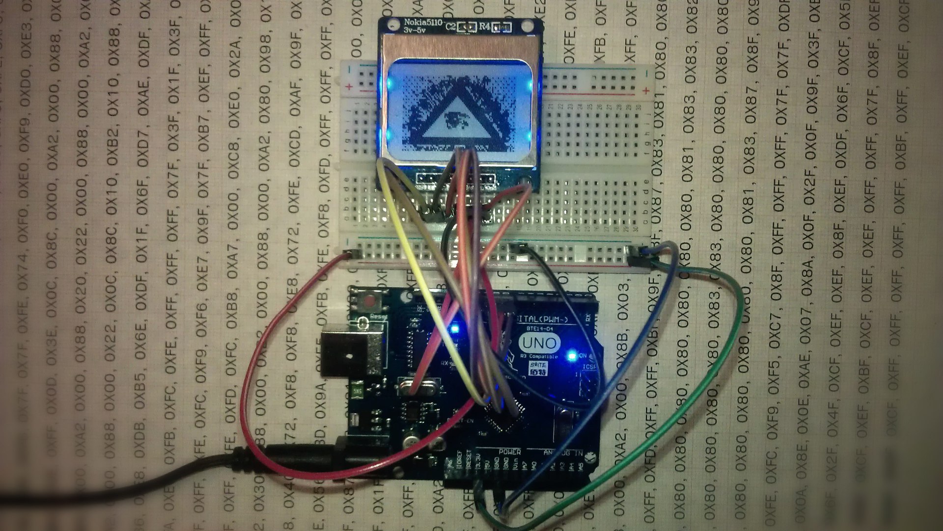
Probably, I, like all Arduino-builders, got some crazy idea in my head. I ordered all the necessary parts in China. We had to wait a very long time, but a clone of the Arduino Uno board and the LCD display Nokia 5110 were delivered here ahead of time. Since before I was not familiar with electronics and programming, I decided not to waste time in vain and began to learn how to display information on this module.
The first thing I did was googling up and got to the publication “Arduino, module Nokia 5110 LCD and Cyrillic” by Shrim . And then I realized that everything that I had planned earlier would not be so easy to do.
I figured out the Cyrillic alphabet, everything is simple there, I will not copy past post, but with the pictures it’s really a problem. There is a task: you need to draw a picture and fill it with a display. Faced the first problem, I went into the Arduino programming environment, I saw that there was no such thing as “Insert - Images”, but I had to write a picture with a certain code in the hex number system . Found several editors, but it was not there. The picture is not adequately displayed. I began to look for problems that can be.
')
Method a bunch of experiments, attempts and samples turned out an algorithm which I will share with you:
1) You need to get the picture itself, in black and white format .bmp with an extension of 84 x 48 pixels.
This can be done in a bunch of ways almost every graphic editor has a function “Save as” where we specify the necessary parameters.
I did in corelDRAW . We get something similar. It is necessary to clarify that the name of the picture must be saved with the Latin keyboard layout, since the next program cannot open it.

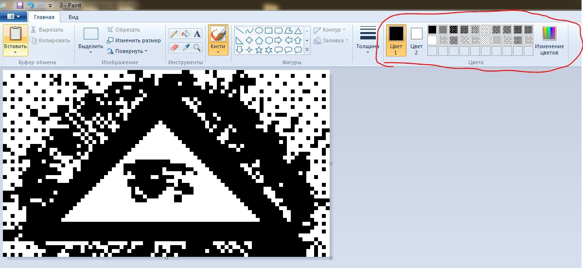
2) If necessary, you can edit the picture in paint, oddly enough, there are some simple and interesting tools.
3) With the help of GLCD Tools we get the hex of the image.
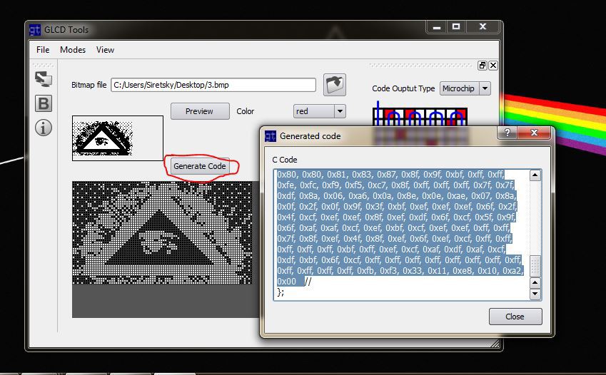
4) Insert this code into the Arduino program code and fill it onto the board:
// SCK - Pin 8 // MOSI - Pin 9 // DC - Pin 10 // RST - Pin 11 // CS - Pin 12 // #include <LCD5110_Graph.h> LCD5110 myGLCD(8,9,10,11,12); extern uint8_t OKO[]; float y; uint8_t* bm; int pacy; void setup() { myGLCD.InitLCD(); } void loop() { myGLCD.clrScr(); myGLCD.drawBitmap(0, 0, OKO, 84, 48); myGLCD.update(); delay(2000); } #include <avr/pgmspace.h> const uint8_t OKO[] PROGMEM={ // hex- GLCD tools }; 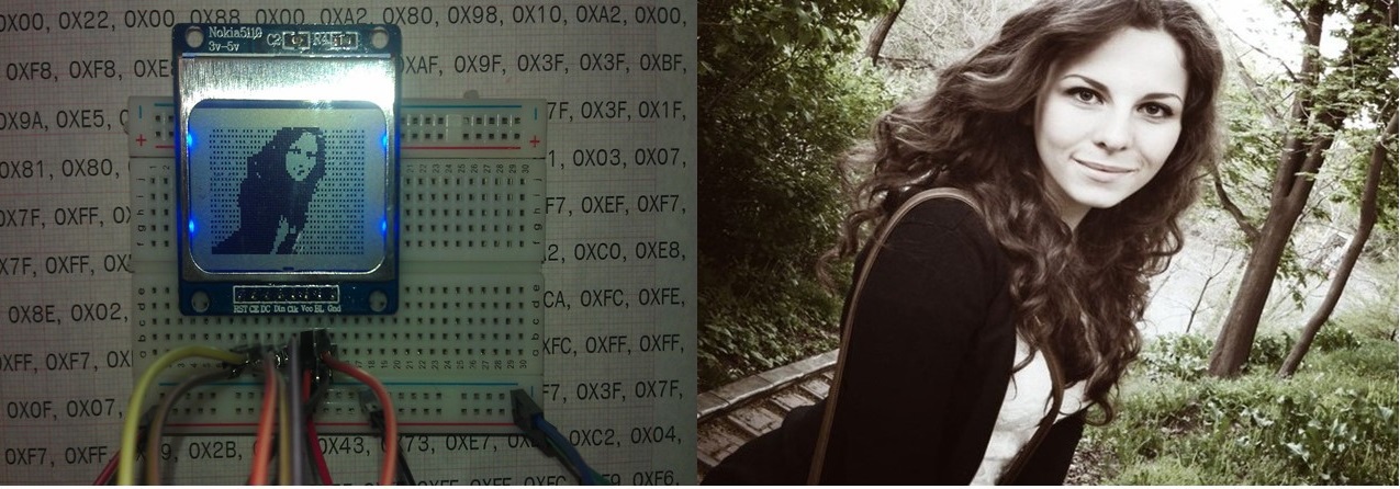
Source: https://habr.com/ru/post/247639/
All Articles