We do tetris under FPGA
Hello!
 On this long New Year’s holiday, I wondered how easy it was to write some kind of simple toy on an FPGA with display and control from the keyboard. This is how one more tetris implementation on FPGA was born: yafpgatetris .
Of course, FPGA games are made more for fun and learning, than for some real “production” tasks, and I’m very far from the “development” of games, you can say this is a new experience for me.
')
If you are interested in how you can run a game without an operating system, implementing it at the lowest level, using triggers and combinational logic, welcome to Cat.
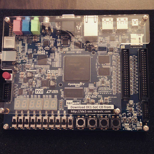
We need "something" where our game will start. One of the easiest ways is to take a devkit with FPGAs and some I / O peripherals. At my disposal was a handkerchief from Terasic called DE1-SoC .

What can I say?
Devkit, as devkit. A lot of peripherals: we will be interested in PS / 2 and VGA plugs from it. For training (in schools or universities) is the thing. For our purposes, we bought it just to play (and to train students) than to implement some of our "production" of ideas.
If suddenly you use DE1-SoC (or similar boards) in your real devices (and not just blink an LED) - share in the comments, it will be interesting.
SoC in the name of the chip means that the chip has both normal FPGA-logic and ARM-processor. Looking ahead, I’ll say that for my task I didn’t use either ARM or some kind of software processor, so you can run my project on your boards with other FPGA chips. If it is interesting to read about raising a bunch of FPGA + ARM, and what bonuses can be obtained from this, I advise you to refer to the article of my colleague Des333 .
You can put various things into the concept of tetris, so I sketched an approximate TK, which I wanted to get:

There are three main parts:
To be honest, at first I thought about doing without the keyboard and using the keys on the whale itself, but surprisingly there were no problems with the keyboard: everything worked out of the box.
To receive commands from the keyboard you need a PS / 2 controller. I used this one .
If we turn a little to theory, then for each key a set of codes is determined, which the keyboard sends when it is pressed or released.
Take the “Enter” key:
Let's see how it looks inside the FPGA:
Normal keystroke:

As you can see, really:
If we hold the key, we get this:

Just comes team 5A with some frequency.
We need a small set of keys:
To determine the type of event, you can get by with a shift register and a small primitive logic, and just skip all the other keys. As part of this game, I decided that it was enough for me to detect keystroke events, and letting go to ignore. When you hold the key, commands will come all the same that the key is pressed, and therefore the player still wants the figure to move or turn over. I admit, I was afraid that the figures would move too unusual, but everything worked out.
After detecting the “event” we are interested in, we put it into the FIFO, from where the “applied logic” of the game will take it. If you did not have PS / 2 on your board, but there are some keys, toggle switches, then it will be enough to write the logic that pressing these buttons translates into “events” and the game will not notice anything.
This controller allows you to connect a mouse, but I have not tried.
On the one hand, the logic is trivial, and is described by the following FSM:
(To be honest, I don’t know if someone uses the “State Machine Viewer” production, if so, share in the comments for what. For all the development time for FPGA, I opened it a couple of times, and then as part of the training).
FSM "communicates" with the following blocks / modules:
Everything is very similar to the "usual" Tetris implementation, which is written in C ++ / Java / etc: various modules perform the role of functions in those languages. Yes, and problems arise the same: the longest was sitting over the figure's coup, the answer was peeped in the quadrapassel code. One option is that you can store a table of all possible turns (for each figure there are four options).
All code is written in Verilog, or to be more precise - on SystemVerilog. On the one hand, SystemVerilog is much more flexible than Verilog, but on the other hand, this leads to the fact that you are not limited, and you want to implement more and more different ryushechek :).
I simplified my life: the current state of the field is stored on registers (instead of internal memory), and because of this (as well as the fact that some things are not optimal) a lot of logic is formed, and the project takes a lot of resources (about 3.2k ALM from 32k ). If you move to memory, you will have to do some things sequentially (for example, moving down the entire field when you need to remove a line that has been filled). Most likely I will not redo the memory usage.
For test purposes, I collected a project for DE0 / DE1 boards (brothers of the board I have, but with budget chips: they have less resources and they are more “younger generation”): the project on resources fits. But…
You can find a lot of information on how to display an image via VGA using FPGAs, for example, in Habré , so I’ll not dwell on this in detail.
In this whale, the output on VGA is made as follows:
Each VGA_CLK clock cycle must be set to a new color value in the RGB model, and then the DAC converts these values to the desired signal level.
As a controller for VGA signals, I took a module from the demos for example on the CD for this whale. It's funny that there is a CD concept, but there is no CD bundled with the board: you need to download the archive from the Internet.
This "controller" Terasic uses in other whales: it is easily googled by the name "vga_time_generator". It is convenient in that you can configure it to any mode of operation (640x480, 800x600, etc), and that gives the coordinates ( pixel_x , pixel_y ) of the current pixel for display. Our task is to substitute the desired color values depending on these coordinates.

I decided that 640x480 on the big monitor doesn’t look very good and moved to 1280x1024, simply by transferring the required values from the standard to the module. Additionally, we had to change the value of VGA_CLK : instead of 25.175 MHz, it was 108 MHz. True, I later regretted it a little, but beauty requires sacrifice.
Consider how to display some primitive objects.
For example:
An orange square of 200x300 pixels is displayed, with the upper left corner located at (100, 100).
Or:
It will be displayed HELLO HABR font with a height of 5 pixels in orange on a black background. (Look at the units in the msg array).
I think it’s clear how you can draw some static messages or a game field.
To display statistics (lines of "Score", "Lines", "Level" and their values), I decided to go along the "classical" path. You can see it, for example, here .
Suppose some kind of logic has already determined which character (read, letter or number) we want to output right now (depending on pixel_x , pixel_y ). To display it, we use a ready-made font table, where units will indicate which pixel you need to paint with the font color, and with zero — the background color, such as:
Many projects (which can be found on the network) with VGA use such a table ( Font ROM ), but they are designed for a 640x480 display: for 1280x1024 it turns out a bit small, so you need to prepare a similar table, but with a “big” font.
The nafe utility helped me in this. At the input it receives a psf file, at the output - a text file with X, in those pixels that need to be drawn. Using your favorite language (or just rewrite the output of the original program), change X to “1” and spaces to “0”, and add a header to make the mif file (which is then used to initialize the ROM).
The largest font I found in my psf format was 32x16, and, in principle, it was enough for this task, but I would like to do a little more. As far as I understand, there are no restrictions, and with the help of this utility you can prepare a ROM with any symbols (for example, Russian letters).
However, for the yafpgatetris header and the GAMEOVER message , this size seemed to me small, and I decided to display these messages in the same way as the HELLO HABR line in the example above. The only question is how to prepare msg , because I really didn't want to do this with pens.
Immediately came up with a relatively simple bicycle (?) Solution:
The resulting set of zeros and ones can also be put in ROM (in other than the font, of course).
A couple of photos from the “development in process” series:
Sources:
https://github.com/johan92/yafpgatetris
Video:
I tried to make the project as parameterizable as possible, and logically divided into parts, so if you want to make “races” on the basis of my project, where you have to dodge other machines, or a snake, you just need to write your main_game_logic and slightly correct the conclusion (if necessary) .
It took about 5 days to develop, if we consider the “pure time”: I had to tinker with the figure's coup (in fact, rewrite the algorithm twice), it took a lot of time to select colors, sizes, alignment and positioning of messages. The internal perfectionist all the time demanded that the internal designer move something, increase / decrease something, etc. For myself, I learned that GUI development is not mine) As a result, I took the colors for the figures from Tetris application on Vkontakte.
If you bought a whale and want to learn how to develop under FPGA, I do not recommend doing Tetris directly as a first project. Start with LEDs, segment indicators, clocks, and other classic things. When this passes, you can try Tetris, or some other simple game. I hope my project will help in this endeavor.
Thanks for attention! If you have questions, ask without a doubt.
On this long New Year’s holiday, I wondered how easy it was to write some kind of simple toy on an FPGA with display and control from the keyboard. This is how one more tetris implementation on FPGA was born: yafpgatetris .Of course, FPGA games are made more for fun and learning, than for some real “production” tasks, and I’m very far from the “development” of games, you can say this is a new experience for me.
')
If you are interested in how you can run a game without an operating system, implementing it at the lowest level, using triggers and combinational logic, welcome to Cat.
About girls
We need "something" where our game will start. One of the easiest ways is to take a devkit with FPGAs and some I / O peripherals. At my disposal was a handkerchief from Terasic called DE1-SoC .
What can I say?
Devkit, as devkit. A lot of peripherals: we will be interested in PS / 2 and VGA plugs from it. For training (in schools or universities) is the thing. For our purposes, we bought it just to play (and to train students) than to implement some of our "production" of ideas.
If suddenly you use DE1-SoC (or similar boards) in your real devices (and not just blink an LED) - share in the comments, it will be interesting.
SoC in the name of the chip means that the chip has both normal FPGA-logic and ARM-processor. Looking ahead, I’ll say that for my task I didn’t use either ARM or some kind of software processor, so you can run my project on your boards with other FPGA chips. If it is interesting to read about raising a bunch of FPGA + ARM, and what bonuses can be obtained from this, I advise you to refer to the article of my colleague Des333 .
What we want to get
You can put various things into the concept of tetris, so I sketched an approximate TK, which I wanted to get:
- Standard set of figures. Their behavior should be as similar to the usual.
- The game is colorful. Each figure has its own color.
- The figures are generated randomly with a uniform distribution.
- There should be a window in which the next figure is displayed.
- There should be information about the state of the game: the number of points, the number of lines removed, the current level.
- Points are awarded on a “progressive” scale: the more lines you remove at once, the more points.
- The higher the level, the greater the speed of the falling figures.
- The “end of the game” is detected correctly, there is an opportunity to start a new game.
- User input is entered from the keyboard (PS / 2).
- Displaying the status of the field and other things happens on a normal display via the VGA interface.
Project outline
There are three main parts:
- User input. We accept data from the keyboard and “work” on the system.
- All that relates to the game itself. In fact, FSM (finite-state machine), which accepts “requests” from the player, and “does everything”: generates new figures, moves them, removes lines, and so on.
- Displays the status of the game. Draw to the display via the VGA interface.
PS / 2
To be honest, at first I thought about doing without the keyboard and using the keys on the whale itself, but surprisingly there were no problems with the keyboard: everything worked out of the box.
To receive commands from the keyboard you need a PS / 2 controller. I used this one .
If we turn a little to theory, then for each key a set of codes is determined, which the keyboard sends when it is pressed or released.
Take the “Enter” key:
- Make: 5A
- Break: F0, 5A.
Let's see how it looks inside the FPGA:
Normal keystroke:
As you can see, really:
- Press the key, comes 5A.
- Release: F0 comes, after it 5A.
- Press again: comes 5A and so on.
If we hold the key, we get this:
Just comes team 5A with some frequency.
We need a small set of keys:
- ordinary arrows - to control the figure.
- n - to start a new game.
To determine the type of event, you can get by with a shift register and a small primitive logic, and just skip all the other keys. As part of this game, I decided that it was enough for me to detect keystroke events, and letting go to ignore. When you hold the key, commands will come all the same that the key is pressed, and therefore the player still wants the figure to move or turn over. I admit, I was afraid that the figures would move too unusual, but everything worked out.
After detecting the “event” we are interested in, we put it into the FIFO, from where the “applied logic” of the game will take it. If you did not have PS / 2 on your board, but there are some keys, toggle switches, then it will be enough to write the logic that pressing these buttons translates into “events” and the game will not notice anything.
This controller allows you to connect a mouse, but I have not tried.
The main logic of the game
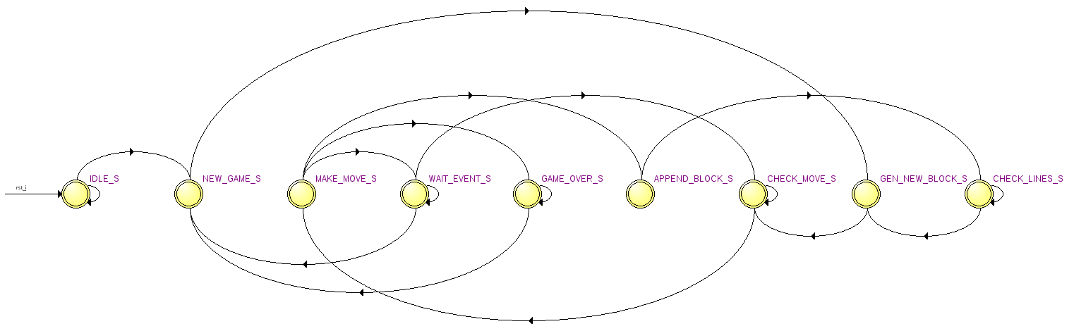
On the one hand, the logic is trivial, and is described by the following FSM:
(To be honest, I don’t know if someone uses the “State Machine Viewer” production, if so, share in the comments for what. For all the development time for FPGA, I opened it a couple of times, and then as part of the training).
FSM "communicates" with the following blocks / modules:
- gen_sys_event is a timer that counts the time after which it is necessary to automatically move the figure down.
- gen_next_block is a new figure generator.
- check_move - check if the current “move” can be performed.
- tetris_stat - the accumulation of "statistics".
- user_input - reads the event that the user "made".
Everything is very similar to the "usual" Tetris implementation, which is written in C ++ / Java / etc: various modules perform the role of functions in those languages. Yes, and problems arise the same: the longest was sitting over the figure's coup, the answer was peeped in the quadrapassel code. One option is that you can store a table of all possible turns (for each figure there are four options).
All code is written in Verilog, or to be more precise - on SystemVerilog. On the one hand, SystemVerilog is much more flexible than Verilog, but on the other hand, this leads to the fact that you are not limited, and you want to implement more and more different ryushechek :).
I simplified my life: the current state of the field is stored on registers (instead of internal memory), and because of this (as well as the fact that some things are not optimal) a lot of logic is formed, and the project takes a lot of resources (about 3.2k ALM from 32k ). If you move to memory, you will have to do some things sequentially (for example, moving down the entire field when you need to remove a line that has been filled). Most likely I will not redo the memory usage.
For test purposes, I collected a project for DE0 / DE1 boards (brothers of the board I have, but with budget chips: they have less resources and they are more “younger generation”): the project on resources fits. But…
Hidden text
... right out of the box does not work:
- Quartus will swear at some things in the qsf file, because I collected for the 14th quarter, where there is no Cyclone II / III. Early versions of the quartus of these things do not know: you have to remove these lines in the qsf file with pens, and then, in the sense, put the same daws in the GUI of the quartus.
- It does not fit in the frequency: the “main” frequency in this project is 108 MHz (the main_game_logic itself works on it and the drawing is on VGA). Slightly running ahead, the frequency is 108 MHz - because the resolution is 1280x1024, if you use 640x480, then there will be a frequency of 25 MHz, and it will fit.
- You may have to regenerate mega functions for PLL and FIFO, because They were created for Cyclone V.
- The display may need to be slightly edited (choose other colors), because there, for each color, only four bits are allocated (as I understand it), against eight, as in this board.
Display
You can find a lot of information on how to display an image via VGA using FPGAs, for example, in Habré , so I’ll not dwell on this in detail.
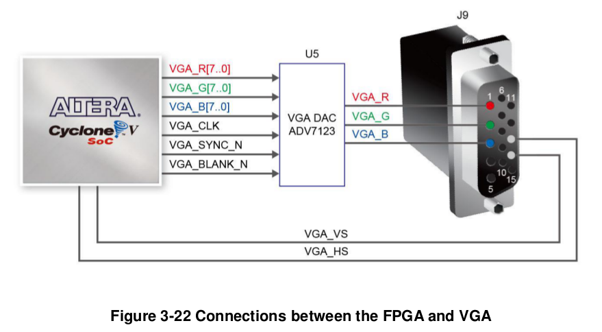
In this whale, the output on VGA is made as follows:
Each VGA_CLK clock cycle must be set to a new color value in the RGB model, and then the DAC converts these values to the desired signal level.
As a controller for VGA signals, I took a module from the demos for example on the CD for this whale. It's funny that there is a CD concept, but there is no CD bundled with the board: you need to download the archive from the Internet.
This "controller" Terasic uses in other whales: it is easily googled by the name "vga_time_generator". It is convenient in that you can configure it to any mode of operation (640x480, 800x600, etc), and that gives the coordinates ( pixel_x , pixel_y ) of the current pixel for display. Our task is to substitute the desired color values depending on these coordinates.
I decided that 640x480 on the big monitor doesn’t look very good and moved to 1280x1024, simply by transferring the required values from the standard to the module. Additionally, we had to change the value of VGA_CLK : instead of 25.175 MHz, it was 108 MHz. True, I later regretted it a little, but beauty requires sacrifice.
Consider how to display some primitive objects.
For example:
`define RGB_BLACK 24'h00_00_00 `define RGB_ORANGE 24'hFF_A5_00 logic [23:0] vga_data; localparam START_X = 100; localparam START_Y = 100; localparam END_X = START_X + 200 - 1; localparam END_Y = START_Y + 300 - 1; always_comb begin vga_data = `RGB_BLACK; if( ( pixel_x >= START_X ) && ( pixel_x <= END_X ) && ( pixel_y >= START_Y ) && ( pixel_y <= END_Y ) ) vga_data = `RGB_ORANGE; end assign { r, g, b } = vga_data; An orange square of 200x300 pixels is displayed, with the upper left corner located at (100, 100).
Or:
`define RGB_BLACK 24'h00_00_00 `define RGB_ORANGE 24'hFF_A5_00 logic [23:0] vga_data; localparam MSG_X = 56; localparam MSG_Y = 5; logic [0:MSG_Y-1][0:MSG_X-1] msg; assign msg[0] = 56'b10010011110010000010000001100000001001000110001110001110; assign msg[1] = 56'b10010010000010000010000010010000001001001001001001001001; assign msg[2] = 56'b11110011110010000010000010010000001111001111001111001111; assign msg[3] = 56'b10010010000010000010000010010000001001001001001001001110; assign msg[4] = 56'b10010011110011110011110001100000001001001001001110001001; logic [$clog2(MSG_X)-1:0] msg_pix_x; logic [$clog2(MSG_Y)-1:0] msg_pix_y; localparam START_MSG_X = 100; localparam START_MSG_Y = 100; localparam END_MSG_X = START_MSG_X + MSG_X - 1; localparam END_MSG_Y = START_MSG_Y + MSG_Y - 1; assign msg_pix_x = pixel_x - START_MSG_X; assign msg_pix_y = pixel_y - START_MSG_Y; always_comb begin vga_data = `RGB_BLACK; if( ( pixel_x >= START_MSG_X ) && ( pixel_x <= END_MSG_X ) && ( pixel_y >= START_MSG_Y ) && ( pixel_y <= END_MSG_Y ) ) begin if( msg[ msg_pix_y ][ msg_pix_x ] ) begin vga_data = `RGB_ORANGE; end end end assign { r, g, b } = vga_data; It will be displayed HELLO HABR font with a height of 5 pixels in orange on a black background. (Look at the units in the msg array).
I think it’s clear how you can draw some static messages or a game field.
Display lines
To display statistics (lines of "Score", "Lines", "Level" and their values), I decided to go along the "classical" path. You can see it, for example, here .
Suppose some kind of logic has already determined which character (read, letter or number) we want to output right now (depending on pixel_x , pixel_y ). To display it, we use a ready-made font table, where units will indicate which pixel you need to paint with the font color, and with zero — the background color, such as:
"00000000", -- 0 "00000000", -- 1 "00010000", -- 2 * "00111000", -- 3 *** "01101100", -- 4 ** ** "11000110", -- 5 ** ** "11000110", -- 6 ** ** "11111110", -- 7 ******* "11000110", -- 8 ** ** "11000110", -- 9 ** ** "11000110", -- a ** ** "11000110", -- b ** ** "00000000", -- c "00000000", -- d "00000000", -- e "00000000", -- f Many projects (which can be found on the network) with VGA use such a table ( Font ROM ), but they are designed for a 640x480 display: for 1280x1024 it turns out a bit small, so you need to prepare a similar table, but with a “big” font.
The nafe utility helped me in this. At the input it receives a psf file, at the output - a text file with X, in those pixels that need to be drawn. Using your favorite language (or just rewrite the output of the original program), change X to “1” and spaces to “0”, and add a header to make the mif file (which is then used to initialize the ROM).
The largest font I found in my psf format was 32x16, and, in principle, it was enough for this task, but I would like to do a little more. As far as I understand, there are no restrictions, and with the help of this utility you can prepare a ROM with any symbols (for example, Russian letters).
However, for the yafpgatetris header and the GAMEOVER message , this size seemed to me small, and I decided to display these messages in the same way as the HELLO HABR line in the example above. The only question is how to prepare msg , because I really didn't want to do this with pens.
Immediately came up with a relatively simple bicycle (?) Solution:
- Type the text of the desired font and size in Paint / GIMP.
- We save in PNG without compression and smoothing.
- We use some kind of ready-made library to read the PNG file and output 0 for each pixel if “color is white”, 1 if “color is black”.
The resulting set of zeros and ones can also be put in ROM (in other than the font, of course).
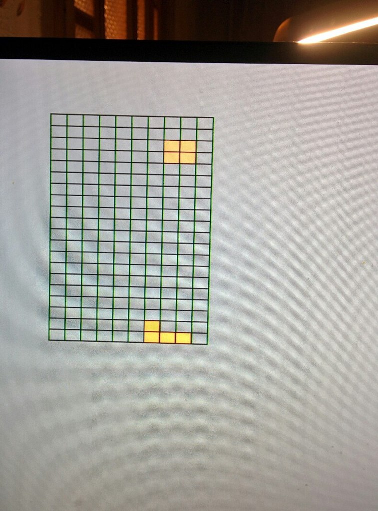
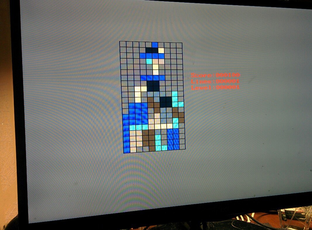
A few pictures
A couple of photos from the “development in process” series:
Hidden text
We learned how to display the field: the figures just fall down and all are the same color.
Added statistics and different colors. Eyes vyvaglaznye :)
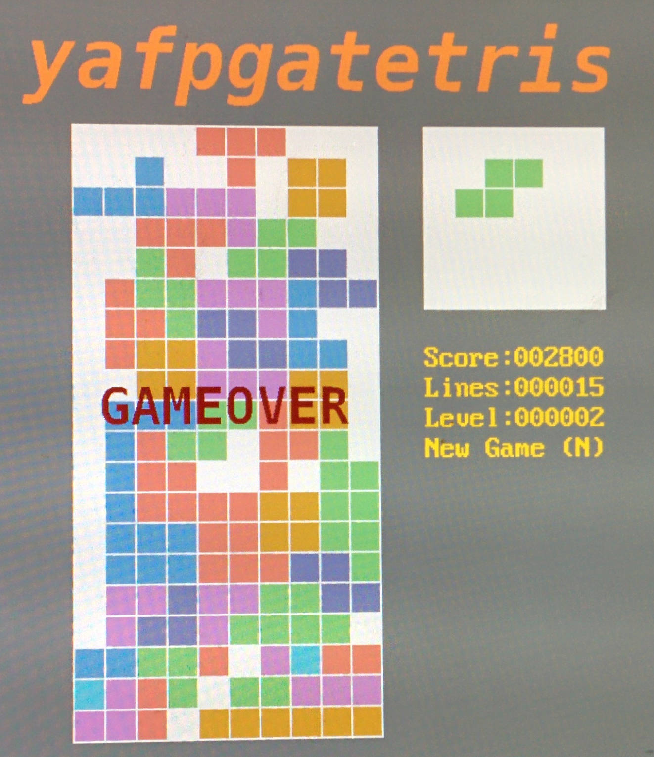
Well, the final version is at the beginning of the article :)
PS
To be honest, I don’t know why when photographing such “divorces” on the display, maybe I didn’t turn on any settings in the VGA-peel, or just not lucky ...

Added statistics and different colors. Eyes vyvaglaznye :)

Well, the final version is at the beginning of the article :)
PS
To be honest, I don’t know why when photographing such “divorces” on the display, maybe I didn’t turn on any settings in the VGA-peel, or just not lucky ...
Results
Sources:
https://github.com/johan92/yafpgatetris
Video:
I tried to make the project as parameterizable as possible, and logically divided into parts, so if you want to make “races” on the basis of my project, where you have to dodge other machines, or a snake, you just need to write your main_game_logic and slightly correct the conclusion (if necessary) .
It took about 5 days to develop, if we consider the “pure time”: I had to tinker with the figure's coup (in fact, rewrite the algorithm twice), it took a lot of time to select colors, sizes, alignment and positioning of messages. The internal perfectionist all the time demanded that the internal designer move something, increase / decrease something, etc. For myself, I learned that GUI development is not mine) As a result, I took the colors for the figures from Tetris application on Vkontakte.
If you bought a whale and want to learn how to develop under FPGA, I do not recommend doing Tetris directly as a first project. Start with LEDs, segment indicators, clocks, and other classic things. When this passes, you can try Tetris, or some other simple game. I hope my project will help in this endeavor.
Thanks for attention! If you have questions, ask without a doubt.
Source: https://habr.com/ru/post/247535/
All Articles