Express Specialist
Do you remember your first computer? I remember. It was a ZX compatible PC Spectrum. It was in the 89th year. I don’t know for sure if his father bought it or changed it for something, but a PC appeared in the house and it all started. It was on it that I wrote my first programs and mastered Basic. Then, when I was in grades 7-9, there were also PK-01 Lviv and Vector 06C.
In grade 11 there was an attempt to assemble Orion-128. After school, I went to study in Tomsk, and all I managed to do at that moment was to drill holes and paint tracks. So it never came to pickling the board. Already in high school, I had PC-compatible PCs and old computers in general became unnecessary. But the idea to build your own PC continued to fly in the air for almost 14 years. Zateu warmed up a dispute with the father of Orion assembly times. Apparently, to motivate me to build, he said that I would not be able to assemble it.
In the fall of 2014, collecting the next design on the Arduino, I wondered if it was possible to assemble the same Orion-128 on it, well, or, more simply, Radio-86RK, for example. Thinking over this idea, I decided to realize a long-standing school dream - a PC assembled on my own. It is said - will be done. The confidence was given by Alexey Morozov’s videos on repairing old computers and articles in various forums devoted to retro PCs. In these forums, there were people who constantly collected retro PCs.
And I began to look for a suitable scheme, without scarce details - ideally, only small logic, a processor and an I / O port. At first I looked closely at the PC Leningrad, but could not find it in the city of the Z80, and it was a long time to order it. As a result, he stopped at the scheme PC Specialist Express. The scheme, I think, is ideal for a beginner, as it contains a minimum of details, and is simple in assembly and adjustment.
')
A very high-quality scheme was found on the site www.spetsialist-mx.ru , the man with the nickname Fifan redrawn it, for which he thanks a lot.
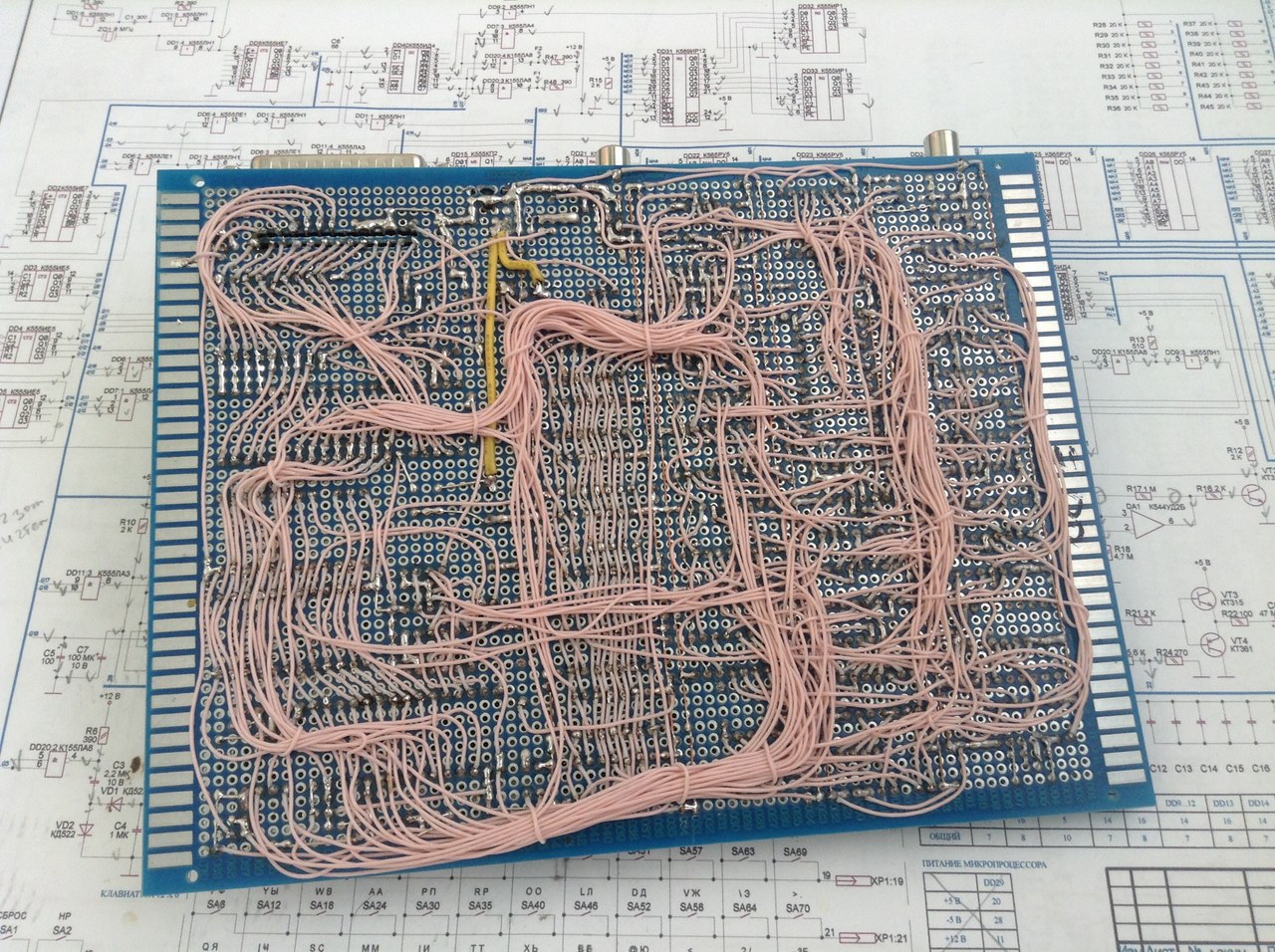
The next question is to make a PCB using LUT technology, or to plunge into the past and assemble it by mounting using the MGTF wire, as most amateurs did in the 80s. Since the main idea was to assemble the device, and not to find a great practical use for it, due to poor performance, I stopped at the second option.
All parts for assembly cost about 4000 tenge (about 1000 rubles). I decided to put all the chips in the sockets.
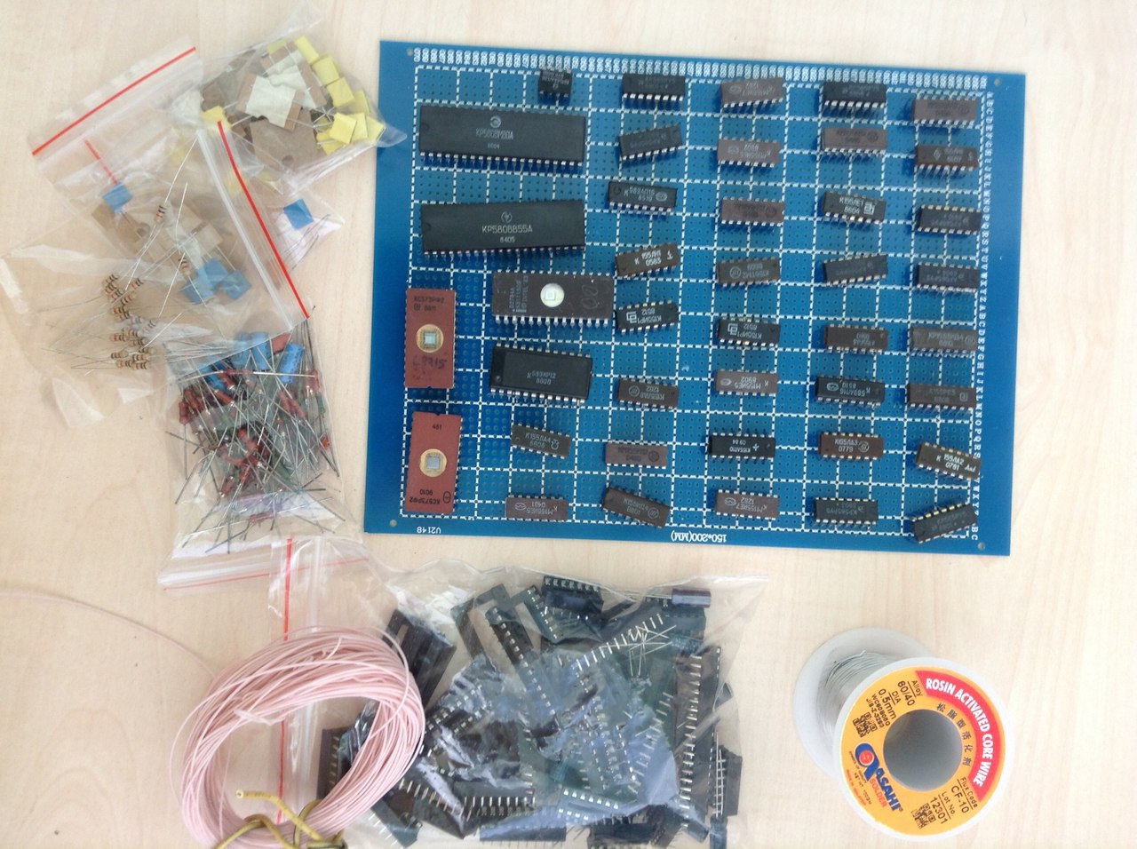
On the first day I collected a clock generator and counters. MGTF soldering was very simple. Someone writes on the Internet that you need to clean the ends, I just bit off the wire with wire cutters, after which I applied a small amount of rosin on the tip and heated it with a soldering iron with a drop of tin. The braid at the same time slipped by about 0.5 mm, this is just enough to solder it.
Itching to feed power, and make sure that the generator and the meters work. But there was neither a frequency meter nor an oscilloscope at hand, so it was decided to complete the installation, and only then debug it.
The second session was outlined only a week later on the weekend. For 2 days off, a sync generator, registers for imaging, multiplexers and RAM were added.
After another work week, I sat down again for soldering. Over the weekend, I drank almost the entire scheme. Only the port of the keyboard and the tape recorder were not soldered. There was also a problem with connecting the power to the processor, there were conflicting information on the diagram.
By that time, I met Alexei Morozov (VINXRU) and Andrey Anisheko. Alexey helped to deal with the findings of the processor. Looking ahead, I will say that the guys helped a lot in the process of building and debugging the PC. Thank you very much for this!
At this point, the computer had an almost finished look.
His hands itched rather turn it on. Therefore, once soldered stabilizers, decide to check the formation of -5 volts. For this, I installed a 155LA3 clock chip, counters, and an inverter in the microchips. I turned on the power, and here they are, honest -5.6 volts on the microprocessor's leg! Joy that day there was no limit.

Only one moment made me think - the stabilizer 7805 (even planted on the radiator) warmed up so that it could not be touched. And this is only 4 chips in the power circuit.
The second stabilization option was not original. I just planted in parallel 2 cases 7805 on a larger radiator. They began to warm up less, but still it was impossible to touch them after 10 minutes of work. This circumstance made it necessary to buy an external power supply unit at + 5V (4A) and + 12V (1A). After that, problems with power supply no longer occurred, besides, the presence of a voltage of 12V made it possible to abandon the 7812 stabilizer.
After the entire circuit has been assembled, it remains to record the Loader and Monitor in the ROM. It was not as easy as it seemed.
I did not have a programmer. I started to assemble a handheld programmer, but once again looking at the code of the Loader and Monitor, I decided to leave this dole plan, although in the 80s many people went this way. It was not possible to find the programmer of such ancient ROMs in Almaty, and we did not want to order and lose a month. Therefore, I started experimenting with Arduino. At first he soldered the shield, and learned how to read the contents of the ROM. Both chips were not empty. And judging by the code, it was most likely firmware from AON. There was another problem - they need to be erased. At school age, my father constantly told me that it was impossible for the crystal ROM to get light, they are erased from it. I put both roms for a few days on the sun. Over the weekend, I checked the contents again - not a bit of information was erased.
Messages on the forums, as well as Alexei Morozov, spoke about two ways of erasing - this is an internal flask from a DRL lamp with a choke, which emits a large amount of harmful ozone, and a UV germicidal medical lamp. Erasing DRL-Coy takes about 3 hours, a UV lamp for about 15 minutes. Without thinking twice, I bought OUFK-09-1, especially since I had colds at home, and quartzing the room would have been the way. Both microcircuits were cleaned in 10 minutes. Now you need to learn how to write a shield in ROM. It took a little more time. I originally planned to make a program-programmer on Visual Basic with sending data to Arduinka via the COM port, but with this thought after a day or two, I decided to simplify the scheme, namely, to connect an SD card to Arduinka, where the firmware would be located there would be 2 buttons - Read and Write. The execution of the program was displayed in the COM port and displayed on the PC in the port monitor.
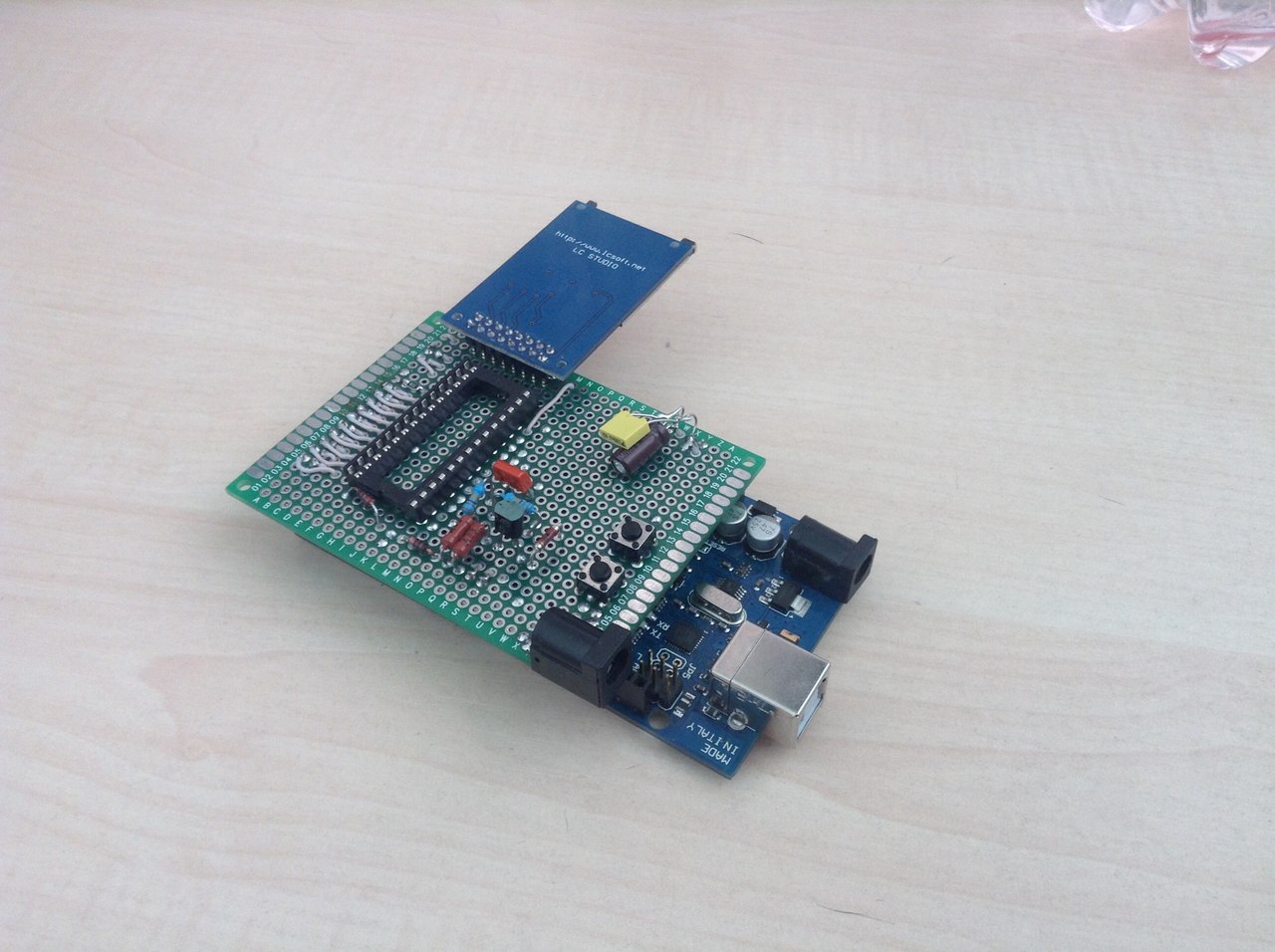
The result was such a shield:
I downloaded the Downloader and Monitor in the ROM, which were also found on the Fifan site. I turned on the power and the computer did not work. Well, it was worth the wait. By that time, the frequency meter had already been found, and it quickly became clear that the RAS signal was not being formed correctly, its frequency should have been about 2 MHz, but it was 6, then 4. Soldering the socket from IR12 gave its results, the signal started to form correctly. This problem took about a week. But there was still no image.
On the advice of Andrew, I flashed a test program into the ROM, and sounds began to come from the speaker. This meant that the processor, buffers, ROM, and I / O port worked correctly.
After a brief trial, it turned out that the output transistor gives the signal level that the television did not have enough to work. Having made small changes to the scheme of this site, the image finally appeared! But the screen was divided into 6 sections, and the image was displayed only in 3 of them.
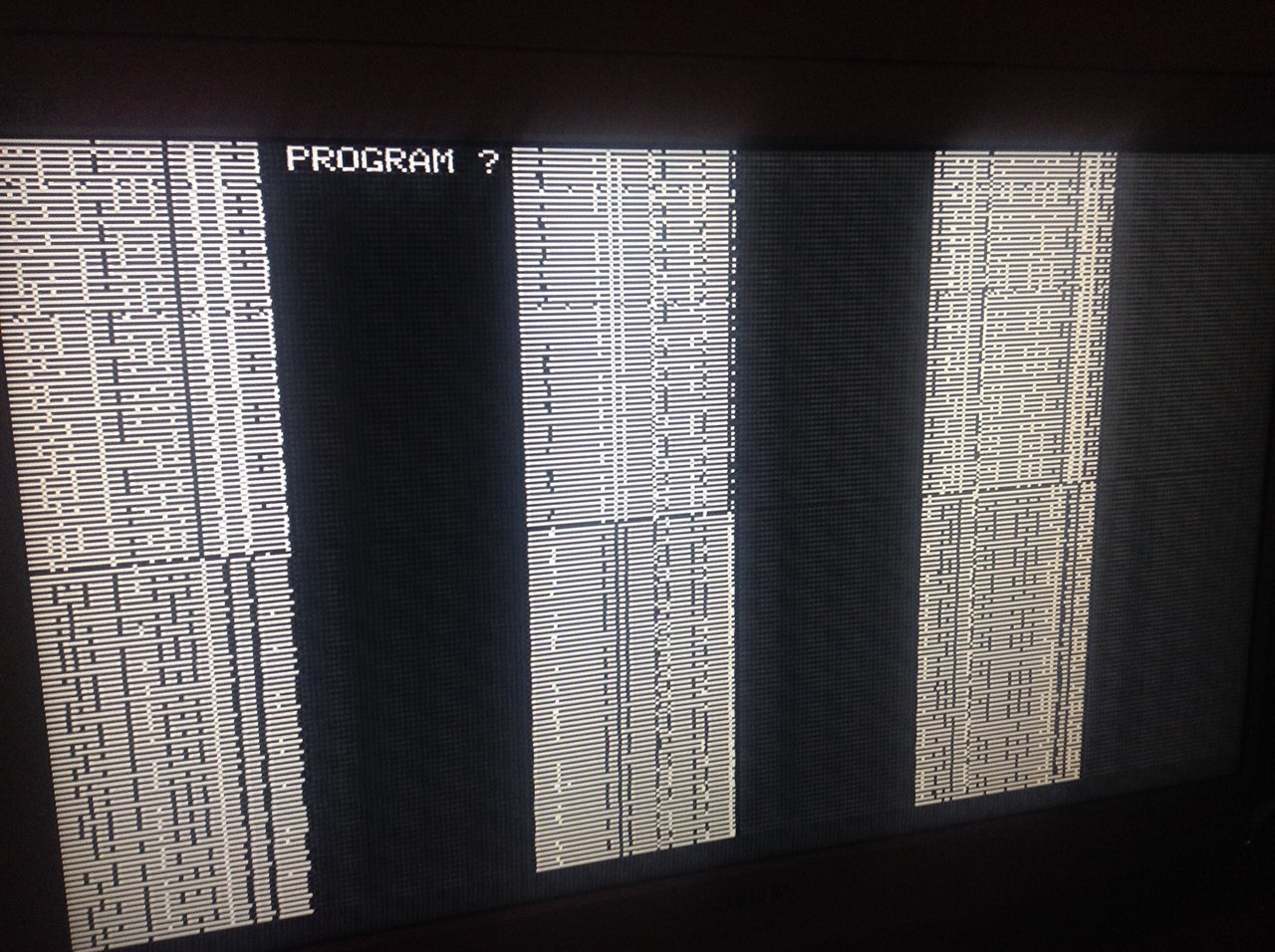
Suspicions fell on the multiplexers. But no matter how I rearranged them, the image did not change. The test dial of the board tester also did not give anything - all connections were in place. After spending a few more days on this problem and sorting through a couple more options (matching capacitors in the divider circuits and the processor SYNC), I found the reason - there was still one contact in the multiplexer. The image went, but with noise in the form of vertical lines, except for this 2 RAM shone as defective.
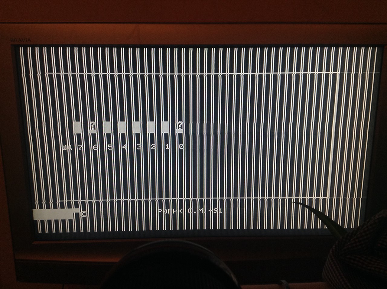
The rearrangement of microcircuits in places did not give any result, which means another one is not. So it turned out. Food was absent on them. Apparently melted the solder when dopai smoothing capacitors.
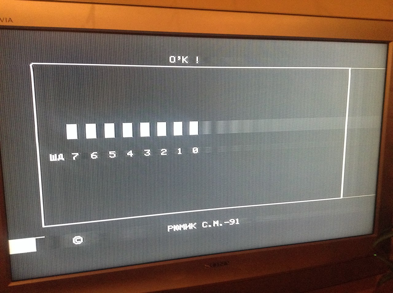
After that, the picture became what it should be. The test program showed that everything is normal - the image is formed, the RAM is normal.
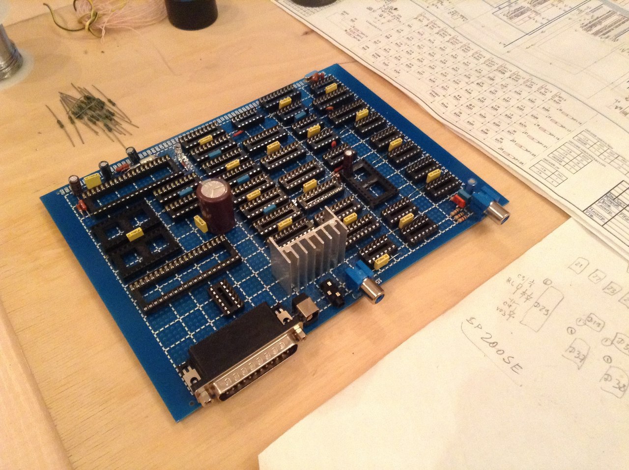
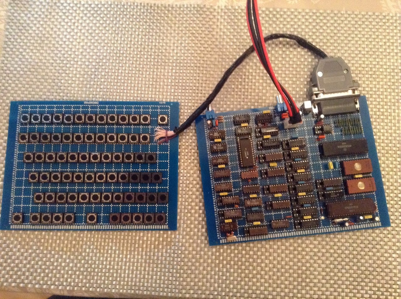
The next step is the keyboard. The easiest way would be to take a PS / 2 keyboard and connect it via the AVR controller. But after walking around with this idea until the end of the work week, I decided to assemble the keyboard according to the original scheme. As a result, the final look of the PC is:
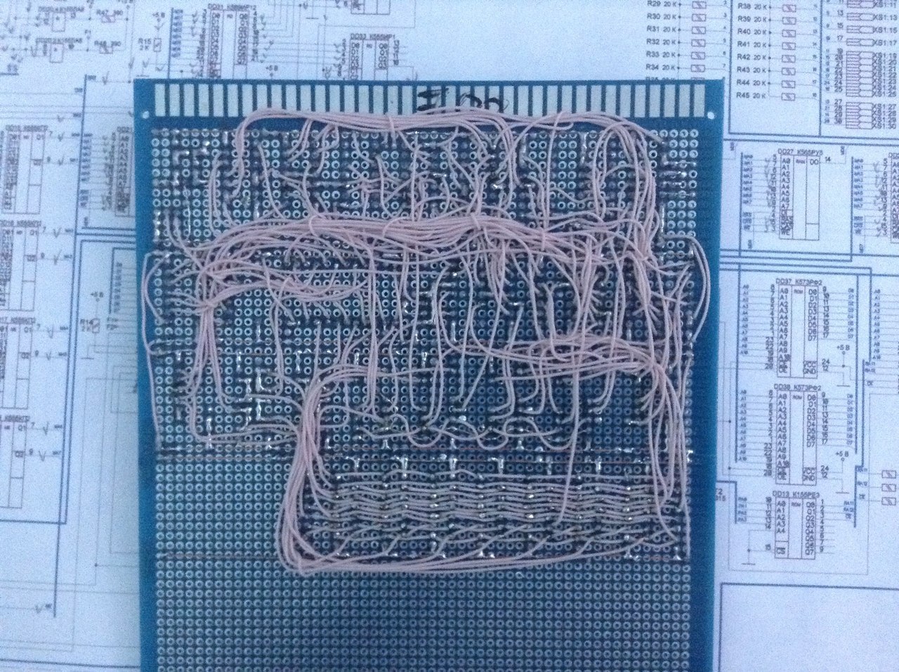
And the view from the side of the installation:
It remains to put it in the human case, and to remake the keyboard connector (the idea with the 25-foot connector turned out to be cumbersome, therefore not very successful) and I will assume that the assembly is complete. The computer will take place on the shelf next to the old ZX-Spectrum, PK01-Lviv, Vector-06Ts and Microsheys, which was recently presented to me, and which requires minor repairs.
On the one hand, it is sad that one long-time dream has become less, but on the other hand, they are needed to come true. It is still sad that the father did not live to the moment when he lost the argument.
Conclusion? Scratched, or when itched hands - go for it, it's worth it!
In grade 11 there was an attempt to assemble Orion-128. After school, I went to study in Tomsk, and all I managed to do at that moment was to drill holes and paint tracks. So it never came to pickling the board. Already in high school, I had PC-compatible PCs and old computers in general became unnecessary. But the idea to build your own PC continued to fly in the air for almost 14 years. Zateu warmed up a dispute with the father of Orion assembly times. Apparently, to motivate me to build, he said that I would not be able to assemble it.
In the fall of 2014, collecting the next design on the Arduino, I wondered if it was possible to assemble the same Orion-128 on it, well, or, more simply, Radio-86RK, for example. Thinking over this idea, I decided to realize a long-standing school dream - a PC assembled on my own. It is said - will be done. The confidence was given by Alexey Morozov’s videos on repairing old computers and articles in various forums devoted to retro PCs. In these forums, there were people who constantly collected retro PCs.
And I began to look for a suitable scheme, without scarce details - ideally, only small logic, a processor and an I / O port. At first I looked closely at the PC Leningrad, but could not find it in the city of the Z80, and it was a long time to order it. As a result, he stopped at the scheme PC Specialist Express. The scheme, I think, is ideal for a beginner, as it contains a minimum of details, and is simple in assembly and adjustment.
')
A very high-quality scheme was found on the site www.spetsialist-mx.ru , the man with the nickname Fifan redrawn it, for which he thanks a lot.
The next question is to make a PCB using LUT technology, or to plunge into the past and assemble it by mounting using the MGTF wire, as most amateurs did in the 80s. Since the main idea was to assemble the device, and not to find a great practical use for it, due to poor performance, I stopped at the second option.
All parts for assembly cost about 4000 tenge (about 1000 rubles). I decided to put all the chips in the sockets.
On the first day I collected a clock generator and counters. MGTF soldering was very simple. Someone writes on the Internet that you need to clean the ends, I just bit off the wire with wire cutters, after which I applied a small amount of rosin on the tip and heated it with a soldering iron with a drop of tin. The braid at the same time slipped by about 0.5 mm, this is just enough to solder it.
Itching to feed power, and make sure that the generator and the meters work. But there was neither a frequency meter nor an oscilloscope at hand, so it was decided to complete the installation, and only then debug it.
The second session was outlined only a week later on the weekend. For 2 days off, a sync generator, registers for imaging, multiplexers and RAM were added.
After another work week, I sat down again for soldering. Over the weekend, I drank almost the entire scheme. Only the port of the keyboard and the tape recorder were not soldered. There was also a problem with connecting the power to the processor, there were conflicting information on the diagram.
By that time, I met Alexei Morozov (VINXRU) and Andrey Anisheko. Alexey helped to deal with the findings of the processor. Looking ahead, I will say that the guys helped a lot in the process of building and debugging the PC. Thank you very much for this!
At this point, the computer had an almost finished look.
His hands itched rather turn it on. Therefore, once soldered stabilizers, decide to check the formation of -5 volts. For this, I installed a 155LA3 clock chip, counters, and an inverter in the microchips. I turned on the power, and here they are, honest -5.6 volts on the microprocessor's leg! Joy that day there was no limit.
Only one moment made me think - the stabilizer 7805 (even planted on the radiator) warmed up so that it could not be touched. And this is only 4 chips in the power circuit.
The second stabilization option was not original. I just planted in parallel 2 cases 7805 on a larger radiator. They began to warm up less, but still it was impossible to touch them after 10 minutes of work. This circumstance made it necessary to buy an external power supply unit at + 5V (4A) and + 12V (1A). After that, problems with power supply no longer occurred, besides, the presence of a voltage of 12V made it possible to abandon the 7812 stabilizer.
After the entire circuit has been assembled, it remains to record the Loader and Monitor in the ROM. It was not as easy as it seemed.
I did not have a programmer. I started to assemble a handheld programmer, but once again looking at the code of the Loader and Monitor, I decided to leave this dole plan, although in the 80s many people went this way. It was not possible to find the programmer of such ancient ROMs in Almaty, and we did not want to order and lose a month. Therefore, I started experimenting with Arduino. At first he soldered the shield, and learned how to read the contents of the ROM. Both chips were not empty. And judging by the code, it was most likely firmware from AON. There was another problem - they need to be erased. At school age, my father constantly told me that it was impossible for the crystal ROM to get light, they are erased from it. I put both roms for a few days on the sun. Over the weekend, I checked the contents again - not a bit of information was erased.
Messages on the forums, as well as Alexei Morozov, spoke about two ways of erasing - this is an internal flask from a DRL lamp with a choke, which emits a large amount of harmful ozone, and a UV germicidal medical lamp. Erasing DRL-Coy takes about 3 hours, a UV lamp for about 15 minutes. Without thinking twice, I bought OUFK-09-1, especially since I had colds at home, and quartzing the room would have been the way. Both microcircuits were cleaned in 10 minutes. Now you need to learn how to write a shield in ROM. It took a little more time. I originally planned to make a program-programmer on Visual Basic with sending data to Arduinka via the COM port, but with this thought after a day or two, I decided to simplify the scheme, namely, to connect an SD card to Arduinka, where the firmware would be located there would be 2 buttons - Read and Write. The execution of the program was displayed in the COM port and displayed on the PC in the port monitor.
The result was such a shield:
I downloaded the Downloader and Monitor in the ROM, which were also found on the Fifan site. I turned on the power and the computer did not work. Well, it was worth the wait. By that time, the frequency meter had already been found, and it quickly became clear that the RAS signal was not being formed correctly, its frequency should have been about 2 MHz, but it was 6, then 4. Soldering the socket from IR12 gave its results, the signal started to form correctly. This problem took about a week. But there was still no image.
On the advice of Andrew, I flashed a test program into the ROM, and sounds began to come from the speaker. This meant that the processor, buffers, ROM, and I / O port worked correctly.
After a brief trial, it turned out that the output transistor gives the signal level that the television did not have enough to work. Having made small changes to the scheme of this site, the image finally appeared! But the screen was divided into 6 sections, and the image was displayed only in 3 of them.
Suspicions fell on the multiplexers. But no matter how I rearranged them, the image did not change. The test dial of the board tester also did not give anything - all connections were in place. After spending a few more days on this problem and sorting through a couple more options (matching capacitors in the divider circuits and the processor SYNC), I found the reason - there was still one contact in the multiplexer. The image went, but with noise in the form of vertical lines, except for this 2 RAM shone as defective.
The rearrangement of microcircuits in places did not give any result, which means another one is not. So it turned out. Food was absent on them. Apparently melted the solder when dopai smoothing capacitors.
After that, the picture became what it should be. The test program showed that everything is normal - the image is formed, the RAM is normal.
The next step is the keyboard. The easiest way would be to take a PS / 2 keyboard and connect it via the AVR controller. But after walking around with this idea until the end of the work week, I decided to assemble the keyboard according to the original scheme. As a result, the final look of the PC is:
And the view from the side of the installation:
It remains to put it in the human case, and to remake the keyboard connector (the idea with the 25-foot connector turned out to be cumbersome, therefore not very successful) and I will assume that the assembly is complete. The computer will take place on the shelf next to the old ZX-Spectrum, PK01-Lviv, Vector-06Ts and Microsheys, which was recently presented to me, and which requires minor repairs.
On the one hand, it is sad that one long-time dream has become less, but on the other hand, they are needed to come true. It is still sad that the father did not live to the moment when he lost the argument.
Conclusion? Scratched, or when itched hands - go for it, it's worth it!
Appendix 1. Programmer
The programmer circuit is shown in the figure.

I did not try to make a universal programmer, for different types of ROMs (although this is easy to do), I also did not try to make the firmware code optimal. The tasks of this shield are to read and write a ROM, and he copes with them.
As a power source for 25V, I used a universal power supply for a laptop. It provides voltages from 12 to 24 volts, with an incoming voltage of 12V or 110-220V. 24 V for recording was enough.
Arduino Mega is connected via USB to the computer. As part of the Arduino development environment has a utility - Port Monitor. It will display the entire process of the programmer.
The program code for writing to the ROM should be saved in the root folder of the SD card as code.hex.
After power on, the programmer offers to enter the command - Read or Write.
Example of reading data from the ROM (recorded Monitor)
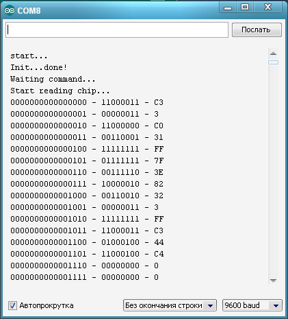
Record looks the same way. After clicking the Record button, the address and recording data are displayed in the port monitor.
I did not try to make a universal programmer, for different types of ROMs (although this is easy to do), I also did not try to make the firmware code optimal. The tasks of this shield are to read and write a ROM, and he copes with them.
As a power source for 25V, I used a universal power supply for a laptop. It provides voltages from 12 to 24 volts, with an incoming voltage of 12V or 110-220V. 24 V for recording was enough.
Arduino Mega is connected via USB to the computer. As part of the Arduino development environment has a utility - Port Monitor. It will display the entire process of the programmer.
The program code for writing to the ROM should be saved in the root folder of the SD card as code.hex.
After power on, the programmer offers to enter the command - Read or Write.
Example of reading data from the ROM (recorded Monitor)
Record looks the same way. After clicking the Record button, the address and recording data are displayed in the port monitor.
Source Code
#include <SD.h> int nMode = 0; //0- , 1-, 2- void WriteByte(int adr, int data){ int i; String sAdr, sData; // digitalWrite(42, LOW); pinMode(24, OUTPUT); pinMode(25, OUTPUT); pinMode(26, OUTPUT); pinMode(27, OUTPUT); pinMode(28, OUTPUT); pinMode(29, OUTPUT); pinMode(30, OUTPUT); pinMode(31, OUTPUT); // sAdr = ""; sData = ""; for (i = sizeof(adr) * 8 - 1; i >= 0; --i) { sAdr = sAdr + (String)((adr >> i) & 1); } for (i = sizeof(data) * 8 - 1; i >= 0; --i) { sData = sData + (String)((data >> i) & 1); } // if (sAdr.substring(15) == "1") digitalWrite(39, HIGH); else digitalWrite(39, LOW); if (sAdr.substring(14, 15) == "1") digitalWrite(38, HIGH); else digitalWrite(38, LOW); if (sAdr.substring(13, 14) == "1") digitalWrite(37, HIGH); else digitalWrite(37, LOW); if (sAdr.substring(12, 13) == "1") digitalWrite(36, HIGH); else digitalWrite(36, LOW); if (sAdr.substring(11, 12) == "1") digitalWrite(35, HIGH); else digitalWrite(35, LOW); if (sAdr.substring(10, 11) == "1") digitalWrite(34, HIGH); else digitalWrite(34, LOW); if (sAdr.substring(9, 10) == "1") digitalWrite(33, HIGH); else digitalWrite(33, LOW); if (sAdr.substring(8, 9) == "1") digitalWrite(32, HIGH); else digitalWrite(32, LOW); if (sAdr.substring(7, 8) == "1") digitalWrite(43, HIGH); else digitalWrite(43, LOW); if (sAdr.substring(6, 7) == "1") digitalWrite(41, HIGH); else digitalWrite(41, LOW); if (sAdr.substring(5, 6) == "1") digitalWrite(40, HIGH); else digitalWrite(40, LOW); // if (sData.substring(15) == "1") digitalWrite(24, HIGH); else digitalWrite(24, LOW); if (sData.substring(14, 15) == "1") digitalWrite(25, HIGH); else digitalWrite(25, LOW); if (sData.substring(13, 14) == "1") digitalWrite(26, HIGH); else digitalWrite(26, LOW); if (sData.substring(12, 13) == "1") digitalWrite(27, HIGH); else digitalWrite(27, LOW); if (sData.substring(11, 12) == "1") digitalWrite(28, HIGH); else digitalWrite(28, LOW); if (sData.substring(10, 11) == "1") digitalWrite(29, HIGH); else digitalWrite(29, LOW); if (sData.substring(9, 10) == "1") digitalWrite(30, HIGH); else digitalWrite(30, LOW); if (sData.substring(8, 9) == "1") digitalWrite(31, HIGH); else digitalWrite(31, LOW); // 10 delay(10); // digitalWrite(42, HIGH); digitalWrite(44, HIGH); delay(60); // 60 digitalWrite(44, LOW); digitalWrite(42, LOW); } void writeChip() { nMode = 0; int adr, dat; adr = 0; // File myFile = SD.open("code.hex"); if (myFile) { // : while (adr < 2048 && myFile.available()) { dat = myFile.read(); Serial.print((String)adr+" - "+(String)dat+" - "); Serial.println(dat, HEX); WriteByte(adr, dat); adr++; } // : myFile.close(); } else { // , : Serial.println("No file code.hex found!!!"); } } void readChip() { int r, i, adr = 0; String sAdr, sData; // digitalWrite(42, LOW); pinMode(24, INPUT); pinMode(25, INPUT); pinMode(26, INPUT); pinMode(27, INPUT); pinMode(28, INPUT); pinMode(29, INPUT); pinMode(30, INPUT); pinMode(31, INPUT); adr = 0; while (adr < 2048) { // sAdr = ""; sData = ""; for (i = sizeof(adr) * 8 - 1; i >= 0; --i) { sAdr = sAdr + (String)((adr >> i) & 1); } // if (sAdr.substring(15) == "1") digitalWrite(39, HIGH); else digitalWrite(39, LOW); if (sAdr.substring(14, 15) == "1") digitalWrite(38, HIGH); else digitalWrite(38, LOW); if (sAdr.substring(13, 14) == "1") digitalWrite(37, HIGH); else digitalWrite(37, LOW); if (sAdr.substring(12, 13) == "1") digitalWrite(36, HIGH); else digitalWrite(36, LOW); if (sAdr.substring(11, 12) == "1") digitalWrite(35, HIGH); else digitalWrite(35, LOW); if (sAdr.substring(10, 11) == "1") digitalWrite(34, HIGH); else digitalWrite(34, LOW); if (sAdr.substring(9, 10) == "1") digitalWrite(33, HIGH); else digitalWrite(33, LOW); if (sAdr.substring(8, 9) == "1") digitalWrite(32, HIGH); else digitalWrite(32, LOW); if (sAdr.substring(7, 8) == "1") digitalWrite(43, HIGH); else digitalWrite(43, LOW); if (sAdr.substring(6, 7) == "1") digitalWrite(41, HIGH); else digitalWrite(41, LOW); if (sAdr.substring(5, 6) == "1") digitalWrite(40, HIGH); else digitalWrite(40, LOW); // 10 delay(10); r = 0; if (digitalRead(24) == HIGH){ sData = "1" + sData; r = r + pow(2, 0); } else sData = "0" + sData; if (digitalRead(25) == HIGH){ sData = "1" + sData; r = r + pow(2, 1); } else sData = "0" + sData; if (digitalRead(26) == HIGH){ sData = "1" + sData; r = r + pow(2, 2); } else sData = "0" + sData; if (digitalRead(27) == HIGH){ sData = "1" + sData; r = r + pow(2, 3); } else sData = "0" + sData; if (digitalRead(28) == HIGH){ sData = "1" + sData; r = r + pow(2, 4); } else sData = "0" + sData; if (digitalRead(29) == HIGH){ sData = "1" + sData; r = r + pow(2, 5); } else sData = "0" + sData; if (digitalRead(30) == HIGH){ sData = "1" + sData; r = r + pow(2, 6); } else sData = "0" + sData; if (digitalRead(31) == HIGH){ sData = "1" + sData; r = r + pow(2, 7); } else sData = "0" + sData; Serial.print(sAdr+" - "); Serial.print(sData+" - "); Serial.println(r, HEX); adr++; } nMode = 0; } void setup() { nMode = 0; Serial.begin(9600); pinMode(4, INPUT); pinMode(5, INPUT); pinMode(53, OUTPUT); if (!SD.begin(53)) { Serial.println("Card failed, or not present"); return; } Serial.println("start..."); pinMode(44, OUTPUT); digitalWrite(44, LOW); pinMode(42, OUTPUT); digitalWrite(42, LOW); pinMode(39, OUTPUT); pinMode(38, OUTPUT); pinMode(37, OUTPUT); pinMode(36, OUTPUT); pinMode(35, OUTPUT); pinMode(34, OUTPUT); pinMode(33, OUTPUT); pinMode(32, OUTPUT); pinMode(43, OUTPUT); pinMode(41, OUTPUT); pinMode(40, OUTPUT); Serial.println("Init...done!"); Serial.println("Waiting command..."); } void loop() { if (digitalRead(4) == LOW && nMode == 0){ delay(20); // if (digitalRead(4) == LOW && nMode == 0){ Serial.println("Start writing chip..."); nMode = 2; writeChip(); Serial.println("Writing complete!!!"); delay(5000); } } if (digitalRead(5) == LOW && nMode == 0){ delay(20); // if (digitalRead(5) == LOW && nMode == 0){ Serial.println("Start reading chip..."); nMode = 1; readChip(); Serial.println("Reading complete!!!"); delay(5000); } } delay(100); } Source: https://habr.com/ru/post/247211/
All Articles