Risen from the dead (review of target installations umus-127)
In this article I want to tell you about the working machines, which for the past 30 years have been helping to train soldiers in shooting business.
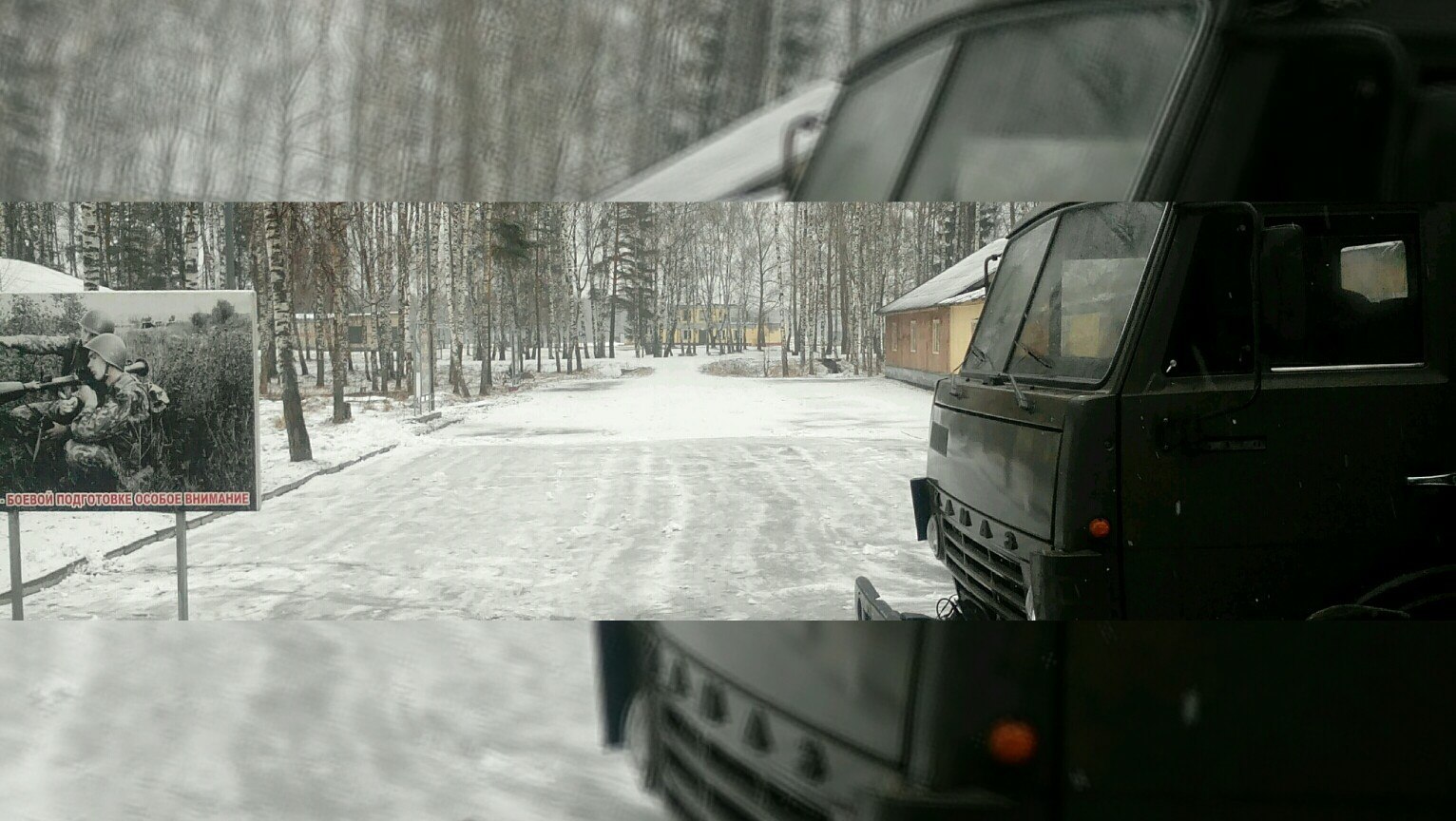
It will be about equipping the shooting range of the army range.
Interested please under the cat

under the cut photo
')
And hello again Habr!
So it was my destiny-fate that I had to change my place of work, and with it my place of residence, well, for the sake of completeness, the hairstyle, mode of the day, clothes and so on ... in short, they took me to the army!
Great round, well, a bunch of prof. The tests identified me at the "landfill" as an electrician-operator.
It was then that I became acquainted with such devices as target installations (mind-s-127 / mind-t-127)
Technical data of UMU-S-127.
Target lifting time - no more than 4 s
Target lowering time - no more than 4 s
Installation Management - Local, Remote
Power supply - 127 V
Power frequency - 50 Hz
Power consumption - no more than 250 VA
Electric motor - UL-042M
Power - 60 W
Rotational speed - 8000 rpm
Parameters of light simulation of small arms fire:
the frequency of flash bulbs - 3 + 1 Hz;
pause between series of flashes - 5 + 1 Hz
simulation duration - 3 + 1 Hz
Parameters of light imitation of artillery fire:
duration of imitation (“shot”) - 3 + 1 Hz
pause between “shots” - 5 + 1 Hz
Duration of the target signal:
in the PDD mode, the hit score is 2 + 1 s
in UPS mode - continuously until the “UNLOCK” command is issued
Applicable sensors - inertial, lining.
Resistance between the plates of the target - not less than 300 Ohms
I will say right away - I was not particularly lucky with my “object” ...
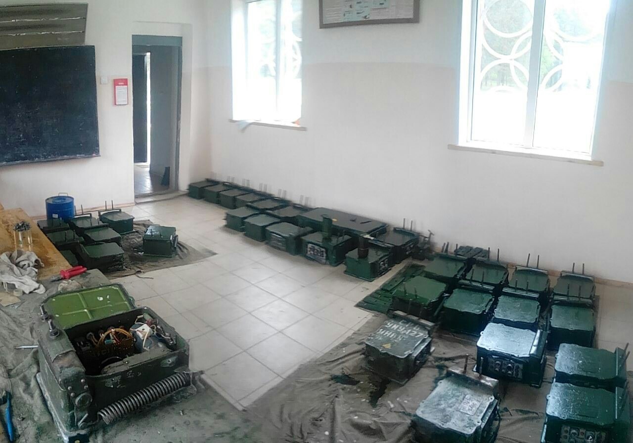
in my shooting range it was almost abandoned, and more correctly to say - a neglected field with broken lines, 20 out of 60+ working installations and very heavy loads in terms of ensuring shooting ...
These installations are designed for lifting heavy, medium and light (by weight) targets, at shooting ranges, directresses and firing camps when training troops firing at emerging targets (tanks, armored personnel carriers, vehicles, anti-tank guns, infantry, etc.)


At targets fixed in the target-holders of installations, it is possible to conduct shooting from small tank weapons, artillery systems with a supplementary stem, as well as firing a regular projectile in inert equipment.
Installations provide:
- lifting targets
- omission of a target (both at defeat, and when giving a command from the control panel)
- repeated display of not hit targets when giving the command from the control panel
- the issuance of signals of light imitation of shooting small arms, artillery and the work of an infrared searchlight.
- illumination of the target when shooting at night.
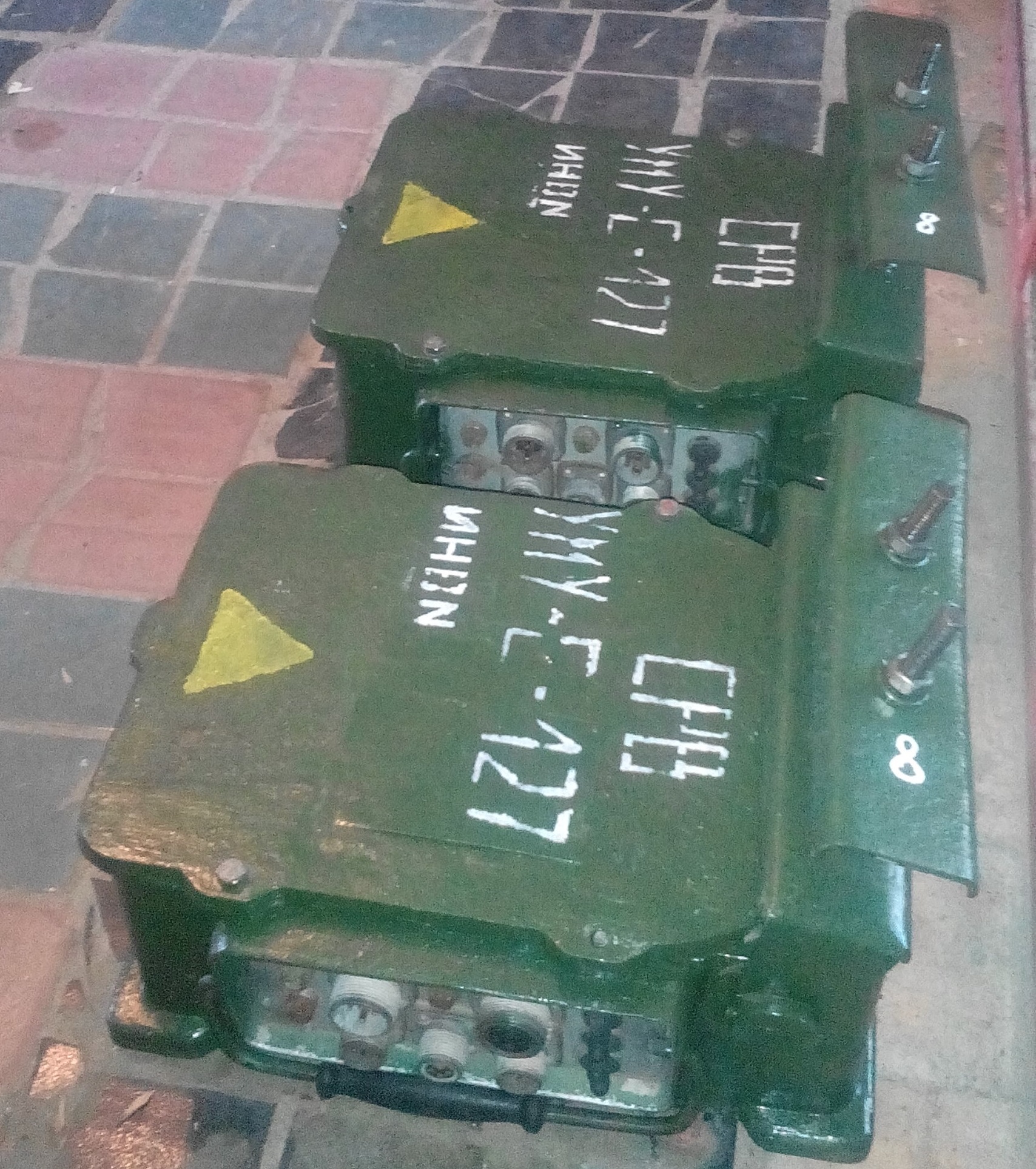
Well, let's begin our acquaintance with the lift closer,
From itself it is a molded case, on one of the faces of which are located connectors for connecting the installation in the field.
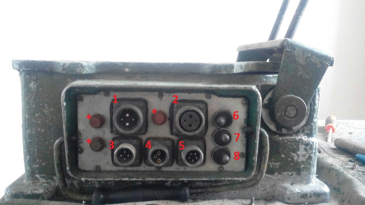
Connectors 1 and 2 are for power supply ~ 127v. and they are paralleled for easy connection (in the field there can be both “mom” and “dad”)
Connector 3 is designed to connect sensors that are mounted on the target (they are of two types, inertial and covering, but more on that later)
Connector 4 is required for feedback with the target field control panel.
Connector 5- to connect to the installation of target lighting
Chicken ass stars marked fuses on the board \ engine \ feedback information
Tumbler on the right side is responsible for managing the installation (local and remote modes, switching modes of simulation and account)

The electromechanical drive of the installation consists of:
- Reducer 1 ,
electric motor with brake 2
- crank mechanism 3 .
- Management of the elevator is carried out using the electrical unit BMU.127 4
.
So, how does this whole thing work?
The electric motor through the flange is connected to the brake housing, and the shaft through the cross coupling is connected to the drive shaft of the gearbox.
Electromagnetic disc brake of permanently closed type is mounted on the gearbox drive shaft.
The three-stage spur gear has a total gear ratio of 505 (this is on the UMUS-127 light elevator, and there is also UMUT-127, there will be more of this number) . On the output shaft of the gearbox, there is a cam, which is the driving link of the four-joint hinge that converts the rotational movement of the output shaft of the gearbox into a swinging movement of the rocker arm sitting on the lift shaft via a thrust rod. Half a turn of a cam, the steering shaft turns
at an angle of 83.6 degrees. Acting on themicroswitch limit switch , the cam switches off the electric motor in the final positions of the target.
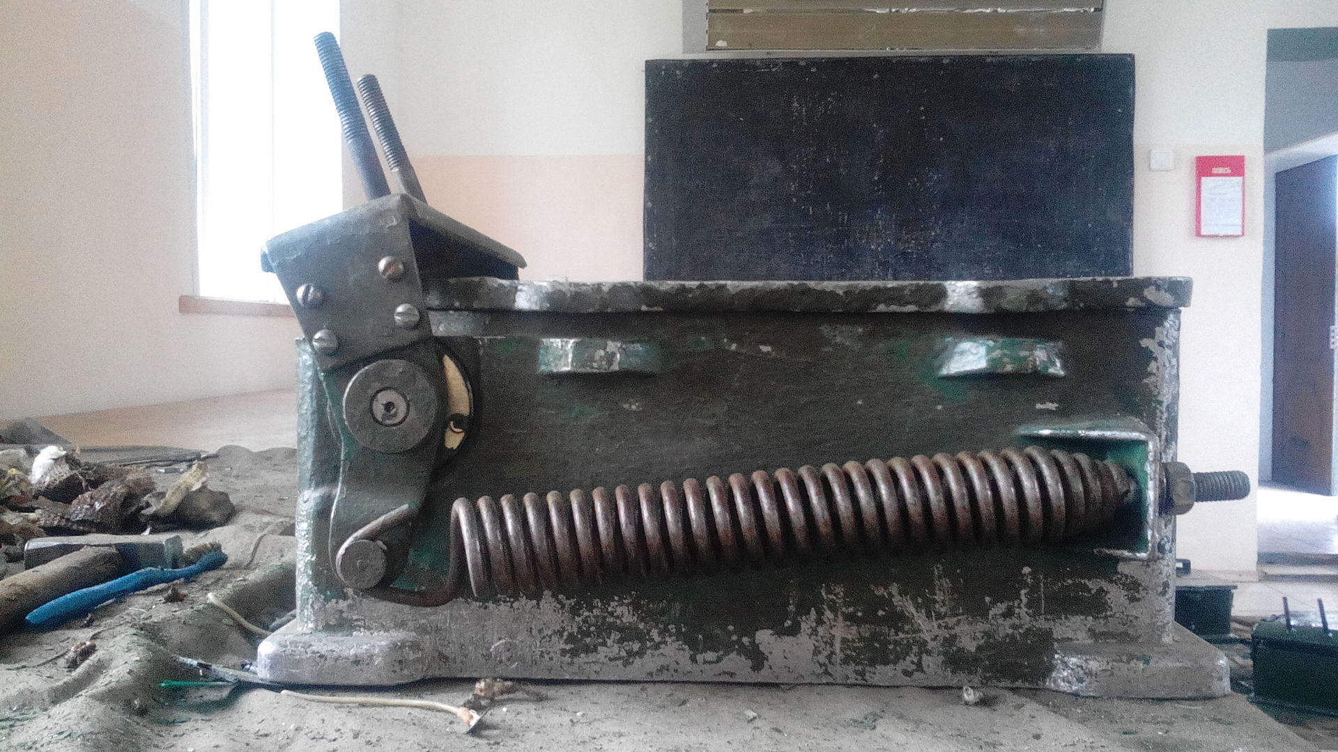
On the reverse side of the installationmoon , there is only a spring, which, storing energy when the target is lowered, gives it away during
lifting.
The “brains” of this thing are the electrical unit BMU-127, which is a chassis on which are mounted: a transformer, a connector block for connecting to a target unit and a printing unit.
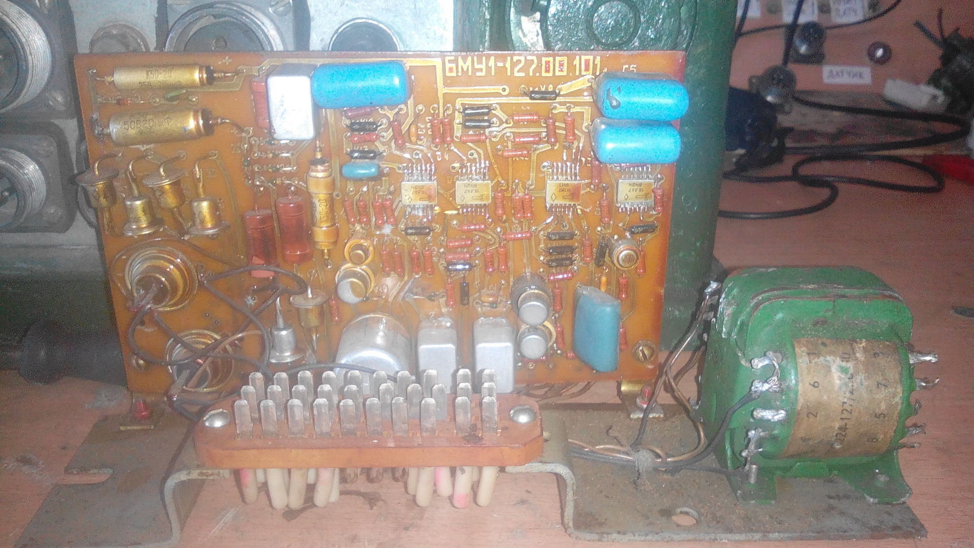
The schematic diagram of this block is the following:

So. What can he ask you?
And I will tell you what tobreak) it can determine if a target is hit (a bullet’s passage through a target or vibrations / vibrations from being hit, this depends on the type of sensor connected to the installation), drop the target when hit and send information to the operator’s console, or read hits that will also be displayed on the remote)
Simulate using backlight automatic and single shots, well, or just light the target.
So ... what else haven't you talked about?
oh yeah ... sensors ... They are of two types, covering and inertial

This inertial sensor is a device with two normally closed
contacts that are enclosed in a plastic case.
The principle of its operation is as follows:
When the bullet hits the target shield, the contacts from shaking open. The sensitivity of the sensor is regulated by a special screw on
sensor housing. The sensor is simple, funny, but alas, not very practical.
The fact is that it works practically from everything if it is configured, and even if it is configured, the chance of an accidental operation is extremely high. Any ricochet, the oscillation of the target from the wind (and imagine if the target is a tank with dimensions 2.8x2.3m) the windage of this thing - be healthy)
A lining sensor is essentially two wires connected to two sides of a target, and it responds to the closure of a bullet as it passes through it. As a rule, the target is made “sandwich” tin / plywood / tin.
From its advantages, simplicity and “reliability” can be noted ... yes, let's call it precisely reliability) this type of sensors allows you to get rid of ricochets, get rid of the chore of setting inertial sensors, and in general ... what could be simpler than two wires attached to a tee?) )
and lastly hell for a perfectionist)
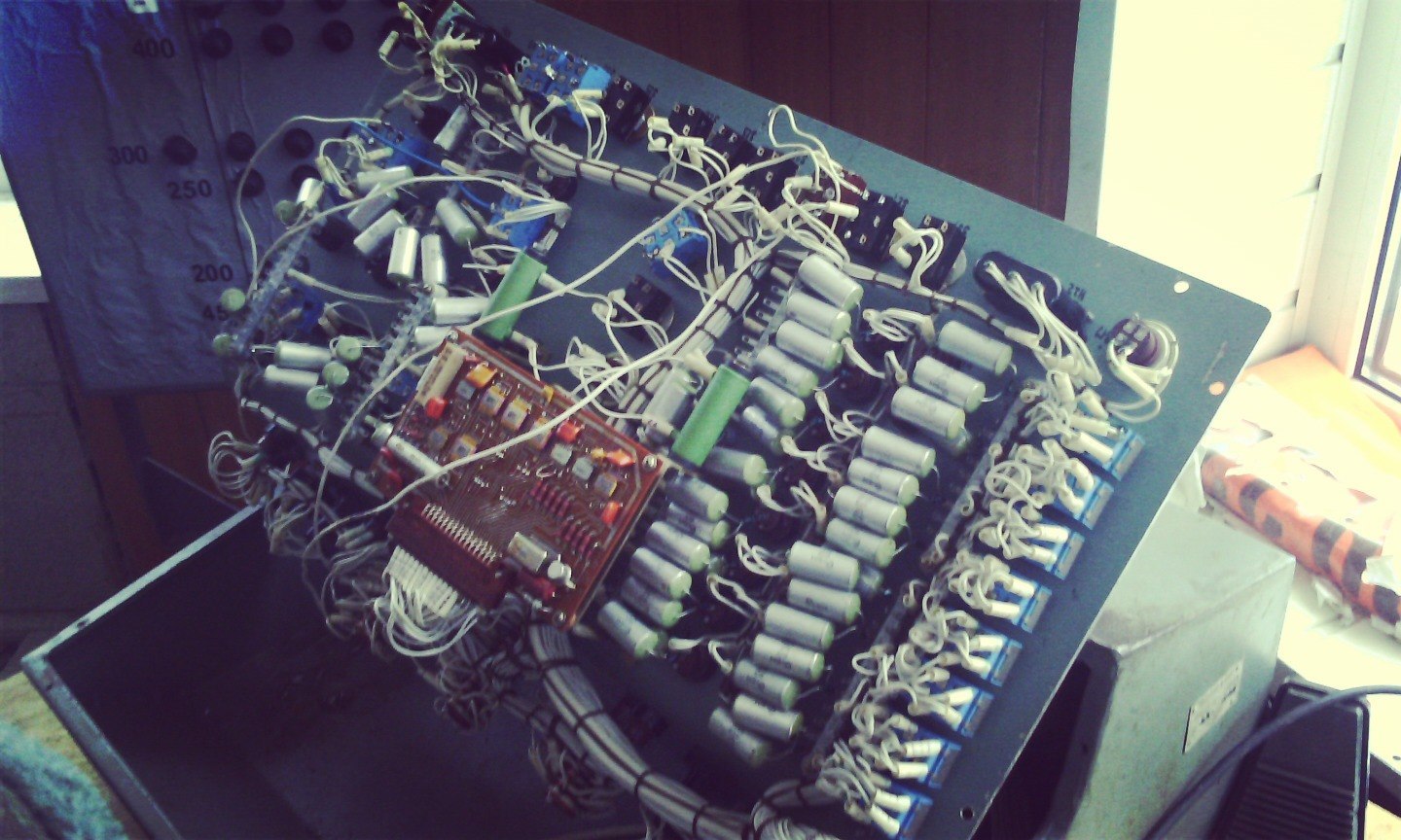
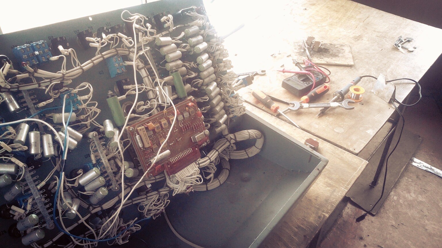

In the photos the filling of the console, from which the whole thing is managed.
and more amusing ...
because of the age of all these “devices”, they are already tired ... both morally and physically, so often especially in the morning, they wonderfully pierced the unpretentious operator who decided to serve them with the field turned on
alas, this is all ...
over time, I will try to supplement the article with new data and illustrations.
In the future, I hope to consecrate other types of lifts (heavy, radio-controlled, etc.),
I will be glad to your advice, comments and suggestions.
peace for everyone!
It will be about equipping the shooting range of the army range.
Interested please under the cat
under the cut photo
')
And hello again Habr!
So it was my destiny-fate that I had to change my place of work, and with it my place of residence, well, for the sake of completeness, the hairstyle, mode of the day, clothes and so on ... in short, they took me to the army!
Great round, well, a bunch of prof. The tests identified me at the "landfill" as an electrician-operator.
It was then that I became acquainted with such devices as target installations (mind-s-127 / mind-t-127)
Technical data of UMU-S-127.
Target lifting time - no more than 4 s
Target lowering time - no more than 4 s
Installation Management - Local, Remote
Power supply - 127 V
Power frequency - 50 Hz
Power consumption - no more than 250 VA
Electric motor - UL-042M
Power - 60 W
Rotational speed - 8000 rpm
Parameters of light simulation of small arms fire:
the frequency of flash bulbs - 3 + 1 Hz;
pause between series of flashes - 5 + 1 Hz
simulation duration - 3 + 1 Hz
Parameters of light imitation of artillery fire:
duration of imitation (“shot”) - 3 + 1 Hz
pause between “shots” - 5 + 1 Hz
Duration of the target signal:
in the PDD mode, the hit score is 2 + 1 s
in UPS mode - continuously until the “UNLOCK” command is issued
Applicable sensors - inertial, lining.
Resistance between the plates of the target - not less than 300 Ohms
I will say right away - I was not particularly lucky with my “object” ...
in my shooting range it was almost abandoned, and more correctly to say - a neglected field with broken lines, 20 out of 60+ working installations and very heavy loads in terms of ensuring shooting ...
These installations are designed for lifting heavy, medium and light (by weight) targets, at shooting ranges, directresses and firing camps when training troops firing at emerging targets (tanks, armored personnel carriers, vehicles, anti-tank guns, infantry, etc.)
At targets fixed in the target-holders of installations, it is possible to conduct shooting from small tank weapons, artillery systems with a supplementary stem, as well as firing a regular projectile in inert equipment.
Installations provide:
- lifting targets
- omission of a target (both at defeat, and when giving a command from the control panel)
- repeated display of not hit targets when giving the command from the control panel
- the issuance of signals of light imitation of shooting small arms, artillery and the work of an infrared searchlight.
- illumination of the target when shooting at night.
Well, let's begin our acquaintance with the lift closer,
From itself it is a molded case, on one of the faces of which are located connectors for connecting the installation in the field.
Connectors 1 and 2 are for power supply ~ 127v. and they are paralleled for easy connection (in the field there can be both “mom” and “dad”)
Connector 3 is designed to connect sensors that are mounted on the target (they are of two types, inertial and covering, but more on that later)
Connector 4 is required for feedback with the target field control panel.
Connector 5- to connect to the installation of target lighting
Tumbler on the right side is responsible for managing the installation (local and remote modes, switching modes of simulation and account)
The electromechanical drive of the installation consists of:
- Reducer 1 ,
electric motor with brake 2
- crank mechanism 3 .
- Management of the elevator is carried out using the electrical unit BMU.127 4
.
So, how does this whole thing work?
The electric motor through the flange is connected to the brake housing, and the shaft through the cross coupling is connected to the drive shaft of the gearbox.
Electromagnetic disc brake of permanently closed type is mounted on the gearbox drive shaft.
The three-stage spur gear has a total gear ratio of 505 (this is on the UMUS-127 light elevator, and there is also UMUT-127, there will be more of this number) . On the output shaft of the gearbox, there is a cam, which is the driving link of the four-joint hinge that converts the rotational movement of the output shaft of the gearbox into a swinging movement of the rocker arm sitting on the lift shaft via a thrust rod. Half a turn of a cam, the steering shaft turns
at an angle of 83.6 degrees. Acting on the
On the reverse side of the installation
lifting.
The “brains” of this thing are the electrical unit BMU-127, which is a chassis on which are mounted: a transformer, a connector block for connecting to a target unit and a printing unit.
The schematic diagram of this block is the following:
So. What can he ask you?
And I will tell you what to
Simulate using backlight automatic and single shots, well, or just light the target.
So ... what else haven't you talked about?
oh yeah ... sensors ... They are of two types, covering and inertial
This inertial sensor is a device with two normally closed
contacts that are enclosed in a plastic case.
The principle of its operation is as follows:
When the bullet hits the target shield, the contacts from shaking open. The sensitivity of the sensor is regulated by a special screw on
sensor housing. The sensor is simple, funny, but alas, not very practical.
The fact is that it works practically from everything if it is configured, and even if it is configured, the chance of an accidental operation is extremely high. Any ricochet, the oscillation of the target from the wind (and imagine if the target is a tank with dimensions 2.8x2.3m) the windage of this thing - be healthy)
A lining sensor is essentially two wires connected to two sides of a target, and it responds to the closure of a bullet as it passes through it. As a rule, the target is made “sandwich” tin / plywood / tin.
From its advantages, simplicity and “reliability” can be noted ... yes, let's call it precisely reliability) this type of sensors allows you to get rid of ricochets, get rid of the chore of setting inertial sensors, and in general ... what could be simpler than two wires attached to a tee?) )
and lastly hell for a perfectionist)
In the photos the filling of the console, from which the whole thing is managed.
and more amusing ...
because of the age of all these “devices”, they are already tired ... both morally and physically, so often especially in the morning, they wonderfully pierced the unpretentious operator who decided to serve them with the field turned on
operator's alarm clock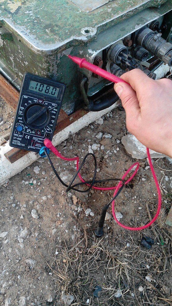
alas, this is all ...
over time, I will try to supplement the article with new data and illustrations.
In the future, I hope to consecrate other types of lifts (heavy, radio-controlled, etc.),
I will be glad to your advice, comments and suggestions.
peace for everyone!
Source: https://habr.com/ru/post/247135/
All Articles