Networks for the smallest. Part ten. Basic MPLS
The network of our imaginary company linkmeup is growing. She already has trunk lines in various cities, a client base and an excellent staff of engineers who grew up on the SDTSM cycle.
But they are not enough. BBA services are good and necessary, but there is still a huge potential market for corporate customers who need a VPN.
The guys thought about it, puzzled and came to the conclusion that there is no way to do without MPLS.
If the multicast was the first topic that required some rebuilding of the understanding of IP networks, then while studying MPLS, you definitely have to forget almost everything that you knew before - this is a special world with its own rules.

')
Today in issue:
And we start with the question: "What is wrong with IP?"
Traditional video
And really, what's wrong? Why fence MPLS?
Yes, everything is so. The advantages and disadvantages of IP derive from the fact that it appeared later than classic networks and is incredibly flexible. Nowadays, there is a transition to packet switching, which is based on IP at the network level, and Ethernet is gaining more and more popularity on the channel link.
This is good, because now, on the basis of one backbone network and access network, you can provide broadband access , IP-telephony, IPTV and other possible services.
The same can be seen in the networks of mobile operators. The network of the second generation at the dawn were entirely on the basis of circuit switching . The core of 3G networks is for the most part IP, but telephony services can still be provided in circuit-switched mode. 4G networks are already full-fledged IP networks, where voice transmission is only one of the applications, as well as broadband access.
However, there is still a huge number of segments that use old technology. For example, somewhere there is ATM, in another place you need to transfer PDH from one part of the network to another, and then the client wanted his piece of Ethernet-network to be accessible from the other end of the city as if he was connected directly - in other words VPN.
As it was solved before: you need an ATM between two geographic points - build a channel between them based on ATM, PDH - build PDH.
And you want to do all this through one network, and not to build a separate one for each type of traffic.
For this, GRE, PPPoE, PPPoA, ATM over Ethernet, TDM over IP, and numerous other over'y were invented at one time. You can create another thousand others to cover all the combinations, and universal happiness will come in the chaos of standards ( by the way, some small manufacturers have gone this way ).
In the mid-90s, hotheads from several companies (IBM, Toshiba, Cisco, Ipsilon) came up with the idea of creating a mechanism for routing not looking inside the package and combining the routing table in search of a better way, but to be guided by a certain label. Shot from Cisco, and the mechanism was called plain: TAG Switching.
Moreover, the goal pursued by the developers was to allow high-speed switches to transmit traffic exclusively in hardware. The fact is that hardware IP routing has been an inaccessible pleasure for a long time, and it was impractical to use it on low-cost switches, and making decisions based on the label could be simple and fast.
But at the same time, super-large-scale integrated circuits have appeared (even if I do not agree with this term - the English VLSI describes the essence much better), and the task of saving on analyzing the contents of the package was not so relevant. In addition, the concept of FIB appeared, which assumes that for each packet it is not necessary to search for a destination in the routing table and accordingly involve the central processor - all hot information is already on the line card.
That is, in essence, the need for such a mechanism has disappeared.
But suddenly it became clear that label switching has unplanned potential - it doesn’t matter what is under the label - IP, Ethernet, ATM, Frame Relay. It also gives you the opportunity to get rid of the limitations of IP routing.
Hence the technology approved by IETF - MPLS - MultiProtocol Label Switching. It was the year 1997.
And this, seemingly insignificant, detail gave rise to a new era in telecommunications. Today MPLS can be found in any more or less large provider.
Main MPLS applications now:
We will talk about each of them in separate articles - these are monstrously huge topics. But we will briefly touch them at the end of the article.
By itself, pure MPLS is rarely used. The performance gain is insignificant, because the difference between looking at the FIB / changing some fields in the headers and seeing the table of labels / changing the label in the MPLS header is not that big. Of course, its applications listed above are used.
But in this article we will concentrate on pure MPLS, in order to understand how it works in its most basic form.
Below we will also consider one application of pure MPLS.
Despite the fact that MPLS is not tied to the type of network on which it will work, in our time it lives in symbiosis only with IP. That is, the network itself is built on top of IP, but at the same time it can transfer data from many other protocols.
But let's get to the point, and first I want to say that MPLS does not replace IP routing , but works on top of it.
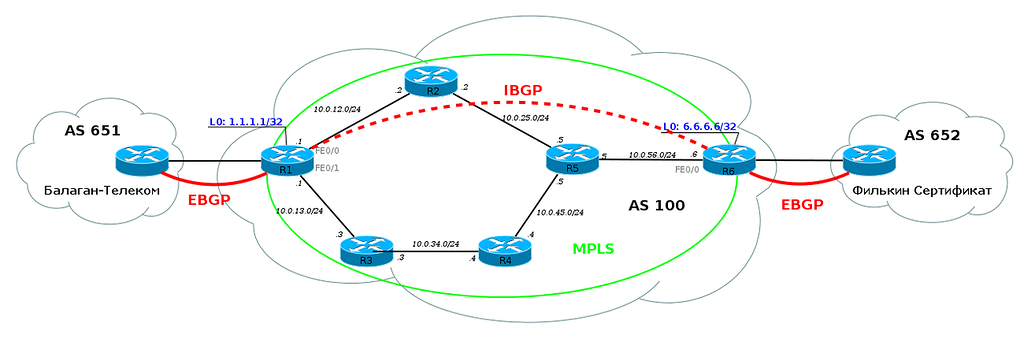
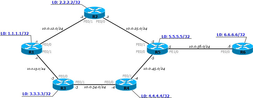
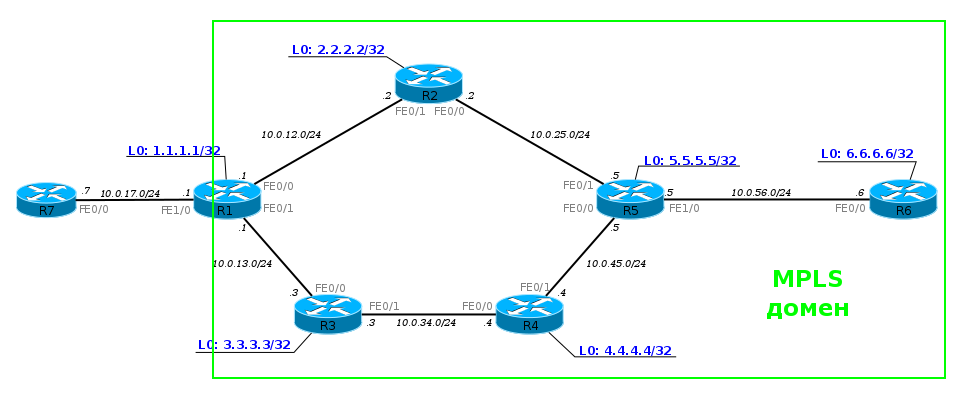
To be more specific, I will take such a network.

Now it is fully operational, but without any hint of MPLS. That is, R1, for example, sees R6 and can ping it with Loopback.
PC1 sends an ICMP request to server 172.16.0.2. An ICMP request is an IP packet. On R1, according to the basic principles, the packet goes through the FE0 / 0 interface on R2 - the Routing Table said so.
R2, after receiving the packet, checks the destination address, looks at its FIB, sees the next router and sends the packet to the FE0 / 0 interface.
And this process is repeated time after time. Each router independently decides the fate of the packet.
This is how a traffic dump looks quite familiar:

What happens if we activate MPLS? Immediately, at the same second the world changes. After that, the label tables are filled in on routers and numerous LSPs are built.
And now the same path will be done a little differently.
When an IP packet from PC1 enters the MPLS network, the first router hangs a label, then this packet goes to the destination point, and each next router changes one label to another. When you exit the MPLS network, the label is removed and the already clear IP packet is transmitted as it was at the very beginning.
This is the basic principle of MPLS - routers switch packets by tags without looking inside the MPLS packet. The first one adds, the last one deletes.
Let us consider, step by step, the transfer of a data packet from PC1 to the destination node:
1. PC1 - a normal computer - sends a normal package to a remote server.
2. The package reaches R1. It adds label 18. It is inserted between the IP header and Ethernet.
This information can be obtained from the FIB:
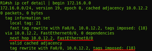
The FIB shows that the packet with the addressee 6.6.6.6 needs to be labeled 18 and sent to the interface FE0 / 0 .
Actually, this is what he does: he adds the heading and writes 18 to it:
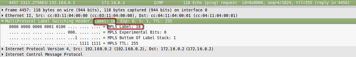
Dump between R1 and R2 .
3. R2 receives this packet, sees in the Ethernet header that it is an MPLS packet (Ethertype 8847), reads the label and refers to its tag table:
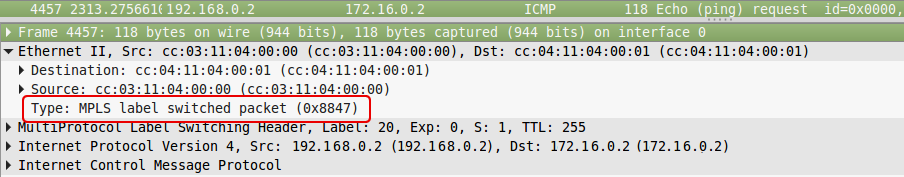
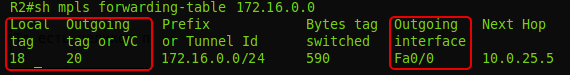
We read the letters: if the MPLS packet came with a mark of 18, you need to change it to 20 and send the packet to the FE0 / 0 interface.
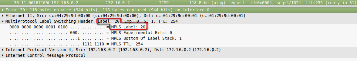
Dump after R2.
4. R5 performs similar actions - sees that a packet with a label of 20 has arrived, it needs to be changed to 0 and sent to FE1 / 0. Without any access to the routing table.
5. R6, having received the MPLS package, sees in its table that the label must now be removed. And, having removed it, he already sees that the recipient of the packet - 172.16.0.2 - is a Directly Connected network. Next, the packet is transmitted in the usual way by the routing table already without any tags.
We will not consider the end nodes in order not to complicate the scheme.
So far, it seems, everything is simple, even if it is not clear why.
Now the IGP and MPLS domains are the same, and MPLS only promises to us in the future some kind of buns: L2VPN, L3VPN, MPLS TE.
But, in fact, even basic MPLS gives us advantages if we remember that we are a provider.
As a provider, we do not use IGP protocols for routing between ASs. For this we use BGP. And it is in conjunction with BGP that the benefits of MPLS will become clear.
Consider our network in conjunction with neighboring AS:
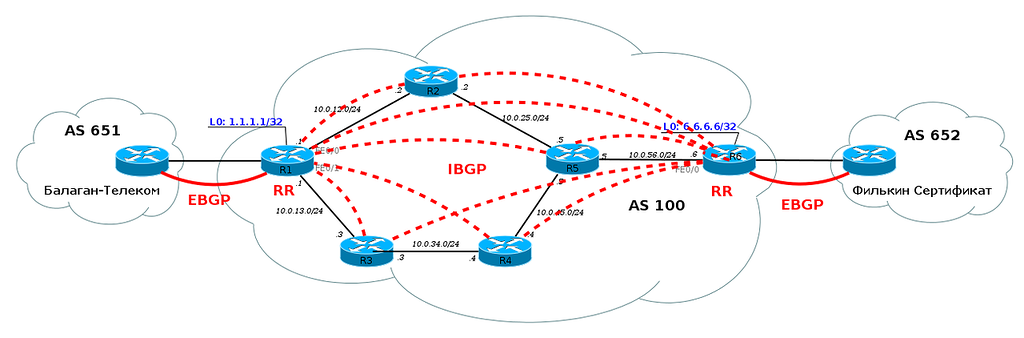
From the BGP release, we know that BGP must be configured on every router in our AS. Otherwise we will not be able to transfer traffic from neighboring AS and our customers through our AS. Each router must know all routes.
But that was before MPLS!
When MPLS is configured on our network, we no longer have to configure BGP on every router on the network. It is enough to configure it only on border routers in the AS, on those that are connected to other clients or providers.
But this is not all good news. In addition to the fact that BGP can now not be configured on each router in the AS, routers also do not need to create a label for each BGP prefix. It is enough to know how to get to the IP address, which is listed as next-hop. That is, if the BGP session is configured between Loopback0 R1 and Loopback0 R6, then nothing changes in the table of labels, even if each of them sends hundreds of thousands of routes via BGP:
For example, several routes have come to router R1 via BGP from router R6:

Let's see how the packets that go to the network 100.0.0.0/16 will be processed:
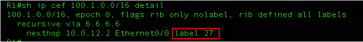
In the output above, it is clear that packets 27 will be added to the packets.
And, if you look at the table of labels, then there are no labels for routes that are known from BGP, but there is a label 27 and it corresponds to 6.6.6.6/32. And this is exactly the address that we saw in the routes that came on BGP from R6:

An example of the setting you can find below .
We ran a little ahead, but now that it has become clearer what advantages even basic MPLS gives, we can plunge into the conceptual apparatus in the world of MPLS.
Label - a label - a value from 0 to 1,048,575. Based on it, the LSR decides what to do with the package: which new label to hang, where to transfer it.
It is part of the MPLS header.
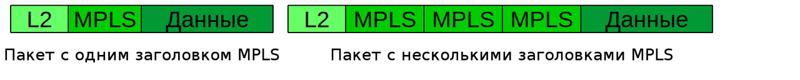
Label Stack - a stack of labels. Each package can carry one, two, three, but at least 10 tags - one above the other. The decision about what to do with the package is made on the basis of the upper tag. Each layer plays its own role.
For example, when transmitting a packet, a transport label is used, that is, a label that organizes transit from the first to the last MPLS router.
Others may carry information that this packet belongs to a particular VPN.
In this release there will always be only one label - more is not needed yet.
Push Label — the operation of adding a label to a data packet — is done at the very beginning — on the first router in the MPLS network (in our example, R1).
Swap Label - label replacement operation - occurs on intermediate routers in the MPLS network - the node receives a packet with one label, changes it and sends it with another (R2, R5).
Pop Label - label removal operation - performed by the last router - the node receives the MPLS packet and removes the top label before passing it on (R6).
LSR - Label Switch Router is any router in the MPLS network. It is called that because it performs some operations with labels. In our example, these are all nodes: R1, R2, R3, R4, R5, R6.
LSR is divided into 3 types:
Intermediate LSR - MPLS intermediate router - it performs the Swap Label operation (R2, R5).
Ingress LSR - “input”, the first MPLS router - it performs the Push Label (R1) operation.
Egress LSR is “output”, the last MPLS router is performing the Pop Label (R6) operation.
LER - Label Edge Router is a router at the edge of the MPLS network.
In particular, Ingress LSR and Egress LSR are boundary, which means they are also LER.
LSP - Label Switched Path - label switching path. This is a unidirectional channel from the Ingress LSR to the Egress LSR, that is, the path that the packet will actually go through the MPLS network. In other words, it is the LSR sequence.
It is important to understand that the LSP is in fact unidirectional. This means that, firstly, traffic is transmitted only in one direction, secondly, if there is “there”, it does not necessarily exist “back”, thirdly, “back” does not necessarily follow the same path, that "there". Well, it's like the tunnel interfaces in GRE.
What does LSP look like?
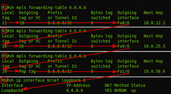
Yes, that's so unpredictable.
This is a compiled output from four LSRs - R1, R2, R5, R6. That is, on the LSR you will not see the complete sequence of nodes from the input to the output, according to the type of the AS-PATH attribute in BGP. Here, each node knows only the input and output labels. But the LSP does exist.
This looks a bit like IP routing. Despite the fact that there is a path from point A to point B, the routing table only knows the next node to send traffic to. But the difference is that the LSR does not decide on each packet based on the destination address — the path is determined in advance.
And one of the most important concepts that you need to understand - FEC - Forwarding Equivalence Class . For some reason it was very hard for me, although in fact everything is simple. FEC are traffic classes. In the simplest case, the class identifier is the destination address prefix (roughly speaking, the IP address or the destination subnet).
For example, there are traffic flows from different clients and different applications that go all to the same address — all these flows belong to the same class — one FEC — use the same LSP.
If we take other streams from other clients and applications to another destination address, this will be a different class and another LSP respectively.
If you pay attention to the label table, the FEC is there, since the label replacement parameters are determined just on the basis of the FEC, but this is done only at the first moment in time - when these labels are distributed. When real traffic is running on the LSP, no one except Ingress LSR looks at it — only labels and interfaces. Ingress LSR takes all the work to determine the FEC and in which LSP to send traffic - after receiving a clean packet, it analyzes it, checks which class it belongs to, and hangs the corresponding label. Packages of different FECs will receive different labels and will be sent to the appropriate interfaces.
Packages of the same FEC receive the same label.
That is, intermediate LSRs are threshers, which for all transit traffic only do the switching of tags. And all the intellectual work is done by Ingress LSR.
LIB - Label Information Base - a table of labels. Analogue of the routing table (RIB) in IP. It indicates for each input label, what to do with the package - change the label or remove it and which interface to send.
LFIB - Label Forwarding Information Base - by analogy with the FIB - this is the label base that the network processor refers to. When you receive a new package, there is no need to contact the CPU and lookup into the table of tags - everything is already at hand.
One of the initial ideas of MPLS - to maximize the spread of Control Plane and Data Plane - went into oblivion.
Developers wanted that when transmitting a packet through a router there was no analysis - just read the label, changed it to another one, transferred it to the correct interface.
To achieve this, there were just two separated processes - a relatively long construction of a path (Control Plane) and a fast transfer of traffic along this path (Data Plane)
But with the advent of cheap chips (ASIC, FPGA) and the FIB mechanism, the usual IP transmission also became fast and simple.
For the router, it doesn't matter where to look when sending a packet - in the FIB or in the LFIB.
But what is undoubtedly important and useful is that MPLS’s indifference to what is transmitted under its heading — IP, Ethernet, ATM. No need to fence GRE or any other uncomfortable VPNs before the pain in the joints. But let's talk more about this.
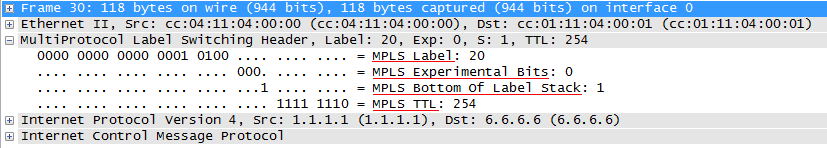
The entire MPLS header is 32 bits. The format of the fields and their length are fixed. Often the entire title is called a tag, although this is not entirely true.
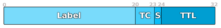
Label is the label itself. The length is 20 bits.
TC - Traffic Class. It carries the packet priority, as the DSCP field in IP.
Length 3 bits. That is, it can encode 8 different values.
For example, when an IP packet is transmitted over an MPLS network, the value in the DSCP field is definitely assigned the value of TC. Thus, a packet can be processed almost equally in queues all along its path, both on a pure IP site and in MPLS.
But, naturally, this is a lossy conversion — the six bits of the DSCP are closely in 3 bits of TC: 64 against 8. Therefore, there is a special correspondence table, where the whole range is just one value.
S — Bottom of Stack — 1 . MPLS , , MPLS, VPN. LSR . S «1», ( ) «0», ( ). LSR , , , — - . , , . , , , : MPLS - (IP, Ethernet, ATM, FR ).
, — , (LIFO — Last Input — First Output).
, , MPLS , — .
TTL — Time To Live — IP TTL . — 8 . — . IP- MPLS IP TTL MPLS TTL, . 255, IP IP TTL , .
, MPLS , — IP — . MPLS 2,5 , — Shim-header — -.
, MPLS. IETF, ATM, AAL5, Frame Relay.
:
As mentioned above, there may be 2 ^ 20 labels.
Some of them are reserved:
0 : IPv4 Explicit NULL Label . "Explicit empty label." It is used on the very last MPLS span - before the Egress LSR - in order to notify it that this 0 mark can be removed without looking at the tag table (more precisely LFIB).
For those FECs that originate locally (directly connected), Egress LSR selects label 0 and sends it to its neighbors — the penultimate LSR (Penultimate LSR).
When transmitting a data packet, the penultimate LSR changes the current label to 0.
When the Egress LSR receives a packet, it knows for sure that the top label just needs to be removed.
1 : Router Alert Label — Router Alert IP — , . , , , — , 1.
2 : IPv6 Explicit NULL Label — , 0, IP.
3 : Implicit Null . , MPLS Egress LSR. , MPLS . .
4-15 : .
Depending on the vendor, other tag values can be fixed, for example, on Huawei equipment, labels 16-1023 are used for static LSPs, and everything above is in dynamic ones. In Cisco, available tags start at the 16th.
In general, it became clear how traffic is transmitted and how MPLS tags are involved.
But tags are not taken from the bald - no one needs additional chaos on the eve of the New Year. Special protocols allocate labels between the Egress LSR and Ingress LSR, creating the LSP.
First, as you already understood, on some devices you can do everything manually - vivat diligence and diligence!
But in the era of automatic washing machines, there are three basic protocols for distributing tags - LDP, RSVP-TE and MBGP.
In short, the LDP - the easiest and most understandable way - is based on the routing information of the nodes. RSVP-TE is a development of the once-developed but unpopular RSVP protocol — it is used in MPLS-TE to build LSPs that meet certain conditions. IGP supporting Traffic Engineering (OSPF, ISIS) are necessary for its work.
MBGP is a close relative of BGP, but it’s a protocol from a slightly different story, it passes tags for other purposes. Therefore, it stands aside from the LDP and RSVP-TE.
Let's talk about each of them, but before that, a few words about how LSRs handle tags in general.
The first obvious fact is that the tags are distributed in the direction from the traffic receiver to the sender, and more precisely from the Egress LER to the Ingress LER. The first unobvious fact - in MPLS Downstream - is from the sender to the receiver, and Upstream from the receiver to the sender. For myself, I defined it this way: LSP “grows” from FEC up to Ingress LER, like a tree, and user traffic “goes down” to the recipient along the LSP, like rainwater along branches. That is, tags are distributed to meet traffic.
They also say that the LSP is built to meet traffic.
The very mechanism of distribution of tags depends on the protocol, settings and manufacturer.
First , the router can distribute tags to all its neighbors immediately and without unnecessary questions, and can issue it on request from the superiors (we remember, yes, which direction is called Upstream?)
The first mode is called DU - Downstream Unsolicited . As soon as the LSR learns about FEC, it sends tags to all its MPLS neighbors for this FEC.
It looks like this:
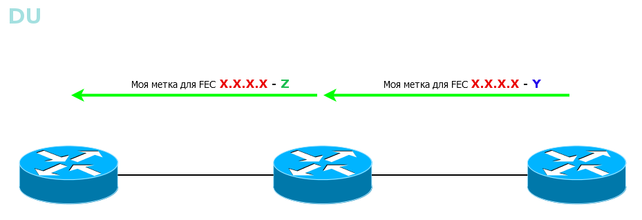
All LSRs will learn about all FECs in all possible ways. First, the FEC-tagging diverges across the entire network from neighbor to neighbor, almost as it does with the BootStrap messages in the PIM SM. And then each LSR chooses only the one that came along the best path, and uses it for the LSP - Reverse Path Forwarding in the same PIM SM works in the same way.
Quickly, simply, clearly, although it is not always necessary for everyone to know everything.
The second mode - DoD - Downstream-on-Demand . The LSR knows the FEC, it has neighbors, but until they ask what label is for this FEC, the LSR remains silent.
This method is convenient when some requirements are imposed on the LSP, for example, on the bandwidth. Why send a tag just like that if it is immediately dropped? Better, the superior LSR will ask the downstream: I need a label from you for this FEC - and that one is: “ok, on”.
The tag selection mode is interface specific and is determined at the time the connection is established. Both ways can be used on the network, but on the same line, neighbors should only agree on one specific one.
Second , the LSR can wait for the FEC label to come from the Egress LER side before telling its upstream neighbors. Or maybe send out tags for FEC as soon as I found out about him.
The first mode is called Ordered Control.
Ensures that by the time of data transfer all the way up to the output LER will be built.
The second mode is Independent Control .
That is, tags are transmitted in an irregular manner. Convenient in that traffic can begin to transmit even before the entire path is built. The same is dangerous.
Thirdly , it is important how the LSR handles the labels passed to it.
For example, in such a situation, should R1 store the information about tag 20 received from neighbor R3, which is not the best way to get to R6?

And this is determined by the label holding mode.
Liberal Label Retention Mode - tags are retained. In the case when R3 becomes the next step (for example, problems with the main route), the traffic will be redirected more quickly, because the label is already there. That is, the reaction rate is higher, but the number of tags used is also large.
Conservative Label Retention Mode - an extra label is discarded as soon as it is received. This reduces the number of tags used, but MPLS will respond more slowly in the event of an accident.
No, this is not the PHP you thought of. It's about Penultimate Hop Popping . All the engineers are a little optimizers, and here the guys thought: why should we process the MPLS headers twice - first on the penultimate router, then on the output one.
And they decided that the label should be removed on the penultimate LSR and called this action - PHP.
For PHP there is a special label - 3.
Returning to our example, for FEC 6.6.6.6 and 172.16.0.2 R6 allocates label 3 and reports it to R5.
When sending a packet to R6, R5 should assign it a dummy tag - 3, but in fact it does not apply and a bare IP packet is sent to the interface (note that PHP only works on IP networks) - that is, the Pop Label procedure was performed on R5 .
Let's follow the life of the package, taking into account everything that we now know.
With how traffic is transmitted, it seems, more or less clear. But who performs all the titanic work on creating labels, filling in tables?
There are not so many of them - three: LDP, RSVP-TE, MBGP.
There are two global goals - the distribution of transport marks and the distribution of service tags.
Explain that transport labels are used to transmit traffic over an MPLS network. These are the ones we are talking about the whole issue. LDP and RSVP-TE are used for them.
Service tags are used to separate different services. This is where MBGP and the LDP process - tLDP come into the arena.
In particular, MBGP allows, for example, to mark that such a route belongs to such a VPN. Then he sends this route as a vpn-ipv4 family to his neighbor with a tag, so that he can then separate the flies from the chops.
So, so that he could separate, and he needs to report on compliance label-FEC.
But this is the action of another play, which we will play in another six months or a year.
A prerequisite for the operation of all dynamic label distribution protocols is the basic setting of IP connectivity. That is, the network must be running IGP.
Well, now, when I have completely confused you, you can begin to unravel.
So what is the easiest way to distribute tags? The answer is to enable LDP.
The protocol with a very transparent name - Labed Distribution Protocol - has an appropriate working principle.
Consider it on the network linkmeup, which we muzyzhim entire issue:

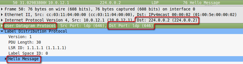
1. After LDP is enabled, LSR multicasts sending UDP datagrams to all interfaces to the address 224.0.0.2 and port 646, where LDP is activated - this is how the neighbors are searched.
The TTL of such packets is 1, since the LDP-neighborhood is established between directly connected nodes.
Such messages are called Hello .
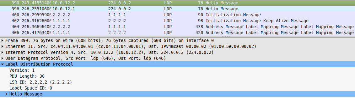
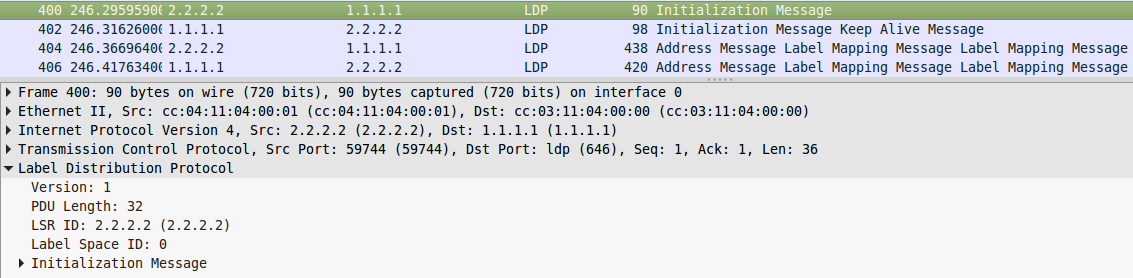
2. When neighbors are detected, a TCP connection is established with them, also on port 646 - Initialization . Further messages (except Hello) are transmitted already with a TTL of 255.
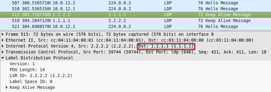
3. Now LSR periodically exchange messages Keepalive is addressable over TCP and still keep trying to find neighbors using Hello.
4. At some point, one of the LSRs finds a second person in itself — the Egress LSR — that is, it is the output for some FEC. This is a fact that you need to inform the world.
Depending on the mode, it waits for a request for a label for this FEC, or sends it immediately.
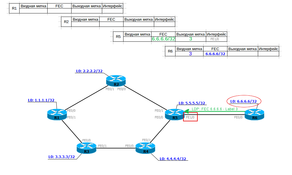
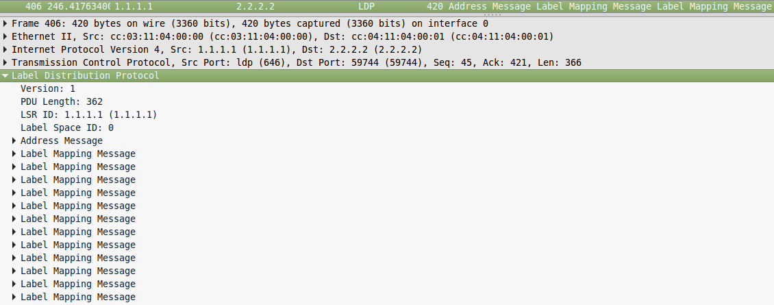
This information is transmitted in the message Label Mapping Message . Based on the name, it carries the correspondence of FEC and labels.
R5 receives information on the compliance of FEC 6.6.6.6/32 and label 3 (implicit null) and writes it into its table of labels. Now, when he needs to send data to 6.6.6.6, he will know that he needs to remove the top MPLS header and send the remaining packet to the FE1 / 0 interface.
Next, he selects the input label for this FEC, writes this information to his label table, and sends it to his upstream neighbors.
Now R5 knows that if an MPLS packet with a label of 20 arrived, it needs to be sent to the FE1 / 0 interface, removing the label, that is, following the PHP procedure.
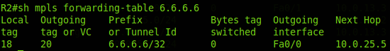
R2 receives from R5 information about compliance with the FEC-tag (6.6.6.6 - 20), inserts it into the table and, creating its input label (18), transmits it even higher. And so on, until all LSRs get their output label.

Thus, we have built LSP from R1 to R6. R1, when sending a packet to 6.6.6.6/32, adds a label 18 to it (Push Label) and sends it to port FE0 / 0. R2, receiving a packet with label 18, changes the label to 20 (Swap Label) and sends it to port FE0 / 0. R5 sees that for a packet with a label of 20, you need to run PHP (output label - 3 - implicit null), removes the label (Pop Label) and sends data to the port FE1 / 0.
At the same time, LSPs from R2 to R6, from R5 to R6, from R4 to R6, etc., were built in parallel. That is, from all LSR - I just did not show it in the illustration.
If you have enough strength, then on the gif below you can see the whole process in dynamics.
Naturally, you understand that not only R6 suddenly began sending out its own correspondences to the FEC-tag, but all the others - R1 about 1.1.1.1/32, R2 - 2.2.2.2/32 and so on. All of these messages are lightning fast spread across the MPLS network, building dozens of LSPs. As a result, each LSR will know about all existing FECs and a corresponding LSP will be built.
Again, on the gif above, the process is not fully shown, then R1 then transfers information to R3, R3 to R4, R4 to R5.
And if we look at R5, then we see that for FEC 6.6.6.6/32 we have more than one output label, as expected, but 3:
Moreover, R6 itself will record a label for FEC 6.6.6.6, which it will receive from R5:
Inuse - correct - imp-null towards R6. But the other two of the ring are from R2 and R4. This is not a mistake and not a loop - just R2 and R4 generated these labels for the FEC 6.6.6.6/32 routing table that he knows about.
There are two questions:
1) How does he plan to use them? They are stupid. The answer: no way. There can be no such situation in our network when 2.2.2.2 or 4.4.4.4 will be the next nodes on the way to 6.6.6.6 — IGP will not build a route like this. This means that tags will not be used. It's just that the LDP is stupid - its messages scatter across the entire network, making their way into every crack. A smart LSR already decides which one to use.
2) What about loops? Will the LDP message ply the network until the TTL expires?
And here everything is simple - receiving a new message Label Mapping Message does not initiate the creation of a new one - the resulting correspondence is simply recorded in the LDP table. That is, in our case, the R5 has already invented once the label for FEC 6.6.6.6/32 and sent it to its higher neighbors and it will not change until the LDP process restarts.
This is basic information on how LDP works.
In fact, everything here is very dependent on the manufacturer. In principle, LDP supports all kinds of work with tags: DoD / DU, Independent Control / Ordered Control, and Conservative / Liberal Label Retention. This is not regulated by the RFC, so each vendor is free to choose his own path.
For example, basically everyone uses DUs for LDP, but at the same time, Juniper tags are distributed in an orderly manner, and at Cisco independently.
Only Loopback LSR interfaces are selected as the FEC in Huawei and Juniper, and Cisco FEC is created for all entries in the routing table.
But all this is hardly somehow reflected on the real network.
The most important thing to understand about LDP is that it does not use dynamic routing protocols in its work — it works similarly to PIM DM in its operation: it floods the entire network with tags, but it relies on information from the LSR routing table. And if two labels for one FEC from different neighbors come to R1, then it will select for the LSP only the one that is received through the best interface before this FEC according to the information from TM.
This means three things:
And in general, after LDP is turned on, traffic will go the same way as without it, with the only difference that MPLS labels appear.
Including LDP, like IP, supports ECMP , just hash calculation algorithms, and accordingly balancing may differ.
An interesting article from Ivan Pepelnyak on the topic of LDP and a video on how the protocol works.
LDP is described in RFC 5036 .
Stay true to the network linkmeup.
OSPF is running, routers see Loopback and each other, MPLS is turned off.
Initial configuration file.
To enable MPLS globally, you need to give two commands:
The first is already standard de facto and de jure on almost any network equipment - it starts the CEF mechanism on the router, the second starts MPLS and LDP globally (can also be given by default).
The Router ID (and in the more general (non-cyclic) LSR ID terminology) in MPLS is straightforwardly chosen:
Naturally, do not trust the automatics - we will configure the LSR ID manually:
If you do not add the force keyword, the Router ID changes only when the LDP session is reset. Force forces the router to change its Router ID by force and, if necessary (if it has changed), reestablishes the LDP connection.
Next on the right interfaces, we give the command mpls ip :
Cisco here again uses its principle of a lazy engineer - a minimum of effort from the staff. The mpls ip command turns on the LDP interface simultaneously with MPLS, whether we like it or not. Similarly, the ip pim sparse-mode command enables IGMP on the interface, as I described it in the multicast article.
After activating the LDP, the router begins to probe the soil via UDP:
Checks are sent to multicast address 224.0.0.2.
Now we repeat all the same manipulations on R2
and enjoy the result.
R2 is also looking for neighbors.
We learned about each other, and R2 raises the LDP session:
Now they are neighbors, which is easily verified with the show mpls ldp neighbor command .

And then one tells the other about their correspondences FEC-tag:
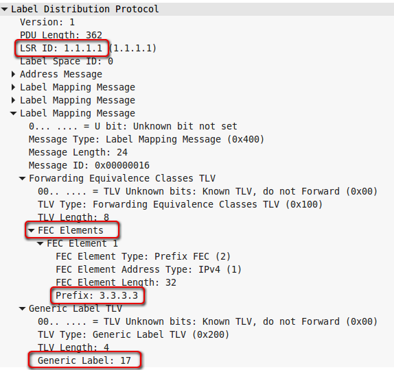
So R1 informs R2 that if he wants to send traffic for FEC 3.3.3.3 , he must use tag 17 .
Please note that LDP on R3 has not yet been raised, that is, R1 announced the label for FEC 3.3.3.3, without waiting for it from R5, this indicates that Independent Control is used.
And the fact that there was no explicit request from R2 for this FEC indicates that the mode is Downstrean unsolicited.
Next, the nodes will continue to monitor new neighbors using Hello LDP over UDP and exchange LDP Keepalive already targeted:
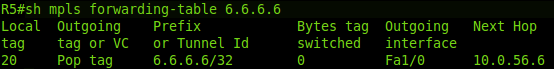
Now, using the show mpls forwarding-table command, you can see which tags have been assigned to each FEC:
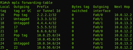
On the second line, the FEC 3.3.3.3 already considered, and we see that for it the local label is 17, that is, R1 will tell everyone that for FEC 3.3.3.3 it is 17, which was in the dump.
But outgoing tag or output tag - Untagged - this means that packets are sent to a pure IP (without any reservations on the stack). Moreover, Untagged means that there is no MPLS between R1 and R3 at all - that's right: we didn’t turn it on to R3.
But with R2 (first line) the situation is different. Local label 16 is what R1 will transmit to everyone. And the output - Pop tag . That is, when sending a packet to R2, R1 should remove the label. In our case, this means that pure IP will be transmitted (but in a more general case, only the top tag is removed). What is the difference with FEC 3.3.3.3? And the difference is that between R1 and R2 there is MPLS and what we see is the same PHP - Penultimate Hop Popping. A packet addressed to 2.2.2.2 will still be processed on R2, so in order not to produce entities beyond the necessary R1 will helpfully remove the label.
And then an interesting question arises, how does R1 know that it is the penultimate of the Mohicans? , LDP , , 2.2.2.2 R2 — , 2.2.2.2 10.0.12.2.
R2 R1:

3 — implicit-null. R2 , R1 MPLS .
— R1 3 R2 — . IP-. 3 MPLS.
3 MPLS, Pop Tag .
R5 R6 , MPLS , , R2, R2 FEC- . R6 MPLS R1 R2 .
, Ordered Control, R2 R5 R6, IP.
MPLS+LDP . — Neighbor Discovery, Initialization, , PHP.
:
LDP.
MPLS R1 :

FEC .
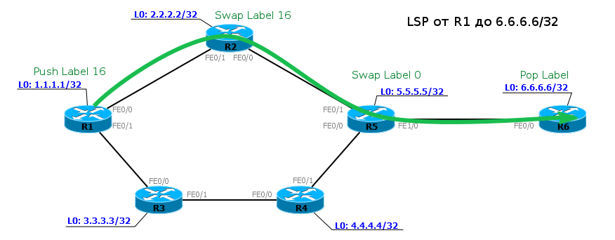
LSP R1 R6
R2:
R5:
1. R1 MPLS 21 , Fa0/0 18 .
2. R2 MPLS 18 , Fa0/0 20 .
3. R5 MPLS 20 , Fa1/0 — PHP .
LSR , - ip cef — .
, show mpls forwarding table — LFIB ( Lable Forwarding Information Base ) — — Data Plane. Control Plane? LDP ? ?
:
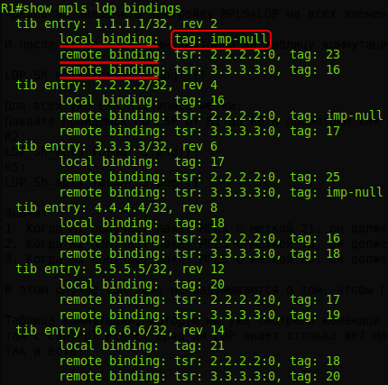
FEC :
local binding- what this LSR sends to the
remote binding neighbors - what this LSR has received from its neighbors.
In the illustration above, you can see the word "tib". TIB is the Tag Information Base , which is correctly called Label Information Base - LIB.
This is a relic of the late-born TDP - the progenitor of the LDP.
Notice that 2 remote binding everywhere are two ways to get tags. For example, you can get to R2 directly from R1, or you can get through R3-R4-R5-R2.
That is, you understand yes? Not only does he make FEC from each entry in the routing table, but this scoundrel also uses Liberal Retention Mode to hold tags.
Let's summarize: the default LDP in Cisco works in the following modes:
, .
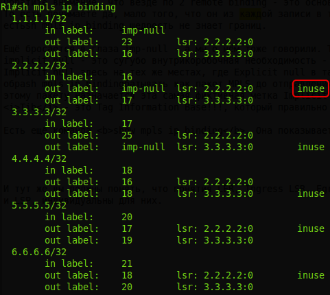
show mpls ip binding . , , LSP:
, , , LSP — Ingress LSR, , , LSP?
IP CEF. Ingress LSR , FEC .
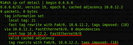
Next Hop
, LDP LER, Ingress LSR, Egress LSR — - . FEC LSP, . FEC Egress LSR Ingress LSR ( , ), LSP.
, LER LSP, , Ingress, Egress.
MPLS IGP-. , .
MPLS BGP. . , , BGP, MPLS VPN.
MPLS BGP .
BGP IGP , MPLS BGP. , BGP, , . MPLS BGP?
:
Now, in order to configure BGP on each router in our AS, we can only configure it on border routers to which clients or other providers are connected.
Let's look at the example of the network:
If we need to get from R1 to Filkin Certificate networks, we see that they are accessible through R6 and “fly through” through MPLS to address 6.6.6.6. And when we get to R6, he already knows where to go next. Similarly, it will be the opposite, in Balagan Telecom.
The configuration for this scheme and a couple of commands with information output can be found here .
LDP is good. It works simply and clearly. But there is such a technology as MPLS TE - Traffic Engineering. And the best route that the LDP can provide is not enough for her.
Traffic management implies that you can direct traffic between nodes as you like, given the various restrictions.
For example, in our network, the client has two points of connection of its nodes - on R1 and on R6. And between them, he asks for a VPN with a guaranteed channel width of 100 Mb / s. But at the same time, we also have regular broadband servers on the network chasing vkontaktik and a dozen other customers who rent a VPN, but they don’t need to reserve a band.
If you do not intervene in this situation, there may be an overload somewhere on R2, and you will not get 100 Mb / s for a dear client.
MPLS TE allows you to go through the entire network from the sender to the recipient and reserve resources on each node. If you are familiar with the concept of IntServ, then yes, it is she who organizes QoS all the way, instead of allowing each router to make a decision for the passing packet.
Actually, the RSVP ( Resource ReSerVation Protocol ) protocol was originally (in 1993) designed to organize IntServ in IP networks. He had to convey QoS information for a specific data flow to each node and force it to reserve resources.
In the first approximation, it works simply.
1) - 5 /. RSVP — Path Message . , IP- , .
2) Path . , .
3) , Path, . , , .
4) 5 / ( ), .
5) Path , Resv , .
6) , Resv, , , .
, .
— RSVP Traffic Engineering , — RSVP TE , MPLS TE.
, LDP — LSR LSP . , , — LSP .
RSVP TE LSP, , , , , , .
MPLS TE . , RSVP TE LSP.
— LSP, LSR.
, RSVP . .
0) R1 LSP FEC 6.6.6.6/32. Tunnel R1, 6.6.6.6 Traffic Engineering.
1) RSVP Path 6.6.6.6. — Label Request . Path FEC — .
2) Path 6.6.6.6. Etc.
3) Path Egress LSR. , - , Resv. — Label . Egress LSR FEC , .
4) Resv , . LSP, , .
( Path ), ( Resv ).
, Downstream on Demand + Ordered Control. Path , Resv , LSR, .
Stop! , RSVP TE LDP , IGP, « 6.6.6.6».
RSVP TE LDP. RSVP TE , — , .
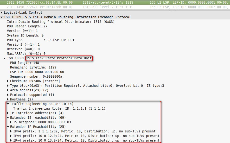
- , , (link-state), OSPF ISIS.
- , OSPF ISIS . OSPF LSA — Opaque LSA , ISIS — TLV IS Neighbor IP Reachability .
- , Ingress LSR Egress LSR SPF — CSPF ( Constrained Shortest Path First ).
Now more.
Path . — R1, — 6.6.6.6. .

Path FIB , , . , .
Ingress LSR .
, RSVP TE . , ? RSVP , , OSPF ISIS. , RIP, IGRP EIGRP — , — Feasible Successor.
SPF , AD , .
CSPF. , , , - , - , .
RSVP TE CSPF - .
, IGP? . Constraints — . RSVP TE — , , , LSP . , CSPF , . , — , .
OSPF ISIS , , . .
, OSPF 3 LSA:
Opaque ( OSPF). LSA, OSPF . . TE ( TED — Traffic Egineering Database ). TE — , - , Opaque LSA.
ISIS. : IS-IS TLV 22 (Extended IS Reachability), 134 (Traffic Engineering router ID), 135 (Extended IP reachability).
, .
0) R1 MPLS TE ISIS (OSPF) TE. . TED. RSVP .

1) , (Traffic Engineering), (6.6.6.6) . LSR CSPF: R1 6.6.6.6 . — (R2, R5, R6).
2) RSVP ERO . R1 RSPV Path, , , ERO. — 6.6.6.6. , Label Request, , FEC (6.6.6.6/32).
3) RSVP Path — , ERO. IGP ERO , R2.
4) R2, RSVP Path, , , MPLS FEC 6.6.6.6/32. Path , ERO — R2. , R2. ERO : (R5, R6). R2 Path R5.
5) R5 : , , ERO, Path , ERO — R6.
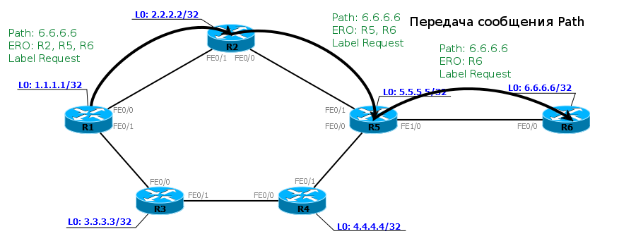
6) R6, , , . Path, FEC 6.6.6.6 Label Resv.
, , , LSR, .
7) RESV R1 (Ingress LSR), LSP. Resv , Path, .
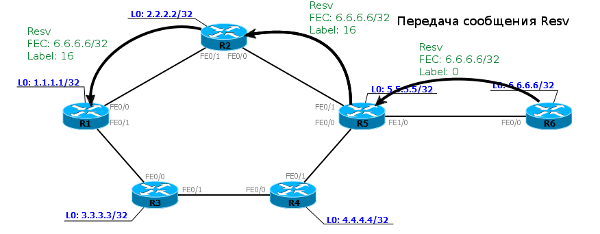
8) LSP R1 6.6.6.6 . R1 R6. , R6 1.1.1.1 — .
— Path 6.6.6.6, ? — . ERO Ingress LSR Egress LSR — . LSR , . Ingress LSR .
IGP. , OSPF ISIS , . ( ) SPF. .
, IGP (link-state), — - — , , — , , , ABR .
, , MPLS TE — CSPF , — , .
Explicit Path ( ERO). , , LSP — , LSP. Ingress LSR . CSPF .
Explicit Path ? .
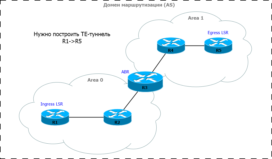
, :
Explicit-path: R1, R3, R5.
Explicit Path CSPF, , , Area 0: R1 R3.
, , ERO, Explicit-path — R5. : R1, R2, R3. Path ERO, R3. , - , , - Explicit-path CSPF. (R3, R4, R5), ERO, .
Ingress LSR Egress LSR , ABR.
, Explicit Path , , , LSP , LSP.
, MPLS TE.
mpls ip LDP. — .
mpls traffic-eng tunnels . TE- RSVP TE:
:
. RSVP .
IGP TE. ISIS:
— , TE .
LSR-ID, LDP,
ISIS, , TE .
.
ISIS TE:
LSR-ID, ( TE), .
TED.
ISIS: #show isis database verbose
RSVP .
TE-.
— . L2TP, GRE, IPIP , , MPLS TE.
ip unnumbered Loopback0 , Loopback0.
tunnel destination 6.6.6.6 — , , .
tunnel mode mpls traffic-eng — . , .
tunnel mpls traffic-eng path-option 10 dynamic — CSPF , .
, :
?
R1 Path.
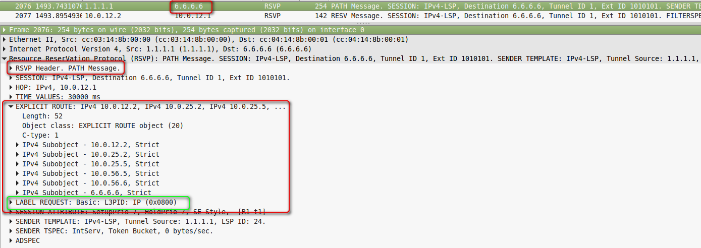
R1-R2.
, ERO Label Request.
— 6.6.6.6, .
Explicit Route:
10.0.12.2 -> 10.0.25.2 -> 10.0.25.5 -> 10.0.56.5 -> 10.0.56.6.
. LSR , Path.
ERO 10.0.12.1, R1 .
Label Request , LSR FEC.
Path — .
Resv , Resv LSR.
R5:

R2-R5.
R2-R5.
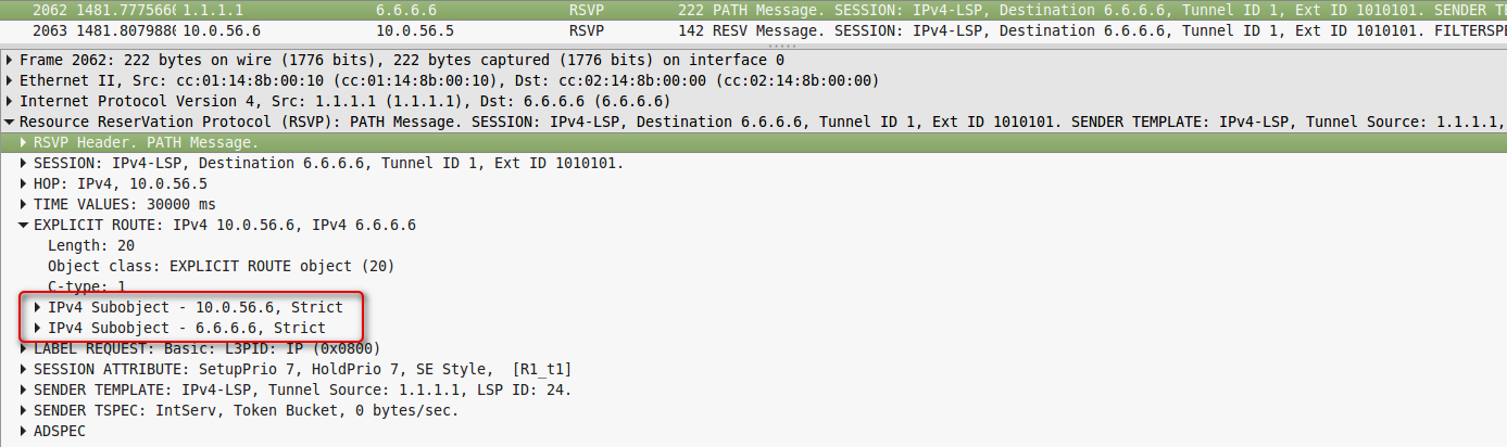
Path R6. RSPV Resv:

R5-R6.
, Resv .
Label , FEC.
, R6 0 — Expliit Null. — , MPLS R5 R6 ( EXP, ), R6 , 0 , , .
, (, VPN), RFC 3032 ( ) R5 , , 0. , , .
, , 0 , — . RFC 4182 . 0 .
— PHP. , — 3 — LSR PHP 0. .
R5 Resv R2, R2 R1.
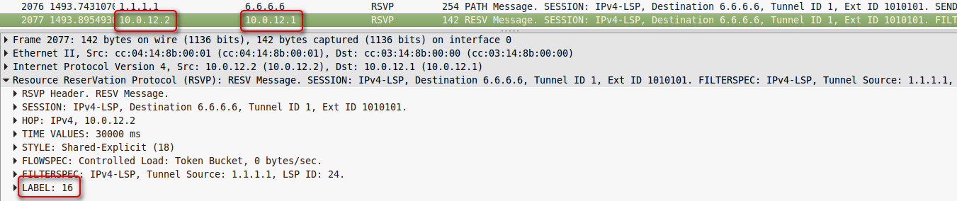
R1-R2.
, , — 16.
— R1-R3-R4-R5-R6.
: - explicit-path:
:
, , — 5 10. explicit-path, - , R1 LSP ( -).
:
Path, ERO:

, show mpls traffic-eng tunnels :
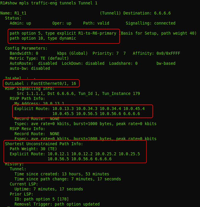
:

LSP , Loose Strict, FRR make before break, Affinity , MPLS TE.
RSVP-TE .
1: RSVP TE LSP LDP LSP?
2: Explicit Path ERO?
3: LDP (RSVP TE) /, LSP , , IP, MPLS?
4: , MPLS — - , , MPLS TE-? IGP.
5: - Explicit Null Implicit Null? ?
6: FEC LSR ?
, MPLS , . LSP , .
LPD over TE. RSVP-TE Traffic Engineering, LDP VPN, .
Egress LSR, MPLS , . . . MPLS VPN.
JDima .
.
— .
the gluck
But they are not enough. BBA services are good and necessary, but there is still a huge potential market for corporate customers who need a VPN.
The guys thought about it, puzzled and came to the conclusion that there is no way to do without MPLS.
If the multicast was the first topic that required some rebuilding of the understanding of IP networks, then while studying MPLS, you definitely have to forget almost everything that you knew before - this is a special world with its own rules.
')
Today in issue:
- What is MPLS
- MPLS network traffic transmission
- Terminology
- Label distribution
- - Methods of distribution of tags
- - - - DU vs DoD
- - - - Ordered Control vs. Independent Control
- - - - Liberal Label Retention Mode vs Conservative Label Retention Mode
- - - - PHP
- - Label Distribution Protocols
- - - - LDP
- - - - - Practice
- - - - Use pure MPLS in conjunction with BGP
- - - - RSVP-TE
- - - - - Practice
- - Q & A
- - Useful links
And we start with the question: "What is wrong with IP?"
Traditional video
And really, what's wrong? Why fence MPLS?
Yes, everything is so. The advantages and disadvantages of IP derive from the fact that it appeared later than classic networks and is incredibly flexible. Nowadays, there is a transition to packet switching, which is based on IP at the network level, and Ethernet is gaining more and more popularity on the channel link.
This is good, because now, on the basis of one backbone network and access network, you can provide broadband access , IP-telephony, IPTV and other possible services.
The same can be seen in the networks of mobile operators. The network of the second generation at the dawn were entirely on the basis of circuit switching . The core of 3G networks is for the most part IP, but telephony services can still be provided in circuit-switched mode. 4G networks are already full-fledged IP networks, where voice transmission is only one of the applications, as well as broadband access.
However, there is still a huge number of segments that use old technology. For example, somewhere there is ATM, in another place you need to transfer PDH from one part of the network to another, and then the client wanted his piece of Ethernet-network to be accessible from the other end of the city as if he was connected directly - in other words VPN.
As it was solved before: you need an ATM between two geographic points - build a channel between them based on ATM, PDH - build PDH.
And you want to do all this through one network, and not to build a separate one for each type of traffic.
For this, GRE, PPPoE, PPPoA, ATM over Ethernet, TDM over IP, and numerous other over'y were invented at one time. You can create another thousand others to cover all the combinations, and universal happiness will come in the chaos of standards ( by the way, some small manufacturers have gone this way ).
In the mid-90s, hotheads from several companies (IBM, Toshiba, Cisco, Ipsilon) came up with the idea of creating a mechanism for routing not looking inside the package and combining the routing table in search of a better way, but to be guided by a certain label. Shot from Cisco, and the mechanism was called plain: TAG Switching.
Moreover, the goal pursued by the developers was to allow high-speed switches to transmit traffic exclusively in hardware. The fact is that hardware IP routing has been an inaccessible pleasure for a long time, and it was impractical to use it on low-cost switches, and making decisions based on the label could be simple and fast.
But at the same time, super-large-scale integrated circuits have appeared (even if I do not agree with this term - the English VLSI describes the essence much better), and the task of saving on analyzing the contents of the package was not so relevant. In addition, the concept of FIB appeared, which assumes that for each packet it is not necessary to search for a destination in the routing table and accordingly involve the central processor - all hot information is already on the line card.
That is, in essence, the need for such a mechanism has disappeared.
But suddenly it became clear that label switching has unplanned potential - it doesn’t matter what is under the label - IP, Ethernet, ATM, Frame Relay. It also gives you the opportunity to get rid of the limitations of IP routing.
Hence the technology approved by IETF - MPLS - MultiProtocol Label Switching. It was the year 1997.
And this, seemingly insignificant, detail gave rise to a new era in telecommunications. Today MPLS can be found in any more or less large provider.
Main MPLS applications now:
- MPLS L2VPN
- MPLS L3VPN
- MPLS TE
We will talk about each of them in separate articles - these are monstrously huge topics. But we will briefly touch them at the end of the article.
MPLS
By itself, pure MPLS is rarely used. The performance gain is insignificant, because the difference between looking at the FIB / changing some fields in the headers and seeing the table of labels / changing the label in the MPLS header is not that big. Of course, its applications listed above are used.
But in this article we will concentrate on pure MPLS, in order to understand how it works in its most basic form.
Below we will also consider one application of pure MPLS.
Despite the fact that MPLS is not tied to the type of network on which it will work, in our time it lives in symbiosis only with IP. That is, the network itself is built on top of IP, but at the same time it can transfer data from many other protocols.
But let's get to the point, and first I want to say that MPLS does not replace IP routing , but works on top of it.
To be more specific, I will take such a network.
Now it is fully operational, but without any hint of MPLS. That is, R1, for example, sees R6 and can ping it with Loopback.
PC1 sends an ICMP request to server 172.16.0.2. An ICMP request is an IP packet. On R1, according to the basic principles, the packet goes through the FE0 / 0 interface on R2 - the Routing Table said so.
R2, after receiving the packet, checks the destination address, looks at its FIB, sees the next router and sends the packet to the FE0 / 0 interface.
And this process is repeated time after time. Each router independently decides the fate of the packet.
This is how a traffic dump looks quite familiar:
What happens if we activate MPLS? Immediately, at the same second the world changes. After that, the label tables are filled in on routers and numerous LSPs are built.
And now the same path will be done a little differently.
When an IP packet from PC1 enters the MPLS network, the first router hangs a label, then this packet goes to the destination point, and each next router changes one label to another. When you exit the MPLS network, the label is removed and the already clear IP packet is transmitted as it was at the very beginning.
This is the basic principle of MPLS - routers switch packets by tags without looking inside the MPLS packet. The first one adds, the last one deletes.
Let us consider, step by step, the transfer of a data packet from PC1 to the destination node:
1. PC1 - a normal computer - sends a normal package to a remote server.
2. The package reaches R1. It adds label 18. It is inserted between the IP header and Ethernet.
This information can be obtained from the FIB:
The FIB shows that the packet with the addressee 6.6.6.6 needs to be labeled 18 and sent to the interface FE0 / 0 .
Actually, this is what he does: he adds the heading and writes 18 to it:
Dump between R1 and R2 .
3. R2 receives this packet, sees in the Ethernet header that it is an MPLS packet (Ethertype 8847), reads the label and refers to its tag table:
We read the letters: if the MPLS packet came with a mark of 18, you need to change it to 20 and send the packet to the FE0 / 0 interface.
Dump after R2.
4. R5 performs similar actions - sees that a packet with a label of 20 has arrived, it needs to be changed to 0 and sent to FE1 / 0. Without any access to the routing table.
5. R6, having received the MPLS package, sees in its table that the label must now be removed. And, having removed it, he already sees that the recipient of the packet - 172.16.0.2 - is a Directly Connected network. Next, the packet is transmitted in the usual way by the routing table already without any tags.
That is, the whole process looks like this:
We will not consider the end nodes in order not to complicate the scheme.
So far, it seems, everything is simple, even if it is not clear why.
Now the IGP and MPLS domains are the same, and MPLS only promises to us in the future some kind of buns: L2VPN, L3VPN, MPLS TE.
But, in fact, even basic MPLS gives us advantages if we remember that we are a provider.
As a provider, we do not use IGP protocols for routing between ASs. For this we use BGP. And it is in conjunction with BGP that the benefits of MPLS will become clear.
Consider our network in conjunction with neighboring AS:
From the BGP release, we know that BGP must be configured on every router in our AS. Otherwise we will not be able to transfer traffic from neighboring AS and our customers through our AS. Each router must know all routes.
But that was before MPLS!
When MPLS is configured on our network, we no longer have to configure BGP on every router on the network. It is enough to configure it only on border routers in the AS, on those that are connected to other clients or providers.
But this is not all good news. In addition to the fact that BGP can now not be configured on each router in the AS, routers also do not need to create a label for each BGP prefix. It is enough to know how to get to the IP address, which is listed as next-hop. That is, if the BGP session is configured between Loopback0 R1 and Loopback0 R6, then nothing changes in the table of labels, even if each of them sends hundreds of thousands of routes via BGP:
For example, several routes have come to router R1 via BGP from router R6:
Let's see how the packets that go to the network 100.0.0.0/16 will be processed:
In the output above, it is clear that packets 27 will be added to the packets.
And, if you look at the table of labels, then there are no labels for routes that are known from BGP, but there is a label 27 and it corresponds to 6.6.6.6/32. And this is exactly the address that we saw in the routes that came on BGP from R6:
An example of the setting you can find below .
We ran a little ahead, but now that it has become clearer what advantages even basic MPLS gives, we can plunge into the conceptual apparatus in the world of MPLS.
Terminology
Label - a label - a value from 0 to 1,048,575. Based on it, the LSR decides what to do with the package: which new label to hang, where to transfer it.
It is part of the MPLS header.
Label Stack - a stack of labels. Each package can carry one, two, three, but at least 10 tags - one above the other. The decision about what to do with the package is made on the basis of the upper tag. Each layer plays its own role.
For example, when transmitting a packet, a transport label is used, that is, a label that organizes transit from the first to the last MPLS router.
Others may carry information that this packet belongs to a particular VPN.
In this release there will always be only one label - more is not needed yet.
Push Label — the operation of adding a label to a data packet — is done at the very beginning — on the first router in the MPLS network (in our example, R1).
Swap Label - label replacement operation - occurs on intermediate routers in the MPLS network - the node receives a packet with one label, changes it and sends it with another (R2, R5).
Pop Label - label removal operation - performed by the last router - the node receives the MPLS packet and removes the top label before passing it on (R6).
In fact, a label can be added and removed anywhere within the MPLS network.
It all depends on the specific services. It would be more correct to say that the label is added by the first path router (LSP), and is removed last.
But for simplicity, in this article we will talk about the boundaries of the MPLS network.
In addition, the removal of the top label does not mean that there is a pure IP packet left, if we are talking about a stack of tags. That is, if a Pop Label operation was performed on a package with three labels, then there are two labels left and then it is still processed as MPLS. And in our example there was one, and after that there would be no one left - and this is already an IP case.
LSR - Label Switch Router is any router in the MPLS network. It is called that because it performs some operations with labels. In our example, these are all nodes: R1, R2, R3, R4, R5, R6.
LSR is divided into 3 types:
Intermediate LSR - MPLS intermediate router - it performs the Swap Label operation (R2, R5).
Ingress LSR - “input”, the first MPLS router - it performs the Push Label (R1) operation.
Egress LSR is “output”, the last MPLS router is performing the Pop Label (R6) operation.
LER - Label Edge Router is a router at the edge of the MPLS network.
In particular, Ingress LSR and Egress LSR are boundary, which means they are also LER.
LSP - Label Switched Path - label switching path. This is a unidirectional channel from the Ingress LSR to the Egress LSR, that is, the path that the packet will actually go through the MPLS network. In other words, it is the LSR sequence.
It is important to understand that the LSP is in fact unidirectional. This means that, firstly, traffic is transmitted only in one direction, secondly, if there is “there”, it does not necessarily exist “back”, thirdly, “back” does not necessarily follow the same path, that "there". Well, it's like the tunnel interfaces in GRE.
What does LSP look like?
Yes, that's so unpredictable.
This is a compiled output from four LSRs - R1, R2, R5, R6. That is, on the LSR you will not see the complete sequence of nodes from the input to the output, according to the type of the AS-PATH attribute in BGP. Here, each node knows only the input and output labels. But the LSP does exist.
This looks a bit like IP routing. Despite the fact that there is a path from point A to point B, the routing table only knows the next node to send traffic to. But the difference is that the LSR does not decide on each packet based on the destination address — the path is determined in advance.
And one of the most important concepts that you need to understand - FEC - Forwarding Equivalence Class . For some reason it was very hard for me, although in fact everything is simple. FEC are traffic classes. In the simplest case, the class identifier is the destination address prefix (roughly speaking, the IP address or the destination subnet).
For example, there are traffic flows from different clients and different applications that go all to the same address — all these flows belong to the same class — one FEC — use the same LSP.
If we take other streams from other clients and applications to another destination address, this will be a different class and another LSP respectively.
In theory, in addition to the destination address, FEC can take into account, for example, QoS labels, source address, VPN identifier, or application type. It is important to understand here that packets of one FEC are not required to follow to the same destination address. And at the same time, even if two packages follow to one place, they will not necessarily belong to one FEC.
I will explain why all this is necessary. The fact is that for each FEC, its own LSP is selected — its own path through the MPLS network. And then, for example, for WEB-surfing, you set the QoS BE priority - this will be one FEC - and for VoIP - EF - the other FEC. And then you can specify that for the FEC BE the LSP should go in a wide but long and unguaranteed way, and for the FEC EF it can be narrow but fast.
Unfortunately or fortunately, but now only an IP prefix can act as an FEC. Things like QoS marking are not considered.
If you pay attention to the label table, the FEC is there, since the label replacement parameters are determined just on the basis of the FEC, but this is done only at the first moment in time - when these labels are distributed. When real traffic is running on the LSP, no one except Ingress LSR looks at it — only labels and interfaces. Ingress LSR takes all the work to determine the FEC and in which LSP to send traffic - after receiving a clean packet, it analyzes it, checks which class it belongs to, and hangs the corresponding label. Packages of different FECs will receive different labels and will be sent to the appropriate interfaces.
Packages of the same FEC receive the same label.
That is, intermediate LSRs are threshers, which for all transit traffic only do the switching of tags. And all the intellectual work is done by Ingress LSR.
LIB - Label Information Base - a table of labels. Analogue of the routing table (RIB) in IP. It indicates for each input label, what to do with the package - change the label or remove it and which interface to send.
LFIB - Label Forwarding Information Base - by analogy with the FIB - this is the label base that the network processor refers to. When you receive a new package, there is no need to contact the CPU and lookup into the table of tags - everything is already at hand.
One of the initial ideas of MPLS - to maximize the spread of Control Plane and Data Plane - went into oblivion.
Developers wanted that when transmitting a packet through a router there was no analysis - just read the label, changed it to another one, transferred it to the correct interface.
To achieve this, there were just two separated processes - a relatively long construction of a path (Control Plane) and a fast transfer of traffic along this path (Data Plane)
But with the advent of cheap chips (ASIC, FPGA) and the FIB mechanism, the usual IP transmission also became fast and simple.
For the router, it doesn't matter where to look when sending a packet - in the FIB or in the LFIB.
But what is undoubtedly important and useful is that MPLS’s indifference to what is transmitted under its heading — IP, Ethernet, ATM. No need to fence GRE or any other uncomfortable VPNs before the pain in the joints. But let's talk more about this.
MPLS header
The entire MPLS header is 32 bits. The format of the fields and their length are fixed. Often the entire title is called a tag, although this is not entirely true.
Label is the label itself. The length is 20 bits.
TC - Traffic Class. It carries the packet priority, as the DSCP field in IP.
Length 3 bits. That is, it can encode 8 different values.
For example, when an IP packet is transmitted over an MPLS network, the value in the DSCP field is definitely assigned the value of TC. Thus, a packet can be processed almost equally in queues all along its path, both on a pure IP site and in MPLS.
But, naturally, this is a lossy conversion — the six bits of the DSCP are closely in 3 bits of TC: 64 against 8. Therefore, there is a special correspondence table, where the whole range is just one value.
Initially, the field was called EXP (experimental), and its contents were not regulated. It was assumed that it can be used for research, the introduction of new functionality. But this is in the past.
If someone argues with you that this field is experimental and not formally approved for the QoS function, itdoes not look fartherbehind life .
=====================Problem number 1
The network has a simple QoS policy configured in which IP packets that come from host 10.0.17.7 to address 6.6.6.6 are marked and transmitted over the MPLS network. For marking of packages, the EXP field is used, the value of field 3.Scheme
R6 QoS, EXP.
, , R6 . , , EXP 3 class default.
: , R6 .
R7 . MPLS R7 R1 .
.
=====================
S — Bottom of Stack — 1 . MPLS , , MPLS, VPN. LSR . S «1», ( ) «0», ( ). LSR , , , — - . , , . , , , : MPLS - (IP, Ethernet, ATM, FR ).
: “, , , ” — . MPLS, , ( Ethertype Ethernet' Protocol IP).
— — , , , ?
— , , , , — IP Ethernet -. . , Pop Label, ( ) , .
, — , (LIFO — Last Input — First Output).
, , MPLS , — .
TTL — Time To Live — IP TTL . — 8 . — . IP- MPLS IP TTL MPLS TTL, . 255, IP IP TTL , .
, MPLS , — IP — . MPLS 2,5 , — Shim-header — -.
, MPLS. IETF, ATM, AAL5, Frame Relay.
:
As mentioned above, there may be 2 ^ 20 labels.
Some of them are reserved:
0 : IPv4 Explicit NULL Label . "Explicit empty label." It is used on the very last MPLS span - before the Egress LSR - in order to notify it that this 0 mark can be removed without looking at the tag table (more precisely LFIB).
For those FECs that originate locally (directly connected), Egress LSR selects label 0 and sends it to its neighbors — the penultimate LSR (Penultimate LSR).
When transmitting a data packet, the penultimate LSR changes the current label to 0.
When the Egress LSR receives a packet, it knows for sure that the top label just needs to be removed.
This was not always the case. , 0 , LSR MPLS .
- , , .
0 () Pop Label , .
1 : Router Alert Label — Router Alert IP — , . , , , — , 1.
2 : IPv6 Explicit NULL Label — , 0, IP.
3 : Implicit Null . , MPLS Egress LSR. , MPLS . .
4-15 : .
Depending on the vendor, other tag values can be fixed, for example, on Huawei equipment, labels 16-1023 are used for static LSPs, and everything above is in dynamic ones. In Cisco, available tags start at the 16th.
=====================
In the following diagram, all routers except R5 are Huawei routers. R5 - Cisco.Scheme
For the R5 router configuration below, you need to configure it so that the distribution of tag values matches Huawei. Speech that in Huawei dynamic tags begin with 1024, and in Cisco with 16.R5 configurationip cef ! interface Loopback0 ip address 5.5.5.5 255.255.255.255 ip router isis ! interface FastEthernet0/0 description to R4 ip address 10.0.45.5 255.255.255.0 ip router isis mpls ip ! interface FastEthernet0/1 description to R2 ip address 10.0.25.5 255.255.255.0 ip router isis mpls ip ! interface FastEthernet1/0 description to R6 ip address 10.0.56.5 255.255.255.0 ip router isis mpls ip ! router isis net 10.0000.0000.0005.00 ! mpls ldp router-id Loopback0 force
Details of the problem here .
=====================
In general, it became clear how traffic is transmitted and how MPLS tags are involved.
But tags are not taken from the bald - no one needs additional chaos on the eve of the New Year. Special protocols allocate labels between the Egress LSR and Ingress LSR, creating the LSP.
Label distribution
First, as you already understood, on some devices you can do everything manually - vivat diligence and diligence!
But in the era of automatic washing machines, there are three basic protocols for distributing tags - LDP, RSVP-TE and MBGP.
In short, the LDP - the easiest and most understandable way - is based on the routing information of the nodes. RSVP-TE is a development of the once-developed but unpopular RSVP protocol — it is used in MPLS-TE to build LSPs that meet certain conditions. IGP supporting Traffic Engineering (OSPF, ISIS) are necessary for its work.
MBGP is a close relative of BGP, but it’s a protocol from a slightly different story, it passes tags for other purposes. Therefore, it stands aside from the LDP and RSVP-TE.
Let's talk about each of them, but before that, a few words about how LSRs handle tags in general.
Tag Distribution Methods
The first obvious fact is that the tags are distributed in the direction from the traffic receiver to the sender, and more precisely from the Egress LER to the Ingress LER. The first unobvious fact - in MPLS Downstream - is from the sender to the receiver, and Upstream from the receiver to the sender. For myself, I defined it this way: LSP “grows” from FEC up to Ingress LER, like a tree, and user traffic “goes down” to the recipient along the LSP, like rainwater along branches. That is, tags are distributed to meet traffic.
They also say that the LSP is built to meet traffic.
The very mechanism of distribution of tags depends on the protocol, settings and manufacturer.
DU vs DoD
First , the router can distribute tags to all its neighbors immediately and without unnecessary questions, and can issue it on request from the superiors (we remember, yes, which direction is called Upstream?)
The first mode is called DU - Downstream Unsolicited . As soon as the LSR learns about FEC, it sends tags to all its MPLS neighbors for this FEC.
It looks like this:
All LSRs will learn about all FECs in all possible ways. First, the FEC-tagging diverges across the entire network from neighbor to neighbor, almost as it does with the BootStrap messages in the PIM SM. And then each LSR chooses only the one that came along the best path, and uses it for the LSP - Reverse Path Forwarding in the same PIM SM works in the same way.
Quickly, simply, clearly, although it is not always necessary for everyone to know everything.
The second mode - DoD - Downstream-on-Demand . The LSR knows the FEC, it has neighbors, but until they ask what label is for this FEC, the LSR remains silent.
This method is convenient when some requirements are imposed on the LSP, for example, on the bandwidth. Why send a tag just like that if it is immediately dropped? Better, the superior LSR will ask the downstream: I need a label from you for this FEC - and that one is: “ok, on”.
The tag selection mode is interface specific and is determined at the time the connection is established. Both ways can be used on the network, but on the same line, neighbors should only agree on one specific one.
Ordered Control vs. Independent Control
Second , the LSR can wait for the FEC label to come from the Egress LER side before telling its upstream neighbors. Or maybe send out tags for FEC as soon as I found out about him.
The first mode is called Ordered Control.
Ensures that by the time of data transfer all the way up to the output LER will be built.
The second mode is Independent Control .
That is, tags are transmitted in an irregular manner. Convenient in that traffic can begin to transmit even before the entire path is built. The same is dangerous.
Liberal Label Retention Mode vs Conservative Label Retention Mode
Thirdly , it is important how the LSR handles the labels passed to it.
For example, in such a situation, should R1 store the information about tag 20 received from neighbor R3, which is not the best way to get to R6?
And this is determined by the label holding mode.
Liberal Label Retention Mode - tags are retained. In the case when R3 becomes the next step (for example, problems with the main route), the traffic will be redirected more quickly, because the label is already there. That is, the reaction rate is higher, but the number of tags used is also large.
Conservative Label Retention Mode - an extra label is discarded as soon as it is received. This reduces the number of tags used, but MPLS will respond more slowly in the event of an accident.
Php
No, this is not the PHP you thought of. It's about Penultimate Hop Popping . All the engineers are a little optimizers, and here the guys thought: why should we process the MPLS headers twice - first on the penultimate router, then on the output one.
And they decided that the label should be removed on the penultimate LSR and called this action - PHP.
For PHP there is a special label - 3.
Returning to our example, for FEC 6.6.6.6 and 172.16.0.2 R6 allocates label 3 and reports it to R5.
When sending a packet to R6, R5 should assign it a dummy tag - 3, but in fact it does not apply and a bare IP packet is sent to the interface (note that PHP only works on IP networks) - that is, the Pop Label procedure was performed on R5 .
Let's follow the life of the package, taking into account everything that we now know.
With how traffic is transmitted, it seems, more or less clear. But who performs all the titanic work on creating labels, filling in tables?
Label Distribution Protocols
There are not so many of them - three: LDP, RSVP-TE, MBGP.
There are two global goals - the distribution of transport marks and the distribution of service tags.
Explain that transport labels are used to transmit traffic over an MPLS network. These are the ones we are talking about the whole issue. LDP and RSVP-TE are used for them.
Service tags are used to separate different services. This is where MBGP and the LDP process - tLDP come into the arena.
In particular, MBGP allows, for example, to mark that such a route belongs to such a VPN. Then he sends this route as a vpn-ipv4 family to his neighbor with a tag, so that he can then separate the flies from the chops.
So, so that he could separate, and he needs to report on compliance label-FEC.
But this is the action of another play, which we will play in another six months or a year.
A prerequisite for the operation of all dynamic label distribution protocols is the basic setting of IP connectivity. That is, the network must be running IGP.
Well, now, when I have completely confused you, you can begin to unravel.
So what is the easiest way to distribute tags? The answer is to enable LDP.
LDP
The protocol with a very transparent name - Labed Distribution Protocol - has an appropriate working principle.
Consider it on the network linkmeup, which we muzyzhim entire issue:
1. After LDP is enabled, LSR multicasts sending UDP datagrams to all interfaces to the address 224.0.0.2 and port 646, where LDP is activated - this is how the neighbors are searched.
The TTL of such packets is 1, since the LDP-neighborhood is established between directly connected nodes.
Generally speaking, this is not always the case - a LDP session can be established for certain purposes and with a remote node, then it is called tLDP - Targeted LDP . We will talk about it in other issues.
Such messages are called Hello .
2. When neighbors are detected, a TCP connection is established with them, also on port 646 - Initialization . Further messages (except Hello) are transmitted already with a TTL of 255.
3. Now LSR periodically exchange messages Keepalive is addressable over TCP and still keep trying to find neighbors using Hello.
4. At some point, one of the LSRs finds a second person in itself — the Egress LSR — that is, it is the output for some FEC. This is a fact that you need to inform the world.
Depending on the mode, it waits for a request for a label for this FEC, or sends it immediately.
This information is transmitted in the message Label Mapping Message . Based on the name, it carries the correspondence of FEC and labels.
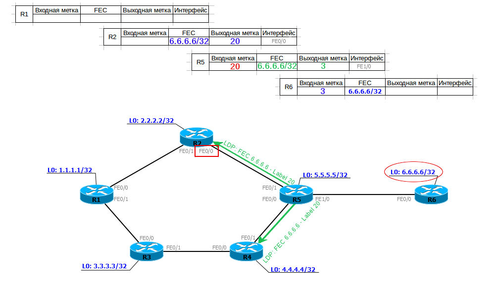
R5 receives information on the compliance of FEC 6.6.6.6/32 and label 3 (implicit null) and writes it into its table of labels. Now, when he needs to send data to 6.6.6.6, he will know that he needs to remove the top MPLS header and send the remaining packet to the FE1 / 0 interface.
Next, he selects the input label for this FEC, writes this information to his label table, and sends it to his upstream neighbors.
Now R5 knows that if an MPLS packet with a label of 20 arrived, it needs to be sent to the FE1 / 0 interface, removing the label, that is, following the PHP procedure.
R2 receives from R5 information about compliance with the FEC-tag (6.6.6.6 - 20), inserts it into the table and, creating its input label (18), transmits it even higher. And so on, until all LSRs get their output label.
Thus, we have built LSP from R1 to R6. R1, when sending a packet to 6.6.6.6/32, adds a label 18 to it (Push Label) and sends it to port FE0 / 0. R2, receiving a packet with label 18, changes the label to 20 (Swap Label) and sends it to port FE0 / 0. R5 sees that for a packet with a label of 20, you need to run PHP (output label - 3 - implicit null), removes the label (Pop Label) and sends data to the port FE1 / 0.
At the same time, LSPs from R2 to R6, from R5 to R6, from R4 to R6, etc., were built in parallel. That is, from all LSR - I just did not show it in the illustration.
If you have enough strength, then on the gif below you can see the whole process in dynamics.
Naturally, you understand that not only R6 suddenly began sending out its own correspondences to the FEC-tag, but all the others - R1 about 1.1.1.1/32, R2 - 2.2.2.2/32 and so on. All of these messages are lightning fast spread across the MPLS network, building dozens of LSPs. As a result, each LSR will know about all existing FECs and a corresponding LSP will be built.
Again, on the gif above, the process is not fully shown, then R1 then transfers information to R3, R3 to R4, R4 to R5.
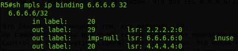
And if we look at R5, then we see that for FEC 6.6.6.6/32 we have more than one output label, as expected, but 3:
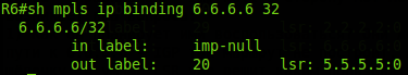
Moreover, R6 itself will record a label for FEC 6.6.6.6, which it will receive from R5:
Inuse - correct - imp-null towards R6. But the other two of the ring are from R2 and R4. This is not a mistake and not a loop - just R2 and R4 generated these labels for the FEC 6.6.6.6/32 routing table that he knows about.
There are two questions:
1) How does he plan to use them? They are stupid. The answer: no way. There can be no such situation in our network when 2.2.2.2 or 4.4.4.4 will be the next nodes on the way to 6.6.6.6 — IGP will not build a route like this. This means that tags will not be used. It's just that the LDP is stupid - its messages scatter across the entire network, making their way into every crack. A smart LSR already decides which one to use.
2) What about loops? Will the LDP message ply the network until the TTL expires?
And here everything is simple - receiving a new message Label Mapping Message does not initiate the creation of a new one - the resulting correspondence is simply recorded in the LDP table. That is, in our case, the R5 has already invented once the label for FEC 6.6.6.6/32 and sent it to its higher neighbors and it will not change until the LDP process restarts.
You may have noticed that when configuring LDP, you can enable Loop Detection functionality, but I hasten to reassure you - this is for networks with no TTL, for example, ATM. This functionality will switch LDP to DoD mode.
This is basic information on how LDP works.
In fact, everything here is very dependent on the manufacturer. In principle, LDP supports all kinds of work with tags: DoD / DU, Independent Control / Ordered Control, and Conservative / Liberal Label Retention. This is not regulated by the RFC, so each vendor is free to choose his own path.
For example, basically everyone uses DUs for LDP, but at the same time, Juniper tags are distributed in an orderly manner, and at Cisco independently.
Only Loopback LSR interfaces are selected as the FEC in Huawei and Juniper, and Cisco FEC is created for all entries in the routing table.
But all this is hardly somehow reflected on the real network.
The most important thing to understand about LDP is that it does not use dynamic routing protocols in its work — it works similarly to PIM DM in its operation: it floods the entire network with tags, but it relies on information from the LSR routing table. And if two labels for one FEC from different neighbors come to R1, then it will select for the LSP only the one that is received through the best interface before this FEC according to the information from TM.
This means three things:
- You are free to choose IGP, which you like best, even RIP.
- LDP always builds only one (best) route and cannot build, for example, a backup one.
- When the network topology changes, the LSP will rebuild according to the updated routing table, that is, the IGP must first converge, and only then the LSP will rise.
And in general, after LDP is turned on, traffic will go the same way as without it, with the only difference that MPLS labels appear.
Including LDP, like IP, supports ECMP , just hash calculation algorithms, and accordingly balancing may differ.
An interesting article from Ivan Pepelnyak on the topic of LDP and a video on how the protocol works.
LDP is described in RFC 5036 .
LDP practice
Stay true to the network linkmeup.
OSPF is running, routers see Loopback and each other, MPLS is turned off.
Initial configuration file.
To enable MPLS globally, you need to give two commands:
R1(config)#ip cef R1(config)#mpls ip The first is already standard de facto and de jure on almost any network equipment - it starts the CEF mechanism on the router, the second starts MPLS and LDP globally (can also be given by default).
The Router ID (and in the more general (non-cyclic) LSR ID terminology) in MPLS is straightforwardly chosen:
- Largest Loopback Interface Address
- If not, the largest IP address configured on the router.
Naturally, do not trust the automatics - we will configure the LSR ID manually:
R1(config)# mpls ldp router-id Loopback0 force If you do not add the force keyword, the Router ID changes only when the LDP session is reset. Force forces the router to change its Router ID by force and, if necessary (if it has changed), reestablishes the LDP connection.
Next on the right interfaces, we give the command mpls ip :
R1(config)#interface FastEthernet 0/0 R1(config-if)#mpls ip R1(config)#interface FastEthernet 0/1 R1(config-if)#mpls ip Cisco here again uses its principle of a lazy engineer - a minimum of effort from the staff. The mpls ip command turns on the LDP interface simultaneously with MPLS, whether we like it or not. Similarly, the ip pim sparse-mode command enables IGMP on the interface, as I described it in the multicast article.
After activating the LDP, the router begins to probe the soil via UDP:
Checks are sent to multicast address 224.0.0.2.
Now we repeat all the same manipulations on R2
R2(config)#ip cef R2(config)#mpls ip R2(config)# mpls ldp router-id Loopback0 force R2(config)#interface FastEthernet 0/0 R2(config-if)#mpls ip R2(config)#interface FastEthernet 0/1 R2(config-if)#mpls ip and enjoy the result.
R2 is also looking for neighbors.
We learned about each other, and R2 raises the LDP session:
If you are interested in how they establish a TCP connection
Now they are neighbors, which is easily verified with the show mpls ldp neighbor command .
And then one tells the other about their correspondences FEC-tag:
Here you can see the details - R1 sends 12 FECs at once - one for each entry in its routing table. In the same situation, Huawei or Juniper would transfer only six FEC - Loopback interface addresses, because they consider FEC only / 32-prefixes by default.
In this regard, Cisco is very unequivocal about tagging resources.
However, this behavior can be changed on any equipment. In our case, the mpls ldp advertise-labels command can help.
But how so, you ask? Is it enough to have tags only in Loopback?
If we recall that we considered the articles at the beginning, that BGP prefixes do not receive their labels, and that labels are needed only for next-hop, it becomes clear that there will be enough labels for Loopback.
In order to get to other networks within our AS, IGP is enough for us.
=====================
If Cisco announces tags by default for all networks (except those received via BGP), then Juniper, by default, only loopbacks are announced.Scheme
All routers except R5 are Juniper routers.
For the following R5 router configuration, tune it so that the Cisco router settings match the default settings in Juniper.R5 configurationip cef ! interface Loopback0 ip address 5.5.5.5 255.255.255.255 ip router isis ! interface FastEthernet0/0 description to R4 ip address 10.0.45.5 255.255.255.0 ip router isis mpls ip ! interface FastEthernet0/1 description to R2 ip address 10.0.25.5 255.255.255.0 ip router isis mpls ip ! interface FastEthernet1/0 description to R6 ip address 10.0.56.5 255.255.255.0 ip router isis mpls ip ! router isis net 10.0000.0000.0005.00 ! mpls ldp router-id Loopback0 force
Details of the problem here .
=====================
So R1 informs R2 that if he wants to send traffic for FEC 3.3.3.3 , he must use tag 17 .
Please note that LDP on R3 has not yet been raised, that is, R1 announced the label for FEC 3.3.3.3, without waiting for it from R5, this indicates that Independent Control is used.
And the fact that there was no explicit request from R2 for this FEC indicates that the mode is Downstrean unsolicited.
Next, the nodes will continue to monitor new neighbors using Hello LDP over UDP and exchange LDP Keepalive already targeted:
Now, using the show mpls forwarding-table command, you can see which tags have been assigned to each FEC:
On the second line, the FEC 3.3.3.3 already considered, and we see that for it the local label is 17, that is, R1 will tell everyone that for FEC 3.3.3.3 it is 17, which was in the dump.
But outgoing tag or output tag - Untagged - this means that packets are sent to a pure IP (without any reservations on the stack). Moreover, Untagged means that there is no MPLS between R1 and R3 at all - that's right: we didn’t turn it on to R3.
But with R2 (first line) the situation is different. Local label 16 is what R1 will transmit to everyone. And the output - Pop tag . That is, when sending a packet to R2, R1 should remove the label. In our case, this means that pure IP will be transmitted (but in a more general case, only the top tag is removed). What is the difference with FEC 3.3.3.3? And the difference is that between R1 and R2 there is MPLS and what we see is the same PHP - Penultimate Hop Popping. A packet addressed to 2.2.2.2 will still be processed on R2, so in order not to produce entities beyond the necessary R1 will helpfully remove the label.
And then an interesting question arises, how does R1 know that it is the penultimate of the Mohicans? , LDP , , 2.2.2.2 R2 — , 2.2.2.2 10.0.12.2.
R2 R1:
3 — implicit-null. R2 , R1 MPLS .
— R1 3 R2 — . IP-. 3 MPLS.
3 MPLS, Pop Tag .
R5 R6 , MPLS , , R2, R2 FEC- . R6 MPLS R1 R2 .
, Ordered Control, R2 R5 R6, IP.
MPLS+LDP . — Neighbor Discovery, Initialization, , PHP.
:
<b>mpls ip</b> ! interface Loopback0 ip address 1.1.1.1 255.255.255.255 ip router isis ! interface FastEthernet0/0 description to R2 ip address 10.0.12.1 255.255.255.0 ip router isis <b> mpls ip</b> ! interface FastEthernet0/1 description to R3 ip address 10.0.13.1 255.255.255.0 ip router isis <b> mpls ip</b> ! router isis net 10.0000.0000.0001.00 ! <b>mpls ldp router-id Loopback0 force</b> LDP.
MPLS R1 :
FEC .
LSP R1 R6
R2:
R5:
1. R1 MPLS 21 , Fa0/0 18 .
2. R2 MPLS 18 , Fa0/0 20 .
3. R5 MPLS 20 , Fa1/0 — PHP .
LSR , - ip cef — .
, show mpls forwarding table — LFIB ( Lable Forwarding Information Base ) — — Data Plane. Control Plane? LDP ? ?
:
FEC :
local binding- what this LSR sends to the
remote binding neighbors - what this LSR has received from its neighbors.
In the illustration above, you can see the word "tib". TIB is the Tag Information Base , which is correctly called Label Information Base - LIB.
This is a relic of the late-born TDP - the progenitor of the LDP.
Notice that 2 remote binding everywhere are two ways to get tags. For example, you can get to R2 directly from R1, or you can get through R3-R4-R5-R2.
That is, you understand yes? Not only does he make FEC from each entry in the routing table, but this scoundrel also uses Liberal Retention Mode to hold tags.
Let's summarize: the default LDP in Cisco works in the following modes:
- DU
- Independent control
- Liberal Retention Mode
- FEC
, .
show mpls ip binding . , , LSP:
, , , LSP — Ingress LSR, , , LSP?
IP CEF. Ingress LSR , FEC .
Next Hop
, LDP LER, Ingress LSR, Egress LSR — - . FEC LSP, . FEC Egress LSR Ingress LSR ( , ), LSP.
, LER LSP, , Ingress, Egress.
MPLS BGP
MPLS IGP-. , .
MPLS BGP. . , , BGP, MPLS VPN.
MPLS BGP .
BGP IGP , MPLS BGP. , BGP, , . MPLS BGP?
:
- , next-hop , BGP ( next-hop-self IBGP-).
- Ingress LSR , BGP, next-hop, , .
Now, in order to configure BGP on each router in our AS, we can only configure it on border routers to which clients or other providers are connected.
Let's look at the example of the network:
If we need to get from R1 to Filkin Certificate networks, we see that they are accessible through R6 and “fly through” through MPLS to address 6.6.6.6. And when we get to R6, he already knows where to go next. Similarly, it will be the opposite, in Balagan Telecom.
The configuration for this scheme and a couple of commands with information output can be found here .
=====================
MPLS OSPF. MPLS , R7 R1.
R1-R2-R3-R4-R5-R6 MPLS.
BGP, R1 R6.
BGP .
R1 , BGP R6, MPLS IP-, next-hop BGP.
R7 , BGP R6.
:
, R7 100.0.0.1.
:
BGP.
.
=====================
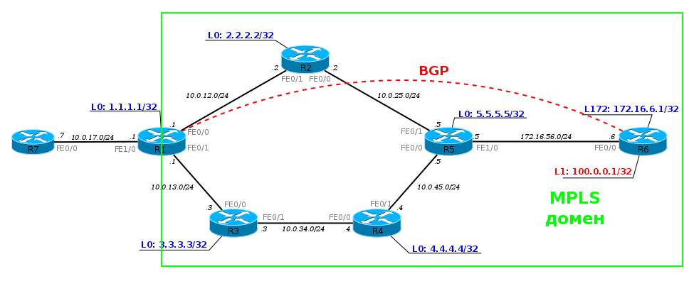
RSVP-TE
LDP is good. It works simply and clearly. But there is such a technology as MPLS TE - Traffic Engineering. And the best route that the LDP can provide is not enough for her.
Traffic management implies that you can direct traffic between nodes as you like, given the various restrictions.
For example, in our network, the client has two points of connection of its nodes - on R1 and on R6. And between them, he asks for a VPN with a guaranteed channel width of 100 Mb / s. But at the same time, we also have regular broadband servers on the network chasing vkontaktik and a dozen other customers who rent a VPN, but they don’t need to reserve a band.
If you do not intervene in this situation, there may be an overload somewhere on R2, and you will not get 100 Mb / s for a dear client.
MPLS TE allows you to go through the entire network from the sender to the recipient and reserve resources on each node. If you are familiar with the concept of IntServ, then yes, it is she who organizes QoS all the way, instead of allowing each router to make a decision for the passing packet.
Actually, the RSVP ( Resource ReSerVation Protocol ) protocol was originally (in 1993) designed to organize IntServ in IP networks. He had to convey QoS information for a specific data flow to each node and force it to reserve resources.
In the first approximation, it works simply.
1) - 5 /. RSVP — Path Message . , IP- , .
2) Path . , .
3) , Path, . , , .
4) 5 / ( ), .
5) Path , Resv , .
6) , Resv, , , .
, .
— RSVP Traffic Engineering , — RSVP TE , MPLS TE.
, LDP — LSR LSP . , , — LSP .
RSVP TE LSP, , , , , , .
MPLS TE . , RSVP TE LSP.
, LSP — , . — LSP.
— LSP, LSR.
, RSVP . .
0) R1 LSP FEC 6.6.6.6/32. Tunnel R1, 6.6.6.6 Traffic Engineering.
1) RSVP Path 6.6.6.6. — Label Request . Path FEC — .
2) Path 6.6.6.6. Etc.
3) Path Egress LSR. , - , Resv. — Label . Egress LSR FEC , .
4) Resv , . LSP, , .
( Path ), ( Resv ).
, Downstream on Demand + Ordered Control. Path , Resv , LSR, .
Stop! , RSVP TE LDP , IGP, « 6.6.6.6».
RSVP TE LDP. RSVP TE , — , .
- , , (link-state), OSPF ISIS.
- , OSPF ISIS . OSPF LSA — Opaque LSA , ISIS — TLV IS Neighbor IP Reachability .
- , Ingress LSR Egress LSR SPF — CSPF ( Constrained Shortest Path First ).
Now more.
Path . — R1, — 6.6.6.6. .
Path FIB , , . , .
Ingress LSR .
, RSVP TE . , ? RSVP , , OSPF ISIS. , RIP, IGRP EIGRP — , — Feasible Successor.
SPF , AD , .
CSPF. , , , - , - , .
RSVP TE CSPF - .
, IGP? . Constraints — . RSVP TE — , , , LSP . , CSPF , . , — , .
OSPF ISIS , , . .
, OSPF 3 LSA:
- Type 9 — link-local scope
- Type 10 — area-local scope
- Type 11 — AS scope
Opaque ( OSPF). LSA, OSPF . . TE ( TED — Traffic Egineering Database ). TE — , - , Opaque LSA.
ISIS. : IS-IS TLV 22 (Extended IS Reachability), 134 (Traffic Engineering router ID), 135 (Extended IP reachability).
, .
0) R1 MPLS TE ISIS (OSPF) TE. . TED. RSVP .
1) , (Traffic Engineering), (6.6.6.6) . LSR CSPF: R1 6.6.6.6 . — (R2, R5, R6).
2) RSVP ERO . R1 RSPV Path, , , ERO. — 6.6.6.6. , Label Request, , FEC (6.6.6.6/32).
ERO — Explicit Route Object — RSVP Path. , .
3) RSVP Path — , ERO. IGP ERO , R2.
4) R2, RSVP Path, , , MPLS FEC 6.6.6.6/32. Path , ERO — R2. , R2. ERO : (R5, R6). R2 Path R5.
5) R5 : , , ERO, Path , ERO — R6.
6) R6, , , . Path, FEC 6.6.6.6 Label Resv.
, , , LSR, .
7) RESV R1 (Ingress LSR), LSP. Resv , Path, .
8) LSP R1 6.6.6.6 . R1 R6. , R6 1.1.1.1 — .
— Path 6.6.6.6, ? — . ERO Ingress LSR Egress LSR — . LSR , . Ingress LSR .
IGP. , OSPF ISIS , . ( ) SPF. .
, IGP (link-state), — - — , , — , , , ABR .
, , MPLS TE — CSPF , — , .
Explicit Path ( ERO). , , LSP — , LSP. Ingress LSR . CSPF .
Explicit Path ? .
, :
Explicit-path: R1, R3, R5.
Explicit Path CSPF, , , Area 0: R1 R3.
, , ERO, Explicit-path — R5. : R1, R2, R3. Path ERO, R3. , - , , - Explicit-path CSPF. (R3, R4, R5), ERO, .
Ingress LSR Egress LSR , ABR.
, Explicit Path , , , LSP , LSP.
, MPLS TE.
, , Link-State IGP. EIGRP, . RIP. And now what? TE?
, Cisco — Verbatim .
Link-State ? TE, CSPF Ingress LSR Egress LSR. . Fine. Explicit Path, ? .
, , CSPF.
. , .
:Router(config-if)# tunnel mpls traffic-eng path-option 1 explicit name <i>test</i> verbatim
CSPF.
, . , , .
RSVP TE
mpls ip LDP. — .
mpls traffic-eng tunnels . TE- RSVP TE:
R1(config)#mpls traffic-eng tunnels :
R1(config)# interface FastEthernet 0/0 R1(config-if)# mpls traffic-eng tunnels R1(config)# interface FastEthernet 0/1 R1(config-if)# mpls traffic-eng tunnels . RSVP .
IGP TE. ISIS:
R1(config)#router isis R1(config-router)# metric-style wide R1(config-router)# mpls traffic-eng router-id Loopback0 R1(config-router)# mpls traffic-eng level-2 — , TE .
LSR-ID, LDP,
ISIS, , TE .
OSPF
R1(config)# mpls traffic-eng area 0
R1(config-router)# mpls traffic-eng router-id Loopback0
R1(config-router)# mpls traffic-eng router-id Loopback0
.
ISIS TE:
LSR-ID, ( TE), .
TED.
ISIS: #show isis database verbose
RSVP .
TE-.
R1(config)# interface Tunnel1 R1(config-if)# ip unnumbered Loopback0 R1(config-if)# tunnel destination 6.6.6.6 R1(config-if)# tunnel mode mpls traffic-eng R1(config-if)# tunnel mpls traffic-eng path-option 10 dynamic — . L2TP, GRE, IPIP , , MPLS TE.
ip unnumbered Loopback0 , Loopback0.
tunnel destination 6.6.6.6 — , , .
tunnel mode mpls traffic-eng — . , .
tunnel mpls traffic-eng path-option 10 dynamic — CSPF , .
, :
%LINEPROTO-5-UPDOWN: Line protocol on Interface Tunnel1, changed state to up ?
R1 Path.
R1-R2.
, ERO Label Request.
— 6.6.6.6, .
Explicit Route:
10.0.12.2 -> 10.0.25.2 -> 10.0.25.5 -> 10.0.56.5 -> 10.0.56.6.
. LSR , Path.
ERO 10.0.12.1, R1 .
Label Request , LSR FEC.
Path — .
Resv , Resv LSR.
R5:
R2-R5.
R2-R5.
Path R6. RSPV Resv:
R5-R6.
, Resv .
Label , FEC.
, R6 0 — Expliit Null. — , MPLS R5 R6 ( EXP, ), R6 , 0 , , .
, (, VPN), RFC 3032 ( ) R5 , , 0. , , .
, , 0 , — . RFC 4182 . 0 .
— PHP. , — 3 — LSR PHP 0. .
R5 Resv R2, R2 R1.
R1-R2.
, , — 16.
=====================
Resv, , , , LSP. ?
.
=====================
Explicit Path
— R1-R3-R4-R5-R6.
: - explicit-path:
R1(config)# ip explicit-path name R1-to-R6-primary R1(cfg-ip-expl-path)# next-address 10.0.13.3 R1(cfg-ip-expl-path)# next-address 10.0.34.4 R1(cfg-ip-expl-path)# next-address 10.0.45.5 R1(cfg-ip-expl-path)# next-address 10.0.56.6 :
R1(config)# Interface Tunnel 1 R1(config-if)# tunnel mpls traffic-eng path-option 5 explicit name R1-to-R6-primary , , — 5 10. explicit-path, - , R1 LSP ( -).
:
interface Tunnel1 ip unnumbered Loopback0 tunnel destination 6.6.6.6 tunnel mode mpls traffic-eng tunnel mpls traffic-eng path-option 5 explicit name R1-to-R6-primary tunnel mpls traffic-eng path-option 10 dynamic no routing dynamic Path, ERO:
, show mpls traffic-eng tunnels :
:
LSP , Loose Strict, FRR make before break, Affinity , MPLS TE.
RSVP-TE .
1: RSVP TE LSP LDP LSP?
, , MPLS . LSP — LSP — .
CR-LSP (ConstRaint-based LSP) — RSVP TE. , CR-LSP .
2: Explicit Path ERO?
Explicit Path, RSVP ERO, Explicit Path. Explicit-Path Egress LSR, RSVP CSPF.
3: LDP (RSVP TE) /, LSP , , IP, MPLS?
RSVP TE Ingress LSR TED Egress LSR, Path, , LSP.
.
LDP, . , R2 LDP FE0/0 ( R5),
1) R1 FEC 6.6.6.6/32. 2: R2, — R3, — R2, LSP R2.
2) R2 , — 1.1.1.1. , . LSP R1 FEC 6.6.6.6/32 .
3) R5 FEC 6.6.6.6/32
, , LSP: {R1-R2, R5-R6}. , . LSP Label Switched, , R1 R2 MPLS, R2 R5 IP, R5 R6 MPLS. LSP FEC 6.6.6.6/32 . , , - MPLS, , , VPN, .
4: , MPLS — - , , MPLS TE-? IGP.
, . But…
, , , , . , . , .
LSP , . TE .
, 40 / 50 / , ? , - QoS , , 3 . 50/, , SLA .
5: - Explicit Null Implicit Null? ?
Need to. , MPLS LSR. «0», Egress LSR , . , TC MPLS, . .
«3» Egress LSR. QoS ( , , DSCP), — , Egress LSR . IP- — IP, - E1, , , lookup LFIB , .
6: FEC LSR ?
:
, FEC .
— ( LSR), FEC .
, FEC , , . .
, MPLS , . LSP , .
LPD over TE. RSVP-TE Traffic Engineering, LDP VPN, .
Egress LSR, MPLS , . . . MPLS VPN.
useful links
- , , MPLS: MPLS for Dummies .
- RFC, :
- . .
- Understanding the Role of FECs in MPLS
- Understanding MPLS Label Stacking
- Understanding Signaling in MPLS Networks
- Understanding MPLS Label Distribution
- Understanding MPLS Explicit and Implicit Null Labels
- Understanding MPLS CSPF
JDima .
.
— .
the gluck
Source: https://habr.com/ru/post/246425/
All Articles