Talk about VPNs? Types of VPN connections. VPN scaling
Colleagues, hello. My name is Vadim Semenov and I want to submit an article on the issue of the scalability of VPNs, and those VPNs that are available for configuration in the usual corporate network of the enterprise, and not from the provider. I hope this article will become a reference material that may be required when designing a network, or when it is upgraded, or in order to refresh the memory of the principle of operation of a particular VPN-on.
At the beginning of the article, the main points of the IPSec protocol stack are described, since the use of this standard will continue to be very frequent. At the end of the paragraph about IPSec, the most frequent causes of the failure of the IPSec channel were included, as well as the main steps to eliminate them.
Below are the VPNs that are available for configuration in the corporate network. Technologies are distributed by the level of channels provided to the client according to the OSI model (Figure 1):

')
Just VPNs for corporate networks will be discussed in this article.
VPN scheme regarding the possibility of multicast skipping and the operation of routing protocols (Fig. 2):

In addition, a structured scheme of VPNs is shown (Fig. 3), which can be provided by the provider, but in this article they are not considered in detail:

The result of the work on the systematization of VPNs and the study of their scalability was the final table, which entered general information on the type of VPN protocol, its features, and the most important thing that needs to be done if you connect another one to existing VPNs.
The table shows the results of the configuration, the study of the received packet format, the configuration of the routing protocol (OSPF) via VPNs, and also examines the scalability of the protocol.
In the process of establishing a connection via IPSec, two participants of a secure channel need to agree on a significant number of parameters: if necessary, they must authenticate each other, generate and exchange shared keys (and through an untrusted environment), determine what traffic to encrypt (from which sender and to which recipient) and also to agree with the help of which protocols to encrypt, and with the help of which - to authenticate. The service information is supposed to be exchanged a lot, isn't it? For this reason, IPSec consists of a protocol stack, the responsibility of which is to ensure the establishment, operation and management of a secure connection. The process of establishing a connection consists of 2 phases: the first phase is established in order to ensure the secure exchange of ISAKMP messages in the second phase. And the ISAKMP (Internet Security Association and Key Management Protocol) is used to negotiate security policies (SA) between the participants of a VPN connection, which is determined by what protocol to encrypt (AES, 3DES, DES), and then authenticate (HMAC SHA, MD5).
Main Mode (6 posts)
After installing IKE SA (i.e., establishing the 1st phase), IPSEC negotiation occurs in quick mode (QM). Messages Mode Main Mode (MM):
- IKE_READY New State = IKE_I_MM1
- IKE_I_MM1 New State = IKE_I_MM2
- IKE_I_MM2 New State = IKE_I_MM3
- IKE_I_MM3 New State = IKE_I_MM4
- IKE_I_MM4 New State = IKE_I_MM5
- IKE_I_MM5 New State = IKE_I_MM6
Aggressive Mode (3 posts)
The initiator places in the first message the proposal for encryption, the authentication protocol of the IKE messages themselves, the lifetime of the keys, the Diffie-Hellman key exchange (DH) message, the session identifier, its authentication.
Command to diagnose this phase on Cisco equipment ** show crypto isakmp sa
Not used in a standard peer-to-peer VPN connection, used for remote connections.
It has two modes:
Xauth (User Authentication)
Mode config (Push Config)
IPsec SAs / SPIs
At this point, the ISAKMP is responsible for exchanging session keys and negotiating security policy (SA) to ensure the confidentiality and integrity of user traffic. In the configuration (in Cisco IOS), the transform-set is responsible for this.
Quick mode
QM does all the things that IPSec SAs / SPIs do with less overhead. By analogy with Aggressive Mode.
Consider an example of the exchange of service messages during the establishment of an IPSec tunnel. A working option.
PHASE 2
And now I propose to consider a couple of examples of IPSec inoperability.
“Old State = IKE_I_MM1 New State = IKE_I_MM1”
Reason # 1
We did not agree on an IKE proposal (proposed by IKE) in Phase 1. 3des is indicated on one side, aes on the other side.
The router displays the following status:
Reason # 2
The ACL on the physical interface blocks ISAKMP traffic.
If transform set on one router is one
... and on the other router another
, then IPSEC SA will not converge (the number of encrypted and decrypted packets will not increase
If the preshared key on the IPSec peers is incorrect
Then there will be an error retransmitting phase 1 MM_KEY_EXCH

Device Configuration:
Health check
SPI is transmitted in the IPSec packet so that when it is received as a pier, in this case HUB, HUB knows which SA (security association) to use, that is, what encryption protocol, what authentication protocol, etc. used as a packet to unscramble. On the HUB there is exactly the same SA with the same SPI.
Successful passing of traffic through VPN on HUB-e
Now add another Spoke, see what changes we need to make
Verify VPN operation
The lack of connectivity before Spoke2 is not surprising - it is necessary to include the internal networks of the new remote office in the Crypto ACL, as a result, in order to ensure connectivity between the Spokes through the HUB, the addition of N N -addressed networks to the Crypto ACL is required.
An example of IPSec configuration of multiple VPNs with remote offices with dynamic or static ip addresses, when each office gets access via the VPN-HUB Internet channel, but all remote networks are located in the routing table and they are connected without using NAT.

In this scheme and in this configuration at remote offices it is set up in the Crypto ACL as the destination network - ip any, i.e. Traffic to any host will be wrapped in a tunnel, and when a new remote office is connected, there is no need to change all other Crypto ACLs in N remote offices.
Regardless of the connection method: Regular IPSec or (running a little ahead, IPSec dynamic IP) in either case we are faced with the task of ensuring accessibility between remote sites. As part of a Regular IPSec and IPSec dynamic IP connection, you need to manually define networks in a crypto ACL, so to reduce configuration on end devices after connecting another remote office, it is possible to go two ways:
The Virtual Tunnel Interface provides a routing interface for terminating IPSec tunnels and an easier way to securely connect remote corporate networks. VTI only supports the transmission through the tunnel of a unicast and multicast, which allows for the operation of dynamic routing protocols without the additional need to encapsulate a packet in GRE (additional 4-bytes). There are two types of virtual tunnel interfaces:
Static virtual interface - is a point-to-point tunnel
Dunicic virtual interface - allows scaling a solution across VPNs by terminating multiple tunnels onto itself from remote Spoke sites, which may have a dynamic IP address. The only drawback is that only remote spoke routers can initiate the establishment of a tunnel (since only they have specified the tunnel destination HUB_ip).
When DVTI is configured, a virtual-template settings template is created on the HUB router, and when a key is exchanged with a remote spoke and a tunnel is established with it, a virtual-access interface is created on the HUB, which is the SVTI tunnel interface for this tunnel.
VTI Features:

OSPF over Static VTI Neighborhood Check
Traffic Selector for Static VTI ip any any, i.e. , , /.
interface Tunnel0
ip address 10.1.1.254 255.255.255.0
ip ospf mtu-ignore
OSPF Neighbor MTU . neighbor MTU DBD , MTU , .
Spoke2 Tunnel (HUB-Spoke2), .

Dynamic VTI HUB, Static VTI spoke-. Dynamic VTI crypto map-.
Spoke-:
OSPF :
Tunnel Spoke, ipsec . :
.
Easy VPN VPN- , IPSec VPN- VPN HUB-. (ISAKMP) 1.5. vpn- IP-, DNS-, ACL split tunnel. Cisco VPN Client.
Easy VPN Remote [1] :
:
Cisco Easy VPN Remote transform set (ESP-DES and ESP-3DES) transform-set, (ESP-NULL ESP-SHA-HMAC and ESP-NULL ESP-MD5-HMAC)
VPN- () NAT/PAT Cisco Easy VPN Remote, NAT- ( )

VPN- () NAT/PAT- ,
ip outside nat (ip nat inside ) ACL!
, NAT , ACL
, . ,
Gre , (OSPF, EIGRP) IPv6 . IP ( 47) GRE . GRE , Cisco, RFC 2784.
GRE point-to-point . () .

OSPF
:
GRE over IPSec
:

OSPF over GRE over IPSec
OSPF ( network type broadcast)
DMVPN implements multipoint GRE architecture, allowing you to use, firstly, one address space for all vpn remote offices, secondly, to pass through the tunnel a large list of third-party protocols, as well as multicast, and thirdly, to establish dynamically tunnels between regional remote sites in case of traffic between them. However, there is one thing, this technology is only realizable on a mono-vendor network on Cisco.

Configure the HQ router as DMVPN HUB, Spoke 1 as DMVPN Client
DMVPN operation check
Check whether the tunnel is established to DMVPN HUBa.
Please note that NBMA address is the real address of HUBa.
Creating a dynamic GRE tunnel from a remote office Spoke1 to Spoke2
At the start of the boot, the Spoke 1 had only 1 tunnel to HUB. When generating traffic (ping) to Spoke2, a tunnel to Spoke2 was immediately created.
At the moment, the network diagram (Fig. 13) will look like this:

Making the settings via DMVPN and including the common network for VPN 10.5.5.0 in the OSPF process - we will see how OSPF on the HUB will establish contiguous relationships first with Spoke1 until it receives a hello packet from Spoke2, after that the relationships collapse with Neighbor Down: Adjacency error forced to reset, since the default interface Tunnel is set as the point-to-point interface. For OSPF to work correctly, you need to set the network type as broadcast. If you set the broadcast only on HUBe, then the neighborhood will be established, but there will be no routes through OSPF on Spok-a, so you need to set the broadcast on both the HUB and Spoke-ah.
Below are the tables of OSPF behavior depending on the selected network type value.
Turn off on the HUBe split-horizon
Let's get rid of HUB as an intermediate device in the connectivity of Spoke1 <-> Spoke2
PPTP became a joint development of Microsoft, 3Com, Ascend Communication consortia. Well scalable protocol. It can be used to connect offices as a point-to-point, but most of all is suitable for organizing a remote connection on a client-server architecture. It is enough to configure the central PPTP VPN HUB, and remote users connect through the PPTP client, which is implemented in all Windows OS, including MacOS and Linux distributions.
There are cryptographic problems in the MSCHAPv2 authentication protocol [https://technet.microsoft.com/ru-ru/library/security/2743314.aspx], so in most cases even L2TP over IPSec is recommended instead of PPTP on Windows .
Only one Microsoft Point-to-Point Encryption protocol (128-bit key) is used as encryption means, and MSCHAPv2, PEAP (recommended) is used as authentication.
PPTP in its work establishes 2 sessions: a PPP session using the GRE protocol and a TCP connection on port 1723 for serving the PPTP session.
Establishing a TCP session before establishing a PPP connection

PPP package format (fig.15)

Checking the established PPTP connections.
User cisco2 is logged in and session is established.
The user is given an ip address from the DHCP Pool and created virtual-access
If there is a task for a specific PPTP client to issue an IP address belonging only to it, then you can resort to creating a TXT file listing all PPTP clients.
Setup on the router:
The TXT file itself is static2.txt.
L2TP is an IETF standard that incorporates the best of Cisco's L2F protocol and Microsoft's PPTP. It does not offer data protection tools, so it is often used with IPSec.
L2TP is one of the few representatives of VPN protocols (also available for implementation in a corporate network), which pseudowire technology can offer - forwarding native vlan via L3 network. The pseudowire technology only supports L2TP version 3. In addition, L2TPv3 supports the following L2 protocols, the data (payloads) of which can be transparently transmitted through the pseudo-tunnel L2TPv3:
The main difference between L2TPv3 and L2TPv2 is that L2TPv3 can tunnel different types of traffic (see above), while v2 only PPP.
L2TPv3 uses two types of messages:
L2TPv3 signaling messages and data messages can be transferred via IP (protocol ID 115), i.e. L2TPv3 uses less overhead
L2TPv2 encapsulates data in IP / UDP (UDP port 1701).
The L2TP architecture, as well as the PPTP architecture, uses the following concepts:
The protocol operation model for L2TPv3 LNS is LNS, and for L2TPv2 LAC is LNS (for details, see below).
Let's create a pseudowire between R5 in the Central Office and in R9 in the regional office, thereby expanding the network 192.168.1.x / 24 to the regional office.

Session establishment check:
R7 is now available without routing protocols:
Neighborhood established by default, including the network 192.168.1.0 on R7 and R10
Disadvantages:
If L2TP is created on a router as in our example, then the following L2 PDUs will not go through pseudowire connections: CDP, STP, VTP, LLDP. To tunnel such protocols, you must create an L2TPv3 tunnel on the L3 switch.
Big minus - we have to remove the ip address on the interface of the router, which serves as the default route for all other stations. As a result, our PCs remain without communication with other networks.
L2 VPN works in two modes:
Mandatory tunnel mode refers to provider-provisioning and L2F, PPTP, L2TP protocols operate in this mode. In mandatory tunnel mode via L2TP, remote users connect to the LAC via a normal PPP connection, the LAC terminates them and tunnels the PPP session to the LNS. Moreover, the remote user does not even suspect about L2TP.

In a voluntary / client initiated tunnel, the remote host acts as a LAC, that is, it negotiates and establishes an L2TP session directly with the LNS.

In our example, Cisco R9 (44.1.1.9) will act as a LAC and establish an L2TP connection with Cisco R5 in the data center (55.1.1.1), which will act as an LNS.


The service channel is established, the channel for data ( PPP frames) is now established .
It is worth noting that a set of client sessions can take place on one established tunnel.

To set up a session for LAC data, it sends an ICRQ (Call-Request), if there are enough resources on the LNS, then the LNS responds with an ICRP (Call-Reply) message. To complete the session establishment - LAC sends ICCN Incoming-Call-Connected.
In our example, one tunnel was formed between the LAS and the LNS and one user session.
The L2TP configuration in the voluntary tunnel mode is very similar in configuration with the mandatory tunnel mode. The difference in setting up a VPDN group is as follows:
interface virtual-ppp, interface Dialer. «AS IS».
L2TPv2 interface virtual-ppp

(LAC) L2TP HUBe (LNS)
L2TPv2

Overhead UDP (8) + L2TPv2 (8) + PPP (4 ) +IPv4 (20 ) = 40
LSA OSPF L2TPv2
, , overhead.

Overhead UDP (8) + L2TPv2 (8) + PPP (4 ) +IPv4 (20 ) = 40

L2TPv3 , VPN HUB- .
L2TPv3 LNS
L2TPv3 LAC
L2TPv3

Overhead L2TPv3 (4) + HDLC (4) = 8
(LAC) L2TP HUBe (LNS)
L2TP , IPSec. L2TP , , PPP . L2TPv2, IP/UDP , ACL UDP 1701. IPSec , , ( ), IP ( ).

:

(LAC) L2TP HUBe (LNS)
L2TPv2 over IPSec

IP | ESP header | UDP | L2TP | PPP | ESP trailer | Auth trailer
Overhead ESP_header (8) + UDP (8) + L2TPv2 (8) + PPP (4 ) + ESP_trailer (min 2) + SHA_auth (160 = 20 ) = 50 a
OSPF , hello - 10 . OSPF .
LNS, .. L2TPv2 HUB – PPP CHAP . , :
LAC

LNS 2
OSPF L2TPv2
L2TPv2 – . OSPF loopback-:
OSPF
OSPF, ( L2TP HUBe) – ip ppp .
IP , 1 , 192.168. 25.0 /24 interface virtual-ppp VPN HUBa, - 192.168. 25.16 /29 , VPN HUB vitual-ppp :
HUB (conf)#ip route 192.168.25.16 255.255.255.248 16.16.16.16 (<- 16.16.16.16 virtual-ppp , VPN HUBa :
, , . , , , , . , «» , , ! .
PS
: , VPN-, — , VPN- .
.
At the beginning of the article, the main points of the IPSec protocol stack are described, since the use of this standard will continue to be very frequent. At the end of the paragraph about IPSec, the most frequent causes of the failure of the IPSec channel were included, as well as the main steps to eliminate them.
Types of VPN connections
Below are the VPNs that are available for configuration in the corporate network. Technologies are distributed by the level of channels provided to the client according to the OSI model (Figure 1):
')
Just VPNs for corporate networks will be discussed in this article.
VPN scheme regarding the possibility of multicast skipping and the operation of routing protocols (Fig. 2):
In addition, a structured scheme of VPNs is shown (Fig. 3), which can be provided by the provider, but in this article they are not considered in detail:
The result of the work on the systematization of VPNs and the study of their scalability was the final table, which entered general information on the type of VPN protocol, its features, and the most important thing that needs to be done if you connect another one to existing VPNs.
The table shows the results of the configuration, the study of the received packet format, the configuration of the routing protocol (OSPF) via VPNs, and also examines the scalability of the protocol.
VPN table
| VPN type | HUB Setup | Spoke Setup | Configure HUB when adding a new Spoke | Spoke setup when adding another new Spoke | Using dynamic routing protocols OSPF, EIGRP | Special features |
| Regular IPSec (crypto map) | isakmp Crypto-map | isakmp Crypto-map | Yes: isakmp crypto-map: set peer, transform-set, crypto ACL | Yes: To ensure connectivity between the Spokees, it is necessary to add routes of the new Spoke in the crypto ACL of all existing Spokees. | Not | Convenient in case of Spoke <5-10. To ensure connectivity between the Spokes through HUB, it is required to add N networks on N spokes to crypto ACL Extremely unscalable. |
| Regular IPSec (Profile) | isakmp profile, IPSec Profile, rypto-map | isakmp profile, IPSec Profile, rypto-map | Yes: crypto-map: set peer, crypto ACL | Yes: Adding new routes to crypto ACL | Not | Extremely non-scalable. Less configuration due to the combination of typical settings in profile. |
| Regular IPSec (Profile, Static VTI) | isakmp profile, IPSec Profile, VTI (Virtual Tunnel Interface) | isakmp IPSec Profile, VTI (Virtual Tunnel Interface) | Yes: isakmp new VTI (Virtual Tunnel Interface) | Yes static route to networks beats. office | Yes | In SVTI configuration without IGP - extremely non-scalable. For each Spoke on SVTI. N spoke - N VTI and its own subnet. Spoke requires adding routes to remote Spoke's. Skips multicast! By default, there is only one IPSec SA for each SVTI with traffic selector “IP any any.” There is no crypto ACL command. The networks that are defined via the static route on the SVTI are wrapped in the tunnel. |
| Regular IPSec (Profile, Static VTI and IGP) | isakmp IPSec Profile, VTI (Virtual Tunnel Interface) | isakmp IPSec Profile, VTI (Virtual Tunnel Interface) | Yes: isakmp new VTI (Virtual Tunnel Interface) | Not | Yes | Not scalable. For each Spoke on SVTI. N spoke - N VTI and its own subnet. Routes from IGP fall into the tunnel. |
| IPSec with dynamic IP (Dynamic VTI and Static VTI and IGP) | keyring, isakmp policy, isakmp profile, ipsec profile, loopback for unnumbered interface (required), Virtual-Template type tunnel | keyring, isakmp policy, isakmp profile, ipsec profile, loopback for unnumbered interface Static VTI | Not | Not | Yes | Very scalable. All spoke and hub are in the same network! Dynamic VTI (DVTIs) is also a point-to-point interface. In point-to-multipoint mode, OSPF adjacency is not established. Using Unnumbered IP as DVTI address is required |
| Easy VPN | AAA - for client authorization Isakmp, isakmp policy, isakmp profile, ipsec profile, interface, Virtual-Template type tunnel DHCP for clients | Minimum IPsec client configuration, indicating the VPN server, VPN group, user for aaa, Indication of internal and external interfaces. | Not | Not | Yes | Scalable. If NAT / PAT was previously configured, then this configuration should be deleted before implementing EASY VPN. There are features in the transform-set setup. |
| GRE | Interface Tunnel, Static route | Interface Tunnel, Static route | Yes Int tunnel Static route | Yes Static route | Yes | Not scalable. Forms a P2P link, each tunnel has its own subnet. Perfect for tunneling IGP protocols. |
| IGP over GRE | Interface Tunnel, Static route | Interface Tunnel, Static route | Yes Int tunnel | Not | Yes | Not scalable. Each tunnel has its own subnet. IGP protocols work through a tunnel with default settings. |
| DMVPN (proprietary) | DMVPN phase 1 - mGRE only DMVPN phase 2 - setting up the ipsec profile to protect traffic | Minimum: DMVPN phase 1 - mGRE only DMVPN phase 2 - setting up the ipsec profile to protect traffic | Not | Not: when adding a new spoke - the tunnel to it is built automatically | Yes: EIGRP on HUB turn off the split of the horizon and save yourself as next-hop in route announcements | The most scalable protocol. GRE multipoint. Tunnels between remote offices are dynamically created. |
| PPTP | Vpdn-group, interface virtual-template, IP local pool, username / password for authorization, static route to the office network | service internal (to enable client pptp settings), vpdn-group, interface dialer, dialer-list, static route to center networks., Del. office | Yes Static route for internal networks for PPTP client | Yes Static route for new internal networks for a new PPTP client | Yes | Scalable with restrictions. Morally obsolete protocol, vulnerabilities in cryptography in the MSCHAPv2 authorization protocol. Most often used to create remote access. Supported by many popular versions of Windows. Isp only one protocol for encryption -MPPE (RC4 with a 128-bit key). It supports multicast, because PPP are encapsulated in GRE. |
| IGP over PPTP | Vpdn-group, interface virtual-template, IP local pool, username / password for authentication, IGP protocol (router ospf process) | service internal (to enable client pptp settings), vpdn-group, interface dialer, dialer-list, IGP protocol (router ospf process) | Not | Not | Yes | Scalable with restrictions. It supports multicast, because PPP are encapsulated in GRE. Morally obsolete protocol -> L2TP over IPSec alternative |
| L2TPv3 xconnect | pseudowire-class xconnect | pseudowire-class xconnect | Yes xconnect | Not | Yes | Not scalable. Great for posting native L2 vlan over IP network. But, you must have a backup gateway by default. Creating xconnect on the router interface, we have to remove the IP address from its interface, thereby removing the default route for all devices within this network. |
| L2TPv2 / v3 | aaa new-model, username to authorize L2TP peer, VPDN-group, interface virtual-template, static route to networks beats. office | username for authorization L2TP HUBa, interface virtual-ppp, pseudowire class, static route to center networks., Del. office | Yes: static route to remote office internal networks | Yes: static route to remote office internal networks | Yes | Scalable. L2TPv3 provides great benefits by allowing you to not only encapsulate PPP traffic, like L2TPv2, but also send a VLAN tag and also encapsulate HDLC, Frame Relay. |
| IGP over L2TPv2 / v3 | aaa new-model, username to authorize L2TP peer, VPDN-group, interface virtual-template, IGP (router ospf process) | username for authorization L2TP HUBa, interface virtual-ppp, pseudowire class, IGP (router ospf process) | Not | Not | Yes | Very scalable. Allows you to configure the routing protocols "by default", the connection of remote offices via L2TPv2 / v3 HUB (at the central office). |
The establishment of IPSec, messages, modes of operation.
In the process of establishing a connection via IPSec, two participants of a secure channel need to agree on a significant number of parameters: if necessary, they must authenticate each other, generate and exchange shared keys (and through an untrusted environment), determine what traffic to encrypt (from which sender and to which recipient) and also to agree with the help of which protocols to encrypt, and with the help of which - to authenticate. The service information is supposed to be exchanged a lot, isn't it? For this reason, IPSec consists of a protocol stack, the responsibility of which is to ensure the establishment, operation and management of a secure connection. The process of establishing a connection consists of 2 phases: the first phase is established in order to ensure the secure exchange of ISAKMP messages in the second phase. And the ISAKMP (Internet Security Association and Key Management Protocol) is used to negotiate security policies (SA) between the participants of a VPN connection, which is determined by what protocol to encrypt (AES, 3DES, DES), and then authenticate (HMAC SHA, MD5).
Mode of operation IKE (Internet Key Exchange):
IKE Phase 1
- (optional) peer authentication
- IKE SA negotiation between peers
Main Mode (6 posts)
- [First exchange] Beginning of approvals begins with peering to each other offers of supported encryption, authentication protocols of the IKE messages themselves, the lifetime of the security associations. A feast chooses the proposed SA and sends them to the proposed feast. These settings are defined in the ISAKMP Policy
- [Second exchange] Generate shared shared keys through public key exchange via Diffie-Hellman. Further messaging occurs already encrypted messages.
- [Third exchange] Messaging for ISAKMP session authentication (IKE_I_MM4 )
After installing IKE SA (i.e., establishing the 1st phase), IPSEC negotiation occurs in quick mode (QM). Messages Mode Main Mode (MM):
- IKE_READY New State = IKE_I_MM1
- IKE_I_MM1 New State = IKE_I_MM2
- IKE_I_MM2 New State = IKE_I_MM3
- IKE_I_MM3 New State = IKE_I_MM4
- IKE_I_MM4 New State = IKE_I_MM5
- IKE_I_MM5 New State = IKE_I_MM6
Aggressive Mode (3 posts)
The initiator places in the first message the proposal for encryption, the authentication protocol of the IKE messages themselves, the lifetime of the keys, the Diffie-Hellman key exchange (DH) message, the session identifier, its authentication.
Command to diagnose this phase on Cisco equipment ** show crypto isakmp sa
IKE Phase 1.5
Not used in a standard peer-to-peer VPN connection, used for remote connections.
It has two modes:
Xauth (User Authentication)
- Additional user authentication within the IKE protocol. For this, the Extended Authentication protocol is used.
Mode config (Push Config)
- Additional information is transmitted to the client about the IP address, mask, DNS servers, etc.
IKE Phase 2
IPsec SAs / SPIs
At this point, the ISAKMP is responsible for exchanging session keys and negotiating security policy (SA) to ensure the confidentiality and integrity of user traffic. In the configuration (in Cisco IOS), the transform-set is responsible for this.
Quick mode
QM does all the things that IPSec SAs / SPIs do with less overhead. By analogy with Aggressive Mode.
Consider an example of the exchange of service messages during the establishment of an IPSec tunnel. A working option.
| ISAKMP: (1007): Old State = IKE_I_MM6 New State = IKE_I_MM6 * Sep 3 08: 59: 27.539: ISAKMP: (1007): Input = IKE_MESG_INTERNAL, IKE_PROCESS_COMPLETE * Sep 3 08: 59: 27.543: ISAKMP: (1007): Old State = IKE_I_MM6 New State = IKE_P1_COMPLETE |
PHASE 2
| * Sep 3 08: 59: 27.559: ISAKMP: (1007): beginning Quick Mode exchange, M-ID of 2551719066 * Sep 3 08: 59: 27.563: ISAKMP: (1007): QM Initiator gets spi * Sep 3 08: 59: 27.575: ISAKMP: (1007): sending packet to 192.168.0.2 my_port 500 peer_port 500 (I) QM_IDLE * Sep 3 08: 59: 27.575: ISAKMP: (1007): Sending an IKE IPv4 Packet . * Sep 3 08: 59: 27.583: ISAKMP: (1007): Node 2551719066, Input = IKE_MESG_INTERNAL, IKE_INIT_QM * Sep 3 08: 59: 27.587: ISAKMP: (1007): Old State = IKE_QM_READY New State = IKE_QM_I_QM1 * Sep 3 08: 59: 27.803: ISAKMP: (1007): Checking IPSec proposal 1 * Sep 3 08: 59: 27.803: ISAKMP: transform 1, ESP_AES * Sep 3 08: 59: 27.807: ISAKMP: attributes in transform : * Sep 3 08: 59: 27.807: ISAKMP: encaps is 1 (Tunnel) * Sep 3 08: 59: 27.811: ISAKMP: SA life type in seconds * Sep 3 08: 59: 27.815: ISAKMP: SA life duration (basic) of 3600 * Sep 3 08: 59: 27.815: ISAKMP: SA life type in kilobytes * Sep 3 08: 59: 27.819: ISAKMP: SA life duration (VPI) of 0x0 0x46 0x50 0x0 * Sep 3 08: 59: 27.827: ISAKMP: authenticator is HMAC-SHA * Sep 3 08: 59: 27.827: ISAKMP: key length is 128 * Sep 3 08: 59: 27.831: ISAKMP: (1007): atts are acceptable. * Sep 3 08: 59: 27.855: ISAKMP: (1007): Old State = IKE_QM_I_QM1 New State = IKE_QM_IPSEC_INSTALL_AWAIT ISAKMP: (1007): Old State = IKE_QM_IPSEC_INSTALL_AWAIT New State = IKE_QM_PHASE2_COMPLETE |
And now I propose to consider a couple of examples of IPSec inoperability.
Case1
“Old State = IKE_I_MM1 New State = IKE_I_MM1”
Reason # 1
We did not agree on an IKE proposal (proposed by IKE) in Phase 1. 3des is indicated on one side, aes on the other side.
| Error while processing SA request: Failed to initialize SA * Sep 3 08: 36: 38.239: ISAKMP: Error while processing KMI message 0, error 2. * Sep 3 08: 36: 38.287: ISAKMP: (0): retransmitting phase 1 MM_NO_STATE ... * Sep 3 08: 40: 38.307: ISAKMP (0): incrementing error on ret 5, retransmit phase 1 * Sep 3 08: 40: 38.307: ISAKMP: (0): retransmitting phase 1 MM_NO_STATE * Sep 3 08: 37: 08.339: ISAKMP: (0): deleting SA reason "Death by retransmission P1" state (I) MM_NO_STATE (peer 192.168.0.2) * Sep 3 08: 41: 08.359: ISAKMP: (0): Input = IKE_MESG_INTERNAL, IKE_PHASE1_DEL * Sep 3 08: 41: 08.359: ISAKMP: (0): Old State = IKE_I_MM1 New State = IKE_DEST_SA |
The router displays the following status:
| R7 # sh crypto isakmp sa IPv4 Crypto ISAKMP SA dst src state conn-id status 192.168.0.2 192.168.0.1 MM_NO_STATE 0 ACTIVE |
Reason # 2
The ACL on the physical interface blocks ISAKMP traffic.
Case2
If transform set on one router is one
| R7 # sh run | i transform crypto ipsec transform-set TRANSFORM esp-aes esp-md5-hmac |
... and on the other router another
| R10 # sh run | i transform crypto ipsec transform-set TRANSFORM esp-aes esp-sha-hmac |
, then IPSEC SA will not converge (the number of encrypted and decrypted packets will not increase
| * Sep 3 08: 56: 08.551: ISAKMP: (1006): IPSec policy invalidated proposal with error 256 * Sep 3 08: 56: 08.559: ISAKMP: (1006): phase 2 SA policy not acceptable! (local 192.168.0.1 remote 192.168.0.2) * Sep 3 08: 56: 08.563: ISAKMP: set new node -1456368678 to QM_IDLE * Sep 3 08: 56: 08.567: ISAKMP: (1006): Sending NOTIFY PROPOSAL_NOT_CHOSEN protocol 3 spi 1785687224, message ID = 2838598618 * Sep 3 08: 56: 08.575: ISAKMP: (1006): sending packet to 192.168.0.2 my_port 500 peer_port 500 (I) QM_IDLE * Sep 3 08: 56: 08.579: ISAKMP: (1006): Sending an IKE IPv4 Packet. * Sep 3 08: 56: 08.583: ISAKMP: (1006): purging node -1456368678 * Sep 3 08: 56: 08.587: ISAKMP: (1006): deleting node 1350414148 error TRUE reason " QM rejected " * Sep 3 08: 56: 08.591: ISAKMP: (1006): Node 1350414148, Input = IKE_MESG_FROM_PEER, IKE_QM_EXCH * Sep 3 08: 56: 08.595: ISAKMP: (1006): Old State = IKE_QM_READY New State = IKE_QM_READY |
Case3
If the preshared key on the IPSec peers is incorrect
| R7 #sh run | i isakmp key crypto isakmp key cisco123 address 172.16.1.2 |
| R10 #sh run | i isakmp key crypto isakmp key cisco address 0.0.0.0 0.0.0.0 |
Then there will be an error retransmitting phase 1 MM_KEY_EXCH
| * Sep 3 09: 14: 30.659: ISAKMP: (1010): retransmitting phase 1 MM_KEY_EXCH ... * Sep 3 09: 14: 30.663: ISAKMP (1010): incrementing error on ret 5, retransmit phase 1 * Sep 3 09: 14: 30.663: ISAKMP: (1010): retransmitting phase 1 MM_KEY_EXCH * Sep 3 09: 14: 30.663: ISAKMP: (1010): sending packet to 192.168.0.2 my_port 500 peer_port 500 (I) MM_KEY_EXCH * Sep 3 09: 14: 30.663: ISAKMP: (1010): Sending an IKE IPv4 Packet. * Sep 3 09: 14: 30.711: ISAKMP (1010): received packet from 192.168.0.2 dport 500 sport 500 Global (I) MM_KEY_EXCH * Sep 3 09: 14: 30.715: ISAKMP: (1010): phase 1 packet is a duplicate of a previous packet. * Sep 3 09: 14: 50.883: ISAKMP: (1011): retransmitting due to retransmit phase 1 * Sep 3 09: 14: 51.383: ISAKMP: (1011): retransmitting phase 1 MM_KEY_EXCH ... * Sep 3 09: 14: 51.387: ISAKMP: (1011): peer does not paranoid keepalives. * Sep 3 09: 14: 51.387: ISAKMP: (1011): deleting SA reason "Death by retransmission P1" state ® MM_KEY_EXCH (peer 192.168.0.2) * Sep 3 09: 14: 51.395: ISAKMP: (1011): Input = IKE_MESG_INTERNAL, IKE_PHASE1_DEL |
Regular IPSec
Setup via Crypto map
Device Configuration:
| Hub | Spoke1 |
| Configure the first IPSec phase for session key exchange: crypto isakmp policy 1 hash md5 authentication pre-share group 5 crypto isakmp key cisco123 address 172.16.1.2 ! Setting up the second phase of IPSec c setting the encryption algorithm and authentication crypto ipsec transform-set Trans_HUB1_SP1 esp-aes 256 esp-md5-hmac ! crypto map HUB_SPOKEs 1 ipsec-isakmp set peer 172.16.1.2 set transform-set Trans_HUB1_SP1 match address TO_Spoke1 reverse-route static ! | crypto isakmp policy 1 hash md5 authentication pre-share group 5 crypto isakmp key cisco123 address 192.168.1.1 ! crypto ipsec transform-set Trans_SP1_HUB1 esp-aes 256 esp-md5-hmac ! crypto map SP1_HUB 1 ipsec-isakmp set peer 192.168.1.1 set transform-set Trans_SP1_HUB1 match address TO_HUB reverse-route static ! |
| Configuring route wrapping in a tunnel | |
| ip access-list extended TO_Spoke1 permit ip 10.0.0.0 0.0.0.255 1.1.1.0 0.0.0.255 ! Interface Ethernet0 / 0 ip address 192.168.1.1 255.255.255.0 crypto map HUB_SPOKEs ! | ip access-list extended TO_HUB permit ip 1.1.1.0 0.0.0.255 10.0.0.0 0.0.0.255 ! Interface Ethernet0 / 0 ip address 172.16.1.1 255.255.255.0 crypto map SP1_HUB ! |
Health check
| HUB #ping 1.1.1.1 source 10.0.0.1 . !!!! Success rate is 80 percent (4/5), round-trip min / avg / max = 4/4/5 ms | Spoke1 #ping 10.0.0.1 source 1.1.1.1 . !!!! Success rate is 80 percent (4/5), round-trip min / avg / max = 4/4/5 ms |
| VPN Convergence Check: | |
| Successful key exchange: Spoke1 #show crypto isakmp sa IPv4 Crypto ISAKMP SA dst src state conn-id status 192.168.1.1 172.16.1.2 QM_IDLE 1007 ACTIVE Successful passing of traffic through VPN: Spoke1 #show crypto ipsec sa interface: Ethernet0 / 0 Crypto map tag: SP1_HUB, local addr 172.16.1.2 protected vrf: (none) local ident (addr / mask / prot / port): (1.1.1.0/255.255.255.0/256/0) remote ident (addr / mask / prot / port): (10.0.0.0/255.255.255.0/256/0) current_peer 192.168.1.1 port 500 PERMIT, flags = {origin_is_acl,} # pkts encaps: 4 , #pkts encrypt: 4, #pkts digest: 4 # pkts decaps: 4 , #pkts decrypt: 4, #pkts verify: 4 #pkts compressed: 0, #pkts decompressed: 0 #pkts not compressed: 0, #pkts compr. failed: 0 #pkts not decompressed: 0, #pkts decompress failed: 0 #send errors 0, #recv errors 0 local crypto endpt .: 172.16.1.2, remote crypto endpt .: 192.168.1.1 path mtu 1500, ip mtu 1500, ip mtu idb Ethernet0 / 0 current outbound spi: 0xA7424886 (2806139014) PFS (Y / N): N, DH group: none | |
SPI is transmitted in the IPSec packet so that when it is received as a pier, in this case HUB, HUB knows which SA (security association) to use, that is, what encryption protocol, what authentication protocol, etc. used as a packet to unscramble. On the HUB there is exactly the same SA with the same SPI.
Successful passing of traffic through VPN on HUB-e
| Hub #sho crypto ipsec sa interface: Ethernet0 / 0 Crypto map tag: HUB_SPOKEs, local addr 192.168.1.1 protected vrf: (none) local ident (addr / mask / prot / port): (10.0.0.0/255.255.255.0/256/0) remote ident (addr / mask / prot / port): (1.1.1.0/255.255.255.0/256/0) current_peer 172.16.1.2 port 500 PERMIT, flags = {origin_is_acl,} #pkts encaps: 4, #pkts encrypt: 4, #pkts digest: 4 #pkts decaps: 4, #pkts decrypt: 4, #pkts verify: 4 #pkts compressed: 0, #pkts decompressed: 0 #pkts not compressed: 0, #pkts compr. failed: 0 #pkts not decompressed: 0, #pkts decompress failed: 0 #send errors 0, #recv errors 0 local crypto endpt .: 192.168.1.1, remote crypto endpt .: 172.16.1.2 path mtu 1500, ip mtu 1500, ip mtu idb Ethernet0 / 0 current outbound spi: 0x10101858 (269490264) PFS (Y / N): N, DH group: none inbound esp sas: spi: 0xA7424886 (2806139014) transform: esp-256-aes esp-md5-hmac, in use settings = {Tunnel,} conn id: 19, flow_id: SW: 19, sibling_flags 80000040, crypto map: HUB_SPOKEs sa timing: remaining key lifetime (k / sec): (4360017/2846) IV size: 16 bytes replay detection support: Y Status: ACTIVE (ACTIVE) |
Now add another Spoke, see what changes we need to make
| Setup on HUB | Setup on the new Spoke |
| HUB # crypto isakmp policy 1 hash md5 authentication pre-share group 5 crypto isakmp key cisco123 address 172.16.1.2 crypto isakmp key cisco456 address 172.16.2.3 ! ! crypto ipsec transform-set Trans_HUB1_SP1 esp-aes 256 esp-md5-hmac ! crypto map HUB_SPOKEs 1 ipsec-isakmp set peer 172.16.1.2 set peer 172.16.2.3 set transform-set Trans_HUB1_SP1 match address TO_Spokes reverse-route static ! ip access-list extended TO_Spokes permit ip 10.0.0.0 0.0.0.255 1.1.1.0 0.0.0.255 permit ip 10.0.0.0 0.0.0.255 2.2.2.0 0.0.0.255 those. to add N spoke, you need 3 N additional lines | The setup is the same as on the first Spoke1 (including the internal network correction in the ACL) Spoke2 # crypto isakmp policy 1 hash md5 authentication pre-share group 5 crypto isakmp key cisco456 address 192.168.1.1 ! ! crypto ipsec transform-set Trans_SP2_HUB1 esp-aes 256 esp-md5-hmac ! crypto map SP2_HUB 1 ipsec-isakmp set peer 192.168.1.1 set transform-set Trans_SP2_HUB1 match address TO_HUB reverse-route static ! ip access-list extended TO_HUB permit ip 2.2.2.0 0.0.0.255 10.0.0.0 0.0.0.255 |
Verify VPN operation
| Check availability of a second remote office: HUB # ping 2.2.2.2 source 10.0.0.1 . !!!! Success rate is 80 percent (4/5), round-trip min / avg / max = 4/4/5 ms An additional key exchange session with the second Spoke now appeared on HUB: Hub sho crypto isakmp sa IPv4 Crypto ISAKMP SA dst src state conn-id status 192.168.1.1 172.16.2.3 QM_IDLE 1009 ACTIVE 192.168.1.1 172.16.1.2 QM_IDLE 1008 ACTIVE However, there is no connection between the offices (even through HUB). Spoke1 # ping 2.2.2.2 source 1.1.1.1 ..... Success rate is 0 percent (0/5) |
The lack of connectivity before Spoke2 is not surprising - it is necessary to include the internal networks of the new remote office in the Crypto ACL, as a result, in order to ensure connectivity between the Spokes through the HUB, the addition of N N -addressed networks to the Crypto ACL is required.
Alternative. Multiple Crypto map.
An example of IPSec configuration of multiple VPNs with remote offices with dynamic or static ip addresses, when each office gets access via the VPN-HUB Internet channel, but all remote networks are located in the routing table and they are connected without using NAT.
| HUB # crypto ipsec transform-set 3DES-MD5 esp-3des esp-md5-hmac mode tunnel ! crypto ipsec profile Spokes_VPN_Profile set security-association lifetime seconds 86400 set transform-set 3DES-MD5 set reverse-route distance 1 reverse-route ! crypto dynamic-map hq-vpn 30 set profile Spokes_VPN_Profile match address VPN33-32-TRAFFIC crypto dynamic-map hq-vpn 3348 set profile Spokes_VPN_Profile match address VPN3348-TRAFFIC crypto dynamic-map hq-vpn 50 set profile Spokes_VPN_Profile match address VPN33-64-TRAFFIC ! crypto map VPN 1 ipsec-isakmp dynamic hq-vpn ! interface GigabitEthernet1 / 0 ip address 55.1.1.5 255.255.255.0 <omitted ...> crypto map VPN ! ip access-list extended VPN33-32-TRAFFIC permit ip any 192.168.33.32 0.0.0.15 ip access-list extended VPN33-48-TRAFFIC permit ip any 192.168.33.48 0.0.0.15 ip access-list extended VPN33-64-TRAFFIC permit ip any 192.168.33.64 0.0.0.15 | Spoke # crypto ipsec transform-set 3DES-MD5 esp-3des esp-md5-hmac mode tunnel ! crypto map VPN 1 ipsec-isakmp set peer 55.1.1.5 set transform-set 3DES-MD5 match address TO_HUB reverse-route static ! interface FastEthernet0 / 0 ip address negotiated <omitted ...> crypto map VPN ! ip access-list extended TO_HUB permit ip 192.168.33.32 0.0.0.15 any |
In this scheme and in this configuration at remote offices it is set up in the Crypto ACL as the destination network - ip any, i.e. Traffic to any host will be wrapped in a tunnel, and when a new remote office is connected, there is no need to change all other Crypto ACLs in N remote offices.
Regardless of the connection method: Regular IPSec or (running a little ahead, IPSec dynamic IP) in either case we are faced with the task of ensuring accessibility between remote sites. As part of a Regular IPSec and IPSec dynamic IP connection, you need to manually define networks in a crypto ACL, so to reduce configuration on end devices after connecting another remote office, it is possible to go two ways:
- Move away from the crypto map to VTI and configure dynamic routing.
- To configure a dynamic routing protocol (OSPF), we will switch from using the crypto map method to the same setup, but only through the VTI interface (it supports unicast, multicast).
Setup via Virtual Tunnel Interface + profiles.
The Virtual Tunnel Interface provides a routing interface for terminating IPSec tunnels and an easier way to securely connect remote corporate networks. VTI only supports the transmission through the tunnel of a unicast and multicast, which allows for the operation of dynamic routing protocols without the additional need to encapsulate a packet in GRE (additional 4-bytes). There are two types of virtual tunnel interfaces:
Static virtual interface - is a point-to-point tunnel
Dunicic virtual interface - allows scaling a solution across VPNs by terminating multiple tunnels onto itself from remote Spoke sites, which may have a dynamic IP address. The only drawback is that only remote spoke routers can initiate the establishment of a tunnel (since only they have specified the tunnel destination HUB_ip).
When DVTI is configured, a virtual-template settings template is created on the HUB router, and when a key is exchanged with a remote spoke and a tunnel is established with it, a virtual-access interface is created on the HUB, which is the SVTI tunnel interface for this tunnel.
VTI Features:
- Traffic selector (i.e., the traffic that will be wrapped in the tunnel) in Static VTI is always ip any any;
- Dynamic VTI's traffic selector is also the default ip any any and supports only one IPSec SA, but it can accept the traffic selector that the initiator offers to it;
- Not supported by Stateful Failover;
- The transform-set mode is only in tunnel mode.
| Configuring Static VTI through profiles | |
| HUB # crypto isakmp policy 1 hash md5 authentication pre-share group 5 crypto isakmp key cisco123 address 172.16.1.2 ! crypto ipsec transform-set Trans_HUB_SP esp-aes esp-sha-hmac ! crypto ipsec profile P1 set transform-set Trans_HUB_SP ! interface Tunnel0 ip address 10.1.1.254 255.255.255.0 ip ospf mtu-ignore * (see below) load-interval 30 tunnel source 192.168.1.1 tunnel mode ipsec ipv4 tunnel destination 172.16.1.2 tunnel protection ipsec profile P1 ! router ospf 1 network 10.0.0.0 0.0.0.255 area 0 network 10.1.1.0 0.0.0.255 area 0 | Spoke1 # crypto isakmp policy 1 hash md5 authentication pre-share group 5 crypto isakmp key cisco123 address 192.168.1.1 ! crypto ipsec transform-set Trans_HUB_SP esp-aes esp-sha-hmac ! crypto ipsec profile P1 set transform-set Trans_HUB_SP ! interface Tunnel0 ip address 10.1.1.1 255.255.255.0 ip ospf mtu-ignore load-interval 30 tunnel source 172.16.1.2 tunnel mode ipsec ipv4 tunnel destination 192.168.1.1 tunnel protection ipsec profile P1 ! router ospf 1 network 1.1.1.0 0.0.0.255 area 0 network 10.1.1.0 0.0.0.255 area 0 |
OSPF over Static VTI Neighborhood Check
| Hub # sh ip opf neighbor Neighbor ID Pri State Dead Time Address Interface 1.1.1.1 0 FULL / - 00:00:33 10.1.1.1 Tunnel0 The network on Spoke 1 is now accessible via the tunnel. HUB # sh ip route 1.0.0.0/32 is subnetted, 1 subnets O 1.1.1.1 [110/1001] via 10.1.1.1, 00:02:56, Tunnel0 10.0.0.0/8 is variably subnetted, 6 subnets, 2 masks C 10.0.0.0/24 is directly connected, Loopback0 L 10.0.0.1/32 is directly connected, Loopback0 C 10.0.1.0/24 is directly connected, Loopback1 L 10.0.1.1/32 is directly connected, Loopback1 C 10.1.1.0/24 is directly connected, Tunnel0 L 10.1.1.254/32 is directly connected, Tunnel0 Checking the availability of networks in the Central Office with Spoke 1 Spoke1 # ping 10.0.0.1 source 1.1.1.1 !!!!! Success rate is 100 percent (5/5), round-trip min / avg / max = 5/5/5 ms |
Traffic Selector for Static VTI ip any any, i.e. , , /.
| Spoke1#sho crypto ipsec sa interface: Tunnel0 Crypto map tag: Tunnel0-head-0, local addr 172.16.1.2 protected vrf: (none) local ident (addr/mask/prot/port): ( 0.0.0.0 /0.0.0.0/256/0) remote ident (addr/mask/prot/port): ( 0.0.0.0 /0.0.0.0/256/0) current_peer 192.168.1.1 port 500 PERMIT, flags={origin_is_acl,} #pkts encaps: 76, #pkts encrypt: 76, #pkts digest: 76 #pkts decaps: 65, #pkts decrypt: 65, #pkts verify: 65 #pkts compressed: 0, #pkts decompressed: 0 #pkts not compressed: 0, #pkts compr. failed: 0 #pkts not decompressed: 0, #pkts decompress failed: 0 #send errors 0, #recv errors 0 |
interface Tunnel0
ip address 10.1.1.254 255.255.255.0
ip ospf mtu-ignore
OSPF Neighbor MTU . neighbor MTU DBD , MTU , .
Spoke2 Tunnel (HUB-Spoke2), .
| HUB #sho ip ospf neighbor Neighbor ID Pri State Dead Time Address Interface 2.2.2.2 0 FULL/ - 00:00:31 10.1.2.2 Tunnel1 1.1.1.1 0 FULL/ - 00:00:30 10.1.1.1 Tunnel0 Spoke1 Spoke1 #sh ip route Gateway of last resort is 172.16.1.5 to network 0.0.0.0 <...ommited...> C 1.1.1.0/24 is directly connected, Loopback0 L 1.1.1.1/32 is directly connected, Loopback0 2.0.0.0/32 is subnetted, 1 subnets O 2.2.2.2 [110/2001] via 10.1.1.254, 01:53:04, Tunnel0 <- Spoke2 10.0.0.0/8 is variably subnetted, 5 subnets, 2 masks O 10.0.0.1 /32 [110/1001] via 10.1.1.254, 02:04:11, Tunnel0 <- O 10.0.1.1 /32 [110/1001] via 10.1.1.254, 02:04:11, Tunnel0 <- HUB-Spoke1 C 10.1.1.0/24 is directly connected, Tunnel0 L 10.1.1.1/32 is directly connected, Tunnel0 O 10.1.2.0/2 4 [110/2000] via 10.1.1.254, 01:53:14, Tunnel0 <- HUB-Spoke2 172.16.0.0/16 is variably subnetted, 2 subnets, 2 masks : Spoke1 #traceroute 2.2.2.2 Type escape sequence to abort. Tracing the route to 2.2.2.2 VRF info: (vrf in name/id, vrf out name/id) 1 10.1.1.254 5 msec 4 msec 5 msec 2 10.1.2.2 5 msec 10 msec * |
IPSec with Dynamic IP, Dynamic VTI
Dynamic VTI HUB, Static VTI spoke-. Dynamic VTI crypto map-.
| HUB# crypto keyring KEY_Dynamic_connection pre-shared-key address 0.0.0.0 0.0.0.0 key cisco123 ! crypto isakmp policy 1 hash md5 authentication pre-share group 5 crypto isakmp profile DVTI keyring KEY_Dynamic_connection match identity address 0.0.0.0 virtual-template 1 ! crypto ipsec transform-set Trans_HUB_SP esp-aes esp-sha-hmac ! crypto ipsec profile P1 set transform-set Trans_HUB_SP set isakmp-profile DVTI ! interface Loopback1 ip address 10.1.1.254 255.255.255.0 ! interface Virtual-Template1 type tunnel ip unnumbered Loopback1 ip ospf mtu-ignore tunnel mode ipsec ipv4 tunnel protection ipsec profile P1 ! router ospf 1 network 10.0.0.0 0.0.0.255 area 0 network 10.1.1.0 0.0.0.255 area 0 | Spoke1# crypto keyring KEY_Dynamic_connection pre-shared-key address 0.0.0.0 0.0.0.0 key cisco123 ! crypto isakmp policy 1 hash md5 authentication pre-share group 5 crypto isakmp profile DVTI keyring KEY_Dynamic_connection match identity address 0.0.0.0 ! crypto ipsec transform-set Trans_HUB_SP esp-aes esp-sha-hmac ! crypto ipsec profile P1 set transform-set Trans_HUB_SP set isakmp-profile DVTI ! interface Loopback1 ip address 10.1.1.1 255.255.255.0 ! interface Tunnel0 ip unnumbered Loopback1 ip ospf mtu-ignore tunnel source Ethernet0/0 tunnel mode ipsec ipv4 tunnel destination 192.168.1.1 tunnel protection ipsec profile P1 ! router ospf 1 network 1.1.1.0 0.0.0.255 area 0 network 10.1.1.0 0.0.0.255 area 0 |
Spoke-:
| HUB#sh crypto isakmp sa IPv4 Crypto ISAKMP SA dst src state conn-id status 192.168.1.1 172.16.2.3 QM_IDLE 1047 ACTIVE 192.168.1.1 172.16.1.2 QM_IDLE 1046 ACTIVE HUB# sh ip int br Interface IP-Address OK? Method Status Protocol Ethernet0/0 192.168.1.1 YES NVRAM up up Ethernet0/1 unassigned YES manual up up Ethernet0/2 unassigned YES NVRAM down down Ethernet0/3 unassigned YES manual up up Loopback0 10.0.0.1 YES manual up up Loopback1 10.1.1.254 YES manual up up Virtual-Access1 10.1.1.254 YES unset up up Virtual-Access2 10.1.1.254 YES unset up up Virtual-Template1 10.1.1.254 YES manual up down HUB#sho crypto ipsec sa interface: Virtual-Access2 Crypto map tag: Virtual-Access2-head-0, local addr 192.168.1.1 protected vrf: (none) local ident (addr/mask/prot/port): (0.0.0.0/0.0.0.0/256/0) remote ident (addr/mask/prot/port): (0.0.0.0/0.0.0.0/256/0) current_peer 172.16.1.2 port 500 interface: Virtual-Access1 Crypto map tag: Virtual-Access1-head-0, local addr 192.168.1.1 protected vrf: (none) local ident (addr/mask/prot/port): (0.0.0.0/0.0.0.0/256/0) remote ident (addr/mask/prot/port): (0.0.0.0/0.0.0.0/256/0) current_peer 172.16.2.3 port 500 |
OSPF :
| HUB #sh ip ospf neighbor spoke- ! Neighbor ID Pri State Dead Time Address Interface 1.1.1.1 0 FULL/ - 00:00:32 10.1.1 .1 Virtual-Access2 2.2.2.2 0 FULL/ - 00:00:35 10.1.1 .2 Virtual-Access1 HUB #sh ip route Gateway of last resort is not set 1.0.0.0/32 is subnetted, 1 subnets O 1.1.1.1 [110/2] via 10.1.1.1, 00:05:00, Virtual-Access2 <- Spoke1 2.0.0.0/32 is subnetted, 1 subnets O 2.2.2.2 [110/2] via 10.1.1.2, 00:44:01, Virtual-Access1 <- Spoke2 10.0.0.0/8 is variably subnetted, 6 subnets, 2 masks C 10.0.0.0/24 is directly connected, Loopback0 L 10.0.0.1/32 is directly connected, Loopback0 C 10.1.1.0/24 is directly connected, Loopback1 O 10.1.1.1 /32 [110/2] via 10.1.1.1, 00:05:00, Virtual-Access2 <- Spoke1 O 10.1.1.2 /32 [110/2] via 10.1.1.2, 00:44:01, Virtual-Access1 <- Spoke2 L 10.1.1.254/32 is directly connected, Loopback1 172.16.0.0/24 is subnetted, 3 subnets 192.168.1.0/24 is variably subnetted, 2 subnets, 2 masks C 192.168.1.0/24 is directly connected, Ethernet0/0 L 192.168.1.1/32 is directly connected, Ethernet0/0 Spoke1: Spoke1 #sh ip route Gateway of last resort is 172.16.1.5 to network 0.0.0.0 S* 0.0.0.0/0 [1/0] via 172.16.1.5 1.0.0.0/8 is variably subnetted, 2 subnets, 2 masks C 1.1.1.0/24 is directly connected, Loopback0 L 1.1.1.1/32 is directly connected, Loopback0 2.0.0.0/32 is subnetted, 1 subnets O 2.2.2.2 [110/1002] via 10.1.1.254, 00:05:38, Tunnel0 <- Spoke2 10.0.0.0/8 is variably subnetted, 5 subnets, 2 masks O 10.0.0.1 /32 [110/1001] via 10.1.1.254, 00:05:38, Tunnel0 <- C 10.1.1.0/24 is directly connected, Loopback1 L 10.1.1.1/32 is directly connected, Loopback1 O 10.1.1.2 /32 [110/1002] via 10.1.1.254, 00:05:38, Tunnel0 <- Spoke2 O 10.1.1.254 /32 [110/1001] via 10.1.1.254, 00:02:26, Tunnel0 <- HUBa 172.16.0.0/16 is variably subnetted, 2 subnets, 2 masks C 172.16.1.0/24 is directly connected, Ethernet0/0 L 172.16.1.2/32 is directly connected, Ethernet0/0 Spoke1 #traceroute 2.2.2.2 1 10.1.1.254 5 msec 5 msec 5 msec 2 10.1.1.2 9 msec 5 msec * Spoke1 #traceroute 10.1.1.2 1 10.1.1.254 5 msec 5 msec 5 msec 2 10.1.1.2 5 msec 10 msec * |
Tunnel Spoke, ipsec . :
| Spoke1 (config-if)#no shutdown *Aug 6 10:02:27.669: %CRYPTO-6-ISAKMP_ON_OFF: ISAKMP is ON *Aug 6 10:02:27.702 : %LINEPROTO-5-UPDOWN: Line protocol on Interface Tunnel0, changed state to up *Aug 6 10:02:27.713 : %OSPF-5-ADJCHG: Process 1, Nbr 10.0.0.1 on Tunnel0 from LOADING to FULL, Loading Done |
.
EASY VPN
Easy VPN VPN- , IPSec VPN- VPN HUB-. (ISAKMP) 1.5. vpn- IP-, DNS-, ACL split tunnel. Cisco VPN Client.
Easy VPN Remote [1] :
- . VPN-() NAT/PAT- ,
- . , , VPN- (), IP- IP-. PAT , .
- «». , IP- Loopback-. IPsec IP- Easy VPN Remote'. IP (ping, telnet, ssh ..).
:
Cisco Easy VPN Remote transform set (ESP-DES and ESP-3DES) transform-set, (ESP-NULL ESP-SHA-HMAC and ESP-NULL ESP-MD5-HMAC)
VPN- () NAT/PAT Cisco Easy VPN Remote, NAT- ( )
Easy VPN client mode
VPN- () NAT/PAT- ,
| VPN_HUB# aaa new-model ! aaa authorization network LOCAL-AUTHOR local crypto isakmp policy 10 authentication pre-share group 2 ! crypto isakmp client configuration group VPN-CLIENT-GROUP key vpnclientcisco pool VPN-LOCAL-POOL acl 100 crypto isakmp profile PROFILE-ISAKMP match identity group VPN-CLIENT-GROUP isakmp authorization list LOCAL-AUTHOR client configuration address respond client configuration group VPN-CLIENT-GROUP virtual-template 1 ! crypto ipsec transform-set TRANSFORM-IPSEC esp-aes esp-sha-hmac ! crypto ipsec profile PROFILE-IPSEC set transform-set TRANSFORM-IPSEC set isakmp-profile PROFILE-ISAKMP interface Ethernet0/0 ip address 192.168.1.2 255.255.255.0 ip nat inside ip virtual-reassembly in ! interface Ethernet0/1 ip address 77.1.1.2 255.255.255.0 ip nat outside ip virtual-reassembly in ! interface Virtual-Template1 type tunnel ip unnumbered Ethernet0/1 ip nat inside ip virtual-reassembly in tunnel mode ipsec ipv4 tunnel protection ipsec profile PROFILE-IPSEC ! ip local pool VPN-LOCAL-POOL 172.16.40.1 172.16.40.100 ! ip nat inside source list TONAT interface Ethernet0/1 overload | ( ip VPN HUB, VPN-, VPN- ) VPN_Client # crypto ipsec client ezvpn EZVPN-CLIENT connect auto group VPN-CLIENT-GROUP key vpnclientcisco mode client peer 77.1.1.2 username cisco password cisco xauth userid mode local ! interface Ethernet0/0 ip address 172.16.1.7 255.255.255.0 crypto ipsec client ezvpn EZVPN-CLIENT ! interface Ethernet0/2 ip address 192.168.2.7 255.255.255.0 ip nat inside crypto ipsec client ezvpn EZVPN-CLIENT inside |
| IP VPN_ Client #sh ip int br Interface IP-Address OK? Method Status Protocol Ethernet0/0 172.16.1.7 YES NVRAM up up Ethernet0/2 192.168.2.7 YES NVRAM up up Loopback0 7.7.7.7 YES NVRAM up up Loopback10000 172.16.40.49 YES TFTP up up NVI0 172.16.1.7 YES unset up up | |
ip outside nat (ip nat inside ) ACL!
, NAT , ACL
| VPN_Client #sh ip nat statistics Total active translations: 0 (0 static, 0 dynamic; 0 extended) Peak translations: 0 Outside interfaces: Ethernet0/0 Inside interfaces: Ethernet0/2 Hits: 0 Misses: 0 CEF Translated packets: 0, CEF Punted packets: 0 Expired translations: 0 Dynamic mappings: — Inside Source [Id: 106] access-list EZVPN-CLIENT_internet-list interface Ethernet0/0 refcount 0 [Id: 105] access-list EZVPN-CLIENT_enterprise-list pool EZVPN-CLIENT refcount 0 pool EZVPN-CLIENT: netmask 255.255.255.0 start 172.16.40.49 end 172.16.40.49 type generic, total addresses 1, allocated 0 (0%), misses 0 |
, . ,
| VPN_Client#sh access-lists EZVPN-CLIENT_internet-list ( ) Extended IP access list EZVPN-CLIENT_internet-list 10 deny ip 192.168.2.0 0.0.0.255 192.168.1.0 0.0.0.255 20 deny ip 192.168.2.0 0.0.0.255 2.2.2.0 0.0.0.255 30 permit ip 192.168.2.0 0.0.0.255 any ! VPN_Client #sh access-lists EZVPN-CLIENT_enterprise-list ( IP) Extended IP access list EZVPN-CLIENT_enterprise-list 10 permit ip 192.168.2.0 0.0.0.255 192.168.1.0 0.0.0.255 20 permit ip 192.168.2.0 0.0.0.255 2.2.2.0 0.0.0.255 |
GRE tunnel. OSPF over GRE
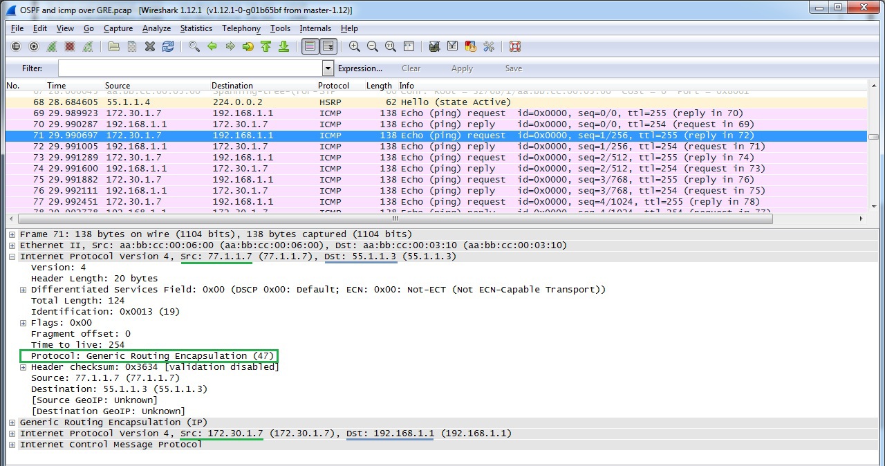
Gre , (OSPF, EIGRP) IPv6 . IP ( 47) GRE . GRE , Cisco, RFC 2784.
GRE point-to-point . () .
| LNS# interface Tunnel1 ip address 10.3.7.3 255.255.255.0 tunnel source Ethernet0/1 tunnel destination 77.1.1.7 | LAC# interface Tunnel1 ip address 10.3.7.7 255.255.255.0 tunnel source Ethernet0/0 tunnel destination 55.1.1.3 |
| GRE, OSFP | |
| LNS# router ospf 1 network 10.3.9.0 0.0.0.255 area 0 network 10.3.7.0 0.0.0.255 area 0 network 192.168.1.0 0.0.0.255 area 0 | LAC# router ospf 1 network 10.3.7.0 0.0.0.255 area 0 network 172.30.1.0 0.0.0.255 area 0 |
OSPF
| LAC #sh ip ospf neighbor Neighbor ID Pri State Dead Time Address Interface 3.3.3.3 0 FULL/ - 00:00:30 10.3.7.3 Tunnel1 , OSPF, . LAC #sh ip route ospf 10.3.9.0/8 is variably subnetted, 3 subnets, 2 masks O 10.3.9.0/24 [110/2000] via 10.3.7.3, 00:19:02, Tunnel1 < — R3 <-> R9 99.0.0.0/32 is subnetted, 1 subnets O 99.99.99.99 [110/2001] via 10.3.7.3, 00:19:02, Tunnel1 < — loopback R9 O 192.168.1.0/24 [110/1010] via 10.3.7.3, 00:19:02, Tunnel1 < — HQ LAC#ping 192.168.1.1 source 172.30.1.7 Type escape sequence to abort. Sending 5, 100-byte ICMP Echos to 192.168.1.1, timeout is 2 seconds: Packet sent with a source address of 172.30.1.7 !!!!! Success rate is 100 percent (5/5), round-trip min/avg/max = 1/1/1 ms |
:
GRE over IPSec
| LNS# crypto isakmp policy 10 encr 3des authentication pre-share group 2 ! crypto isakmp key ipseckey123 address 77.1.1.7 ! crypto ipsec transform-set ESP-AES256-SHA1 esp-aes 256 esp-sha-hmac mode transport ! crypto map GREoverIPSec 5 ipsec-isakmp set peer 77.1.1.7 set transform-set ESP-AES256-SHA1 match address GRE ! ! GRE 47, 47 ip access-list extended GRE permit gre any any ! interface Ethernet0/1 ip address 55.1.1.3 255.255.255.0 crypto map GREoverIPSec | LAC# crypto isakmp policy 10 encr 3des authentication pre-share group 2 ! crypto isakmp key ipseckey123 address 55.1.1.3 ! crypto ipsec transform-set ESP-AES256-SHA1 esp-aes 256 esp-sha-hmac mode transport ! crypto map GREoverIPSec 5 ipsec-isakmp set peer 55.1.1.3 set transform-set ESP-AES256-SHA1 match address GRE ! ! ip access-list extended GRE permit gre any any ! interface Ethernet0/0 ip address 77.1.1.7 255.255.255.0 crypto map GREoverIPSec ! ! |
GRE over IPSec
| LAC #ping 192.168.1.1 source 172.30.1.7 Type escape sequence to abort. Sending 5, 100-byte ICMP Echos to 192.168.1.1, timeout is 2 seconds: Packet sent with a source address of 172.30.1.7 !!!!! Success rate is 100 percent (5/5), round-trip min/avg/max = 4/5/6 ms IPSec LAC #sh crypto isakmp sa IPv4 Crypto ISAKMP SA dst src state conn-id status 55.1.1.3 77.1.1.7 QM_IDLE 1001 ACTIVE (SA) LAC #sh crypto ipsec sa interface: Ethernet0/0 Crypto map tag: GREoverIPSec , local addr 77.1.1.7 protected vrf: (none) local ident (addr/mask/prot/port): (0.0.0.0/0.0.0.0/47/0) remote ident (addr/mask/prot/port): (0.0.0.0/0.0.0.0/47/0) current_peer 55.1.1.3 port 500 PERMIT, flags={origin_is_acl,} # pkts encaps : 109, #pkts encrypt: 28559, #pkts digest: 28559 # pkts decaps : 184, #pkts decrypt: 28784, #pkts verify: 28784 #pkts compressed: 0, #pkts decompressed: 0 #pkts not compressed: 0, #pkts compr. failed: 0 #pkts not decompressed: 0, #pkts decompress failed: 0 #send errors 0, #recv errors 0 local crypto endpt.: 77.1.1.7, remote crypto endpt.: 55.1.1.3 path mtu 1500, ip mtu 1500, ip mtu idb Ethernet0/0 current outbound spi: 0xBCF71DA2(3170311586) PFS (Y/N): N, DH group: none |
:
OSPF over GRE over IPSec
OSPF ( network type broadcast)
| LAC #sh ip ospf neighbor Neighbor ID Pri State Dead Time Address Interface 3.3.3.3 0 FULL/ - 00:00:31 10.3.7.3 Tunnel1 |
DMVPN
DMVPN implements multipoint GRE architecture, allowing you to use, firstly, one address space for all vpn remote offices, secondly, to pass through the tunnel a large list of third-party protocols, as well as multicast, and thirdly, to establish dynamically tunnels between regional remote sites in case of traffic between them. However, there is one thing, this technology is only realizable on a mono-vendor network on Cisco.
Configure the HQ router as DMVPN HUB, Spoke 1 as DMVPN Client
| HUB # interface Tunnel1 description DMVPN_HUB /// mGRE setup ip address 10.5.5.1 255.255.255.0 tunnel source FastEthernet0 / 0 tunnel mode gre multipoint tunnel key 111001 no ip redirects ip mtu 1416 /// NHRP setup ip nhrp map multicast dynamic ip nhrp network-id 101 ip nhrp server-only ip tcp adjust-mss 1376 end | Spoke # interface Tunnel1 ip address 10.5.5.3 255.255.255.0 no ip redirects ip mtu 1416 ip nhrp map multicast dynamic ip nhrp map multicast 192.168.1.1 (address) ip nhrp map 10.5.5.1 192.168.1.1 ip nhrp network-id 101 ip nhrp nhs 10.5.5.1 (tunnel address) ip tcp adjust-mss 1380 keepalive 10 3 tunnel source FastEthernet0 / 0 tunnel mode gre multipoint tunnel key 111001 end |
DMVPN operation check
Check whether the tunnel is established to DMVPN HUBa.
Please note that NBMA address is the real address of HUBa.
| Spoke #sh dmvpn Legend: Attrb -> S - Static, D - Dynamic, I - Incomplete N - NATed, L - Local, X - No Socket # Ent -> Number of NHRP entries with same NBMA peer NHS Status: E -> Expecting Replies, R -> Responding, W -> Waiting UpDn Time -> Up or Down Time for a Tunnel ================================================= ======================== Interface: Tunnel1, IPv4 NHRP Details Type: Spoke, NHRP Peers: 1, # Ent Peer NBMA Addr Peer Tunnel Add State UpDn Tm Attrb - - - - - ----- 1 192.168.1.1 10.5.5.254 UP 00:02:59 S Two connected remote offices are visible on HUBe: Hub #sh dmvpn Legend: Attrb -> S - Static, D - Dynamic, I - Incomplete N - NATed, L - Local, X - No Socket # Ent -> Number of NHRP entries with same NBMA peer NHS Status: E -> Expecting Replies, R -> Responding, W -> Waiting UpDn Time -> Up or Down Time for a Tunnel ================================================= ======================== Interface: Tunnel1, IPv4 NHRP Details Type: Hub, NHRP Peers: 2, # Ent Peer NBMA Addr Peer Tunnel Add State UpDn Tm Attrb - - - - - ----- 1 172.16.1.2 10.5.5.1 UP 00:04:08 D 1 172.16.2.3 10.5.5.2 UP 00:02:57 D A bunch of tunnel address and real (physical) Hub # sh ip nhrp brief Target Via NBMA Mode Intfc Claimed 10.5.5.1/32 10.5.5.1 172.16.1.2 dynamic Tu1 <> 10.5.5.2/32 10.5.5.2 172.16.2.3 dynamic Tu1 <> |
Creating a dynamic GRE tunnel from a remote office Spoke1 to Spoke2
At the start of the boot, the Spoke 1 had only 1 tunnel to HUB. When generating traffic (ping) to Spoke2, a tunnel to Spoke2 was immediately created.
| Router # ping 10.5.5.2 Type escape sequence to abort. Sending 5, 100-byte ICMP Echos to 10.5.5.2, timeout is 2 seconds: !!!!! Success rate is 100 percent (5/5), round-trip min / avg / max = 1/4/5 ms We look at the established tunnels at the moment: Router # sh dmvpn Legend: Attrb -> S - Static, D - Dynamic, I - Incomplete N - NATed, L - Local, X - No Socket # Ent -> Number of NHRP entries with same NBMA peer NHS Status: E -> Expecting Replies, R -> Responding, W -> Waiting UpDn Time -> Up or Down Time for a Tunnel ================================================= ======================== Interface: Tunnel1, IPv4 NHRP Details Type: Spoke, NHRP Peers: 2, # Ent Peer NBMA Addr Peer Tunnel Add State UpDn Tm Attrb - - - - - ----- 1 172.16.2.3 10.5.5.2 UP 00:04:04 D 1 192.168.1.1 10.5.5.254 UP 00:09:31 S |
At the moment, the network diagram (Fig. 13) will look like this:
Dynamic Routing Protocols via DMVPN
OSPF Setup
Making the settings via DMVPN and including the common network for VPN 10.5.5.0 in the OSPF process - we will see how OSPF on the HUB will establish contiguous relationships first with Spoke1 until it receives a hello packet from Spoke2, after that the relationships collapse with Neighbor Down: Adjacency error forced to reset, since the default interface Tunnel is set as the point-to-point interface. For OSPF to work correctly, you need to set the network type as broadcast. If you set the broadcast only on HUBe, then the neighborhood will be established, but there will be no routes through OSPF on Spok-a, so you need to set the broadcast on both the HUB and Spoke-ah.
Below are the tables of OSPF behavior depending on the selected network type value.
| Hub | Spoke 1 | Spoke 2 |
| BROADCAST | BROADCAST | BROADCAST |
| Hub # sh ip opf neighbor Neighbor I Pri State Dead Time Address Interface 1.1.1.1 0 FULL / DROTHER 00:00:34 10.5.5.1 Tunnel1 2.2.2.2 0 FULL / DROTHER 00:00:31 10.5.5.2 Tunnel1 Spoke_1 # sh ip ospf neighbor Neighbor ID Pri State Dead Time Address Interface 10.0.0.1 1 FULL / DR 00:00:36 10.5.5.254 Tunnel1 Spoke_1 # sh ip ospf neighbor Neighbor ID Pri State Dead Time Address Interface 10.0.0.1 1 FULL / DR 00:00:36 10.5.5.254 Tunnel1 Known routes to Spoke 1 via OSPF Spoke_1 # sh ip route Gateway of last resort is 172.16.1.5 to network 0.0.0.0 S * 0.0.0.0/0 [1/0] via 172.16.1.5 1.0.0.0/32 is subnetted, 1 subnets C 1.1.1.1 is directly connected, Loopback1 2.0.0.0/32 is subnetted, 1 subnets O 2.2.2.2 [110/1001] via 10.5.5.3, 00:00:07, Tunnel1 <- Spoke2 internal network 10.0.0.0/8 is variably subnetted, 3 subnets, 2 masks O 10.0.0.0/24 [110/1001] via 10.5.5.254, 00:05:19, Tunnel1 <- internal network of the Central Office C 10.5.5.0/24 is directly connected, Tunnel1 L 10.5.5.1/32 is directly connected, Tunnel1 172.16.0.0/16 is variably subnetted, 2 subnets, 2 masks C 172.16.1.0/24 is directly connected, GigabitEthernet0 / 0 L 172.16.1.2/32 is directly connected, GigabitEthernet0 / 0 Connectivity between Spoke 1 and Spoke 2 is done directly: Spoke_1 # traceroute 2.2.2.2 source 1.1.1.1 Type escape sequence to abort. Tracing the route to 2.2.2.2 VRF info: (vrf in name / id, vrf out name / id) 1 10.5.5.3 216 msec 256 msec 216 msec | ||
DMVPN with EIGRP
| HUB (R1) | Spoke (R3) | Spoke (R4) |
| By default, routes on Spoke are only HUB (due to the split-horizon, Spoke 2 routes are not visible) | ||
| HUB # sh ip route eigrp 1.0.0.0/8 is variably subnetted, 2 subnets, 2 masks D 1.0.0.0/8 is a summary, 00:04:18, Null0 D 3.0.0.0/8 [90/409600] via 10.5.5.3, 00:04:24, Tunnel1 D 4.0.0.0/8 [90/409600] via 10.5.5.4, 00:03:51, Tunnel1 10.0.0.0/8 is variably subnetted, 3 subnets, 2 masks D 10.0.0.0/8 is a summary, 00:04:18, Null0 There is no route to 4.4.4.4 Spoke_1 # sh ip route eigrp D 1.0.0.0/8 [90/324096] via 10.5.5.1, 00:04:04, Tunnel4 3.0.0.0/8 is variably subnetted, 2 subnets, 2 masks D 3.0.0.0/8 is a summary, 00:04:11, Null0 10.0.0.0/8 is variably subnetted, 3 subnets, 2 masks D 10.0.0.0/8 is a summary, 00:04:11, Null0 | ||
Turn off on the HUBe split-horizon
| HUB (R1) | Spoke (R3) | Spoke (R4) |
| HUB (conf) # router eigrp 1 no ip split-horizon eigrp 1 | No additional settings | No additional settings |
| HUB # sh ip route eigrp 1.0.0.0/8 is variably subnetted, 2 subnets, 2 masks D 1.0.0.0/8 is a summary, 00:04:18, Null0 D 3.0.0.0/8 [90/409600] via 10.5.5.3, 00:04:24, Tunnel101 D 4.0.0.0/8 [90/409600] via 10.5.5.4, 00:03:51, Tunnel101 10.0.0.0/8 is variably subnetted, 3 subnets, 2 masks D 10.0.0.0/8 is a summary, 00:04:18, Null0 The route to Spoke1 appeared, but leads through HUB Spoke_1 # sh ip route eigrp D 1.0.0.0/8 [90/324096] via 10.5.5.1, 00:05:45, Tunnel4 3.0.0.0/8 is variably subnetted, 2 subnets, 2 masks D 3.0.0.0/8 is a summary, 00:00:26, Null0 D 4.0.0.0 / 8 [90/435200] via 10.5.5.1 , 00:00:26, Tunnel4 10.0.0.0/8 is variably subnetted, 3 subnets, 2 masks D 10.0.0.0/8 is a summary, 00:05:51, Null0 R3 # traceroute 4.4.4.4 source 3.3.3.3 Type escape sequence to abort. Tracing the route to 4.4.4.4 1 10.5.5.1 88 msec 92 msec 76 msec 2 10.5.5.4 128 msec * 140 msec | ||
Let's get rid of HUB as an intermediate device in the connectivity of Spoke1 <-> Spoke2
| HUB (R1) | Spoke (R3) | Spoke (R4) |
| HUB (conf) # router eigrp 1 no ip split-horizon eigrp 1 no ip next-hop-self eigrp 1 | No additional settings | No additional settings |
| Now the route to the network Spoke_2 leads directly: R3 # sh ip route eigrp 1 D 1.0.0.0/8 [90/324096] via 10.5.5.1, 00:00:06, Tunnel4 3.0.0.0/8 is variably subnetted, 2 subnets, 2 masks D 3.0.0.0/8 is a summary, 00:00:06, Null0 D 4.0.0.0 / 8 [90/435200] via 10.5.5.4 , 00:00:04, Tunnel4 10.0.0.0/8 is variably subnetted, 3 subnets, 2 masks D 10.0.0.0/8 is a summary, 00:19:55, Null0 R3 # traceroute 4.4.4.4 source 3.3.3.3 Type escape sequence to abort. Tracing the route to 4.4.4.4 1 10.5.5.4 84 msec * 72 msec | ||
PPTP
PPTP became a joint development of Microsoft, 3Com, Ascend Communication consortia. Well scalable protocol. It can be used to connect offices as a point-to-point, but most of all is suitable for organizing a remote connection on a client-server architecture. It is enough to configure the central PPTP VPN HUB, and remote users connect through the PPTP client, which is implemented in all Windows OS, including MacOS and Linux distributions.
There are cryptographic problems in the MSCHAPv2 authentication protocol [https://technet.microsoft.com/ru-ru/library/security/2743314.aspx], so in most cases even L2TP over IPSec is recommended instead of PPTP on Windows .
Only one Microsoft Point-to-Point Encryption protocol (128-bit key) is used as encryption means, and MSCHAPv2, PEAP (recommended) is used as authentication.
PPTP in its work establishes 2 sessions: a PPP session using the GRE protocol and a TCP connection on port 1723 for serving the PPTP session.
Establishing a TCP session before establishing a PPP connection
PPP package format (fig.15)
| PPTP_HUB # Username cisco2 password cisco2 ! interface Loopback1 ip address 192.168.2.2 255.255.255.0 ! vpdn enable ! vpdn-group 1 ! Default PPTP VPDN group accept-dialin protocol pptp virtual-template 1 ! interface Virtual-Template1 ip unnumbered Loopback1 ip mtu 1400 ip tcp adjust-mss 1360 peer default ip address pool PPTP-Pool ppp encrypt mppe auto ppp authentication ms-chap-v2 chap callin ! ip local pool PPTP-Pool 192.168.2.5 192.168.2.50 ! |
Checking the established PPTP connections.
User cisco2 is logged in and session is established.
| PPTP_HUB #sho vpdn session % No active L2TP tunnels PPTP Session Information Total tunnels 1 sessions 1 LocID RemID TunID Intf Username State Last Chg Uniq ID 55592 0 17168 vi3 cisco2 estabd 00:04:13 6 |
The user is given an ip address from the DHCP Pool and created virtual-access
| PPTP_HUB # sh ip int br Interface IP Address OK? Method Status Protocol Ethernet0 / 0 unassigned YES NVRAM administratively down down GigabitEthernet0 / 0 192.168.1.3 YES NVRAM up up GigabitEthernet1 / 0 77.1.1.3 YES NVRAM up up Loopback0 3.3.3.3 YES NVRAM up up Loopback1 192.168.2.2 YES NVRAM up up Virtual-Access1 unassigned YES unset down down Virtual-Access2 unassigned YES unset up up Virtual-Access3 192.168.2.5 YES unset up up Virtual-Template1 192.168.2.5 YES unset down down |
If there is a task for a specific PPTP client to issue an IP address belonging only to it, then you can resort to creating a TXT file listing all PPTP clients.
Setup on the router:
| ip dhcp pool STATIC import all origin file flash: /static2.txt default-router 192.168.2.2 dns-server 8.8.8.8 8.8.4.4 domain-name lab.local lease 3 ! interface Virtual-Template1 ip unnumbered Loopback1 ip mtu 1400 ip tcp adjust-mss 1360 peer default ip address pool STATIC (PPTP-Pool is no longer needed) ppp encrypt mppe auto ppp authentication ms-chap-v2 chap callin |
The TXT file itself is static2.txt.
| * time * Mar 01 2002 12:23 AM * version * 2 ! IP address Type VRF hardware address lease expiration 192.168.2.77 / 25 1000c.2984.4f84 Infinite 192.168.2.17 / 25 1000c.294646.1575 Infinite 192.168.2.18 / 25 10000.0000.1111 Infinite |
L2TP
L2TP is an IETF standard that incorporates the best of Cisco's L2F protocol and Microsoft's PPTP. It does not offer data protection tools, so it is often used with IPSec.
L2TP is one of the few representatives of VPN protocols (also available for implementation in a corporate network), which pseudowire technology can offer - forwarding native vlan via L3 network. The pseudowire technology only supports L2TP version 3. In addition, L2TPv3 supports the following L2 protocols, the data (payloads) of which can be transparently transmitted through the pseudo-tunnel L2TPv3:
- Ethernet
- Ethernet VLAN (802.1q)
- HDLC
- PPP
- MPLS
The main difference between L2TPv3 and L2TPv2 is that L2TPv3 can tunnel different types of traffic (see above), while v2 only PPP.
L2TPv3 uses two types of messages:
- Signal (Control Connection)
- For data (Session data)
L2TPv3 signaling messages and data messages can be transferred via IP (protocol ID 115), i.e. L2TPv3 uses less overhead
| IP_add_s_global IP_add_d_global Type 115 |
| L2TP_header |
| L2_sublayer |
| Data |
L2TPv2 encapsulates data in IP / UDP (UDP port 1701).
| IP_add_s_global IP_add_d_global |
| UDP_s_port UDP_d_port (1701) |
| L2TP_header |
| PPP_header |
| IP_add_s_local IP_add_d_local |
| Data |
L2TPv3 Pseudowire
The L2TP architecture, as well as the PPTP architecture, uses the following concepts:
| LAC | L2TP access concentrator | LAC accepts requests from the client and negotiates L2TP tunnel and session parameters with LNS and transmits the LNS request |
| Lns | L2TP network server | LNS negotiates L2TP tunnel and session parameters with LAC |
| LCCE | L2TP Control Connection Endpoint | This is the LAC that participates in the signal connection. |
The protocol operation model for L2TPv3 LNS is LNS, and for L2TPv2 LAC is LNS (for details, see below).
Let's create a pseudowire between R5 in the Central Office and in R9 in the regional office, thereby expanding the network 192.168.1.x / 24 to the regional office.
| R5 # pseudowire-class L2TP_Class encapsulation l2tpv3 protocol none (i.e. dynamic session setup is not used) ip pmtu ip local interface GigabitEthernet1 / 0 ! interface GigabitEthernet0 / 0 no ip address xconnect 44.1.1.9 1 encapsulation l2tpv3 manual pw-class L2TP_Class l2tp id 1 2 l2tp cookie local 4 55111 l2tp cookie remote 44119 | R9 # pseudowire-class L2TP_Class encapsulation l2tpv3 protocol none (i.e. dynamic session setup is not used) ip pmtu ip local interface GigabitEthernet0 / 0 ! interface GigabitEthernet1 / 0 no ip address xconnect 55.1.1.1 1 encapsulation l2tpv3 manual pw-class L2TP_Class l2tp id 2 1 l2tp cookie local 4 44119 l2tp cookie remote 4 55111 |
Session establishment check:
| R5_VPN_HUB_Pr # sh l2tp session L2TP Session Information Total tunnels 0 sessions 1 LocID RemID TunID Username, Intf / State Last Chg Uniq ID Vcid Circuit 1 2 n / a 1, Gi0 / 0 est 00:00:03 1 R5_VPN_HUB_Pr # sh l2tp session all L2TP Session Information Total tunnels 0 sessions 1 Session id 1 is up, logical session id 33356, tunnel id n / a Remote session id is 2, remote tunnel id n / a Locally initiated session Unique ID is 4 Session Layer 2 circuit, type is Ethernet, name is GigabitEthernet0 / 0 Session vcid is 1 Circuit state is UP Local circuit state is UP Remote circuit state is UP Call serial number is 0 Remote tunnel name is Internet address is 44.1.1.9 Local tunnel name is Internet address is 55.1.1.5 IP protocol 115 Session is manually signaled Session state is established, time since change 02:29:58 1130 Packets sent, 1982 received 151213 Bytes sent, 197759 received Last clearing of counters never |
R7 is now available without routing protocols:
| R10 # ping 192.168.1.7 repeat 10 Type escape sequence to abort. Sending 10, 100-byte ICMP Echos to 192.168.1.7, timeout is 2 seconds: !!!!!!!!!! Success rate is 100 percent (10/10), round-trip min / avg / max = 128/142/180 ms |
OSPF over L2TP
Neighborhood established by default, including the network 192.168.1.0 on R7 and R10
| R7_DATA_Center_Servers # sh ip ospf neighbor Neighbor ID Pri State Dead Time Address Interface 192.168.1.10 1 FULL / DR 00:00:37 192.168.1.10 GigabitEthernet0 / 0 R10 # sh ip ospf neighbor Neighbor ID Pri State Dead Time Address Interface 7.7.7.7 1 FULL / BDR 00:00:35 192.168.1.7 GigabitEthernet0 / 0 |
Disadvantages:
If L2TP is created on a router as in our example, then the following L2 PDUs will not go through pseudowire connections: CDP, STP, VTP, LLDP. To tunnel such protocols, you must create an L2TPv3 tunnel on the L3 switch.
Big minus - we have to remove the ip address on the interface of the router, which serves as the default route for all other stations. As a result, our PCs remain without communication with other networks.
L2 VPN works in two modes:
- mandatory tunnel mode
- voluntary (optional) tunnel mode.
Mandatory tunnel mode refers to provider-provisioning and L2F, PPTP, L2TP protocols operate in this mode. In mandatory tunnel mode via L2TP, remote users connect to the LAC via a normal PPP connection, the LAC terminates them and tunnels the PPP session to the LNS. Moreover, the remote user does not even suspect about L2TP.
In a voluntary / client initiated tunnel, the remote host acts as a LAC, that is, it negotiates and establishes an L2TP session directly with the LNS.
In our example, Cisco R9 (44.1.1.9) will act as a LAC and establish an L2TP connection with Cisco R5 in the data center (55.1.1.1), which will act as an LNS.
| * Oct 20 19: 52: 55.861: L2X tnl 08287: ________: Create logical tunnel * Oct 20 19: 52: 55.865: L2TP tnl 08287: ________: Create tunnel * Oct 20 19: 52: 55.869: L2TP tnl 08287: ________: version set to V2 ( L2TPv2 protocol ) * Oct 20 19: 52: 55.873: L2TP tnl 08287: ________: remote ip set to 44.1.1.9 * Oct 20 19: 52: 55.873: L2TP tnl 08287: ________: local ip set to 55.1.1.1 * Oct 20 19: 52: 55.877: L2TP tnl 08287: 00003073: FSM-CC ev Rx-SCCRQ ( Start - Control - Connection - Request ) LNS checks the validity of the sender and the availability of its own resources, and the list of supported pseudowire types ( Ethernet , Frame Relay ) is also consistent at this stage * Oct 20 19: 52: 55.877: L2TP tnl 08287: 00003073: FSM-CC Idle-> Proc-SCCRQ * Oct 20 19: 52: 55.877: L2TP tnl 08287: 00003073: FSM-CC do Rx-SCCRQ * Oct 20 19: 52: 55.881: L2X _____: ________: Tunnel author started for LAC * Oct 20 19: 52: 55.901: L2X _____: ________: Tunnel author found * Oct 20 19: 52: 55.905: L2TP tnl 08287: 00003073: Author reply, data source: "VPDN-L2TP" * Oct 20 19: 52: 55.909: L2X _____: ________: class [AAA author, group "VPDN-L2TP"] * Oct 20 19: 52: 55.913: L2X _____: ________: created * Oct 20 19: 52: 55.917: L2TP tnl 08287: 00003073: FSM-CC ev SCCRQ-OK * Oct 20 19: 52: 55.917: L2TP tnl 08287: 00003073: FSM-CC Proc-SCCRQ-> Wt-SCCCN Start-Control-Connection-Connected (SCCCN) wait for the state Connected * Oct 20 19: 52: 55.917: L2TP tnl 08287: 00003073: FSM-CC do Tx-SCCRP Start-Control-Connection-Reply (SCCRP) sent a reply message * Oct 20 19: 52: 55.917: L2X _____: ________: l2x_open_socket: is called * Oct 20 19: 52: 55.921: L2TP tnl 08287: 00003073: Open sock 55.1.1.1: 1701 -> 44.1.1.9: 1701 Uses UDP with port 1701 for service messages * Oct 20 19: 52: 55.925: L2TP tnl 08287: 00003073: FSM-CC ev Sock-Ready * Oct 20 19: 52: 55.929: L2TP tnl 08287: 00003073: FSM-CC in Wt-SCCCN * Oct 20 19: 52: 55.929: L2TP tnl 08287: 00003073: FSM-CC do Ignore-Sock-Up * Oct 20 19: 52: 55.941: L2X _____: ________: Disabled security for VPDN * Oct 20 19: 52: 56.053: L2TP tnl 08287: 00003073: FSM-CC ev Rx-SCCCN * Oct 20 19: 52: 56.053: L2TP tnl 08287: 00003073: FSM-CC Wt-SCCCN-> Proc-SCCCN * Oct 20 19: 52: 56.053: L2TP tnl 08287: 00003073: FSM-CC do Rx-SCCCN * Oct 20 19: 52: 56.053: L2TP tnl 08287: 00003073: Got a response in SCCCN from LAC * Oct 20 19: 52: 56.057: L2TP tnl 08287: 00003073: Tunnel Authentication success * Oct 20 19: 52: 56.061: L2TP tnl 08287: 00003073: FSM-CC ev SCCCN-OK * Oct 20 19: 52: 56.065: L2TP tnl 08287: 00003073: FSM-CC Proc-SCCCN-> established * Oct 20 19: 52: 56.069: L2TP tnl 08287: 00003073: FSM-CC do Established * Oct 20 19: 52: 56.073: L2TP tnl 08287: 00003073: Control channel up * Oct 20 19: 52: 56.077: L2TP tnl 08287: 00003073: 55.1.1.1 <-> 44.1.1.9 |
The service channel is established, the channel for data ( PPP frames) is now established .
It is worth noting that a set of client sessions can take place on one established tunnel.
To set up a session for LAC data, it sends an ICRQ (Call-Request), if there are enough resources on the LNS, then the LNS responds with an ICRP (Call-Reply) message. To complete the session establishment - LAC sends ICCN Incoming-Call-Connected.
| * Oct 20 19: 52: 56.117: L2X _____: _____: ________: Create logical session * Oct 20 19: 52: 56.121: L2TP _____: _____: ________: Create session * Oct 20 19: 52: 56.121: L2TP _____: _____: ________: Using ICRQ FSM Incoming-Call-Request (ICRQ) The required pseudowire type required for the L2 level is transmitted here * Oct 20 19: 52: 56.125: L2TP _____: _____: ________: remote ip set to 44.1.1.9 * Oct 20 19: 52: 56.125: L2TP _____: _____: ________: local ip set to 55.1.1.1 * Oct 20 19: 52: 56.129: L2TP tnl 08287: 00003073: FSM-CC ev Session-Conn * Oct 20 19: 52: 56.129: L2TP tnl 08287: 00003073: FSM-CC in established * Oct 20 19: 52: 56.129: L2TP tnl 08287: 00003073: FSM-CC do Session-Conn-Est * Oct 20 19: 52: 56.129: L2TP tnl 08287: 00003073: Session count now 1 * Oct 20 19: 52: 56.129: L2TP _____: 08287: 0000754C: Session attached * Oct 20 19: 52: 56.129: L2TP _____: 08287: 0000754C: FSM-Sn ev Rx-ICRQ * Oct 20 19: 52: 56.129: L2TP _____: 08287: 0000754C: FSM-Sn Idle-> Proc-ICRQ * Oct 20 19: 52: 56.129: L2TP _____: 08287: 0000754C: FSM-Sn do Rx-ICRQ * Oct 20 19: 52: 56.129: L2TP _____: 08287: 0000754C: Chose application VPDN * Oct 20 19: 52: 56.133: L2TP _____: 08287: 0000754C: App type set to VPDN * Oct 20 19: 52: 56.133: L2TP tnl 08287: 00003073: VPDN Session count now 1 * Oct 20 19: 52: 56.189: L2TP 00005: 08287: 0000754C: FSM-Sn ev ICRQ-OK * Oct 20 19: 52: 56.193: L2TP 00005: 08287: 0000754C: FSM-Sn Proc-ICRQ-> Wt-Tx-ICRP * Oct 20 19: 52: 56.193: L2TP 00005: 08287: 0000754C: FSM-Sn do Tx-ICRP-Local-Check * Oct 20 19: 52: 56.193: L2TP 00005: 08287: 0000754C: FSM-Sn ev Local-Cont * Oct 20 19: 52: 56.193: L2TP 00005: 08287: 0000754C: FSM-Sn Wt-Tx-ICRP-> Wt-Rx-ICCN * Oct 20 19: 52: 56.193: L2TP 00005: 08287: 0000754C: FSM-Sn do Tx-ICRP Incoming-Call-Reply (ICRP) * Oct 20 19: 52: 56.197: L2TP 00005: 08287: 0000754C: Open sock 55.1.1.1:1701->44.1.1.9.90101 * Oct 20 19: 52: 56.197: L2TP 00005: 08287: 0000754C: FSM-Sn in Wt-Rx-ICCN ( awaiting ICCN) * Oct 20 19: 52: 56.397: L2TP 00005: 08287: 0000754C: FSM-Sn ev Rx-ICCN ( received ICCN ) * Oct 20 19: 52: 56.401: L2TP 00005: 08287: 0000754C: FSM-Sn Wt-Rx-ICCN-> Proc-ICCN * Oct 20 19: 52: 56.405: L2TP 00005: 08287: 0000754C: FSM-Sn do Rx-ICCN * Oct 20 19: 52: 56.437: L2TP 00005: 08287: 0000754C: FSM-Sn ev ICCN-OK * Oct 20 19: 52: 56.441: L2TP 00005: 08287: 0000754C: FSM-Sn Proc-ICCN-> established * Oct 20 19: 52: 56.445: L2TP 00005: 08287: 0000754C: FSM-Sn do Established * Oct 20 19: 52: 56.449: L2TP 00005: 08287: 0000754C: Session up (The session is established for the data) * Oct 20 19: 52: 58.197: L2TP 00005: 08287: 0000754C: FSM-Sn in established * Oct 20 19: 52: 58.241:% LINEPROTO-5-UPDOWN: Line protocol on Interface Virtual-Access3, changed state to up * Oct 20 19: 52: 58.273:% LINK-3-UPDOWN: Interface Virtual-Access3, changed state to up |
In our example, one tunnel was formed between the LAS and the LNS and one user session.
| ISP_NAT # sh l2tun tunnel L2TP Tunnel Information Total tunnels 1 sessions 1 LocTunID RemTunID Remote Name State Remote Address Sessn L2TP Class / Count VPDN Group 30933 12403 LNS est 55.1.1.1 1 1 ISP_NAT # sh l2tp session L2TP Session Information Total tunnels 1 sessions 1 LocID RemID TunID Username, Intf / State Last Chg Uniq ID Vcid Circuit 32700 30028 30933 LNS, Vi1 est 00:51:35 0 |
The L2TP configuration in the voluntary tunnel mode is very similar in configuration with the mandatory tunnel mode. The difference in setting up a VPDN group is as follows:
- The terminate-from command is not needed
- L2TP tunnel authentication disabled by no l2tp tunnel authentication command
Configure L2TPv2
interface virtual-ppp, interface Dialer. «AS IS».
| LNS# aaa new-model aaa authorization network default local ! vpdn enable vpdn-group VPDN-L2TP accept-dialin protocol l2tp virtual-template 2 lcp renegotiation on-mismatch terminate-from hostname LAC l2tp tunnel password 0 cisco123 ip pmtu ! interface Virtual-Template2 ip unnumbered GigabitEthernet0/0 autodetect encapsulation ppp peer default ip address pool L2TP-pool ppp authentication ms-chap-v2 | LAC# vpdn enable ! vpdn-group 1 request-dialin protocol l2tp pool-member 1 initiate-to ip 55.1.1.1 source-ip 44.1.1.9 local name LAC ( terminate-from LNS) l2tp tunnel password 0 cisco123 ! interface Dialer1 ip address negotiated encapsulation ppp dialer pool 1 dialer idle-timeout 0 dialer string 123 dialer vpdn dialer-group 1 ppp authentication chap callin ppp chap hostname LNC ppp chap password 0 cisco123 ! ip route 192.168.1.0 255.255.255.0 Dialer1 |
L2TPv2 interface virtual-ppp
| LNS# aaa new-model ! aaa authorization network default local ! username LAC password 0 cisco123 ! vpdn enable vpdn-group VPDN-L2TP accept-dialin protocol l2tp virtual-template 2 terminate-from hostname LAC l2tp tunnel password 0 cisco123 ! interface Loopback0 ip address 3.3.3.3 255.255.255.255 ! interface Virtual-Template2 ip unnumbered Loopback0 autodetect encapsulation ppp no peer default ip address ppp authentication ms-chap-v2 ! ip route 172.30.1.0 255.255.255.0 7.7.7.7 ! R7 (PS 7.7.7.7 LNS#show ip route 7.0.0.0/32 is subnetted, 1 subnets C 7.7.7.7 is directly connected, Virtual-Access3 ) | LAC# username LNS password 0 cisco123 ! l2tp-class client.init.class authentication password cisco123 ! pseudowire-class pwclass1 encapsulation l2tpv2 protocol l2tpv2 client.init.class ip local interface Ethernet0/0 ! interface Loopback0 ip address 7.7.7.7 255.255.255.255 ! interface Virtual-PPP1 ip unnumbered loopback0 ppp authentication ms-chap-v2 no cdp enable pseudowire 55.1.1.3 1 pw-class pwclass1 ! ip route 192.168.1.0 255.255.255.0 Virtual-PPP1 ! (PS 3.3.3.3 3.0.0.0/32 is subnetted, 1 subnets C 3.3.3.3 is directly connected, Virtual-PPP1 ) |
(LAC) L2TP HUBe (LNS)
| LNS#show vpdn L2TP Tunnel and Session Information Total tunnels 1 sessions 1 LocTunID RemTunID Remote Name State Remote Address Sessn L2TP Class/ Count VPDN Group 60224 63290 LAC est 77.1.1.7 1 VPDN-L2TP LocID RemID TunID Username, Intf/ State Last Chg Uniq ID Vcid, Circuit 46580 40688 60224 LAC, Vi3 est 00:14:12 102 LAC#sho vpdn L2TP Tunnel and Session Information Total tunnels 1 sessions 1 LocTunID RemTunID Remote Name State Remote Address Sessn L2TP Class/ Count VPDN Group 63290 60224 LNS est 55.1.1.3 1 client.init.cla LocID RemID TunID Username, Intf/ State Last Chg Uniq ID Vcid, Circuit 40688 46580 63290 1, Vp1 est 00:20:54 8 |
| LNS#sh caller user LAC User: LAC, line Vi3, service PPPoVPDN Connected for 00:03:34, Idle for 00:00:04 Timeouts: Limit Remaining Timer Type — — - PPP: LCP Open, MS CHAP V2 (<-->), IPCP IP: Local 3.3.3.3, remote 7.7.7.7 Counts: 101 packets input , 2932 bytes, 0 no buffer 0 input errors, 0 CRC, 0 frame, 0 overrun 78 packets output, 3770 bytes, 0 underruns 0 output errors, 0 collisions, 0 interface resets < ping- > LNS#sh caller user LAC User: LAC, line Vi3, service PPPoVPDN Connected for 00:03:40, Idle for 00:00:02 Timeouts: Limit Remaining Timer Type — — - PPP: LCP Open, MS CHAP V2 (<-->), IPCP IP: Local 3.3.3.3, remote 7.7.7.7 Counts: 201 packets input , 13332 bytes, 0 no buffer 0 input errors, 0 CRC, 0 frame, 0 overrun 179 packets output, 15650 bytes, 0 underruns 0 output errors, 0 collisions, 0 interface resets | ( LNS) R7 LAC# ping 192.168.1.1 source 172.30.1.7 repeat 100 Type escape sequence to abort. Sending 100, 100-byte ICMP Echos to 192.168.1.1, timeout is 2 seconds: Packet sent with a source address of 172.30.1.7 !!!!!!!!!!!!!!!!!!!!!!!!!!!!!!!!!!!!!!!!!!!!!!!!!!!!!!!!!!!!!!!!!!!!!! !!!!!!!!!!!!!!!!!!!!!!!!!!!!!! Success rate is 100 percent (100/100), round-trip min/avg/max = 1/4/6 ms |
L2TPv2
Overhead UDP (8) + L2TPv2 (8) + PPP (4 ) +IPv4 (20 ) = 40
OSPF L2TPv2
| OSPF broadcast LNS# router ospf 1 network 3.3.3.3 0.0.0.0 area 0 network 192.168.1.0 0.0.0.255 area 0 default-information originate always | 3.3.3.3 ospf area 0 LAC# interface Loopback1 ip address 77.77.77.77 255.255.255.255 ! router ospf 1 network 3.3.3.3 0.0.0.0 area 0 network 77.77.77.77 0.0.0.0 area 0 |
LSA OSPF L2TPv2
, , overhead.
Overhead UDP (8) + L2TPv2 (8) + PPP (4 ) +IPv4 (20 ) = 40
| LNS #sh ip ospf neighbor Neighbor ID Pri State Dead Time Address Interface 7.7.7.7 0 FULL/ - 00:00:30 7.7.7.7 Virtual-Access3 LAC #sh ip ospf neighbor Neighbor ID Pri State Dead Time Address Interface 3.3.3.3 0 FULL/ - 00:00:35 3.3.3.3 Virtual-PPP1 |
L2TPv3
L2TPv3 , VPN HUB- .
| LNS# username LAC password 0 cisco123 ! pseudowire-class client.init.pw encapsulation l2tpv3 protocol l2tpv3 client.inint.class ip local interface Ethernet0/1 ! interface Virtual-PPP1 ip unnumbered Loopback0 ppp authentication ms-chap-v2 pseudowire 77.1.1.7 1 pw-class client.init.pw ! interface Loopback0 ip address 3.3.3.3 255.255.255.255 ! interface Virtual-PPP1 ip unnumbered Loopback0 ppp authentication ms-chap-v2 pseudowire 77.1.1.7 1 pw-class client.init.pw ! ip route 172.30.1.0 255.255.255.0 Virtual-PPP1 | LAC# username LNS password 0 cisco123 ! pseudowire-class pwclass2 encapsulation l2tpv3 protocol l2tpv3 client.init.class ip local interface Ethernet0/0 ! interface Virtual-PPP1 ip address negotiated ppp authentication ms-chap-v2 no cdp enable pseudowire 55.1.1.3 1 pw-class pwclass2 ! ip route 192.168.1.0 255.255.255.0 Virtual-PPP1 |
L2TPv3 LNS
| LNS#show vpdn L2TP Tunnel and Session Information Total tunnels 1 sessions 1 LocTunID RemTunID Remote Name State Remote Address Sessn L2TP Class/ Count VPDN Group 4168123058 3050381103 LAC est 77.1.1.7 1 client.inint.cl LocID RemID TunID Username, Intf/ State Last Chg Uniq ID Vcid, Circuit 2122433254 2810410257 4168123058 1, Vp1 est 00:16:22 53 est ablished, ID |
L2TPv3 LAC
| LAC #show vpdn L2TP Tunnel and Session Information Total tunnels 1 sessions 1 LocTunID RemTunID Remote Name State Remote Address Sessn L2TP Class/ Count VPDN Group 3050381103 4168123058 LNS est 55.1.1.3 1 client.init.cla LocID RemID TunID Username, Intf/ State Last Chg Uniq ID Vcid, Circuit 2810410257 2122433254 3050381103 1, Vp1 est 00:15:57 5 |
L2TPv3
Overhead L2TPv3 (4) + HDLC (4) = 8
(LAC) L2TP HUBe (LNS)
| L2 TPv3 LNS# show caller user LAC User: LAC, line Vp1, service PPP Connected for 00:01:52, Idle for 00:01:52 Timeouts: Limit Remaining Timer Type - - - PPP: LCP Open, MS CHAP V2 (<-->), IPCP IP: Local 3.3.3.3, remote 7.7.7.7 Counts: 1241 packets input, 74748 bytes, 0 no buffer 0 input errors, 0 CRC, 0 frame, 0 overrun 1078 packets output, 78056 bytes, 0 underruns 0 output errors, 0 collisions, 0 interface resets < ping- > LNS#show caller user LAC User: LAC, line Vp1, service PPP Connected for 00:02:02, Idle for 00:02:02 Timeouts: Limit Remaining Timer Type - - - PPP: LCP Open, MS CHAP V2 (<-->), IPCP IP: Local 3.3.3.3, remote 7.7.7.7 Counts: 1343 packets input, 84976 bytes, 0 no buffer 0 input errors, 0 CRC, 0 frame, 0 overrun 1180 packets output, 88552 bytes, 0 underruns 0 output errors, 0 collisions, 0 interface resets | 100 LAC#ping 192.168.1.1 source 172.30.1.7 repeat 100 Type escape sequence to abort. Sending 100, 100-byte ICMP Echos to 192.168.1.1, timeout is 2 seconds: Packet sent with a source address of 172.30.1.7 !!!!!!!!!!!!!!!!!!!!!!!!!!!!!!!!!!!!!!!!!!!!!!!!!!!!!!!!!!!!!!!!!!!!!!!!!!!!!!!!!!!!!!!!!!!!!!!!!!!! Success rate is 100 percent (100/100), round-trip min/avg/max = 2/4/29 ms |
L2TPv2 over IPSec
L2TP , IPSec. L2TP , , PPP . L2TPv2, IP/UDP , ACL UDP 1701. IPSec , , ( ), IP ( ).
:
| LNS# crypto isakmp policy 10 encr 3des authentication pre-share group 2 ! crypto isakmp key ipseckey123 address 77.1.1.7 ! crypto ipsec transform-set ESP-AES256-SHA1 esp-aes 256 esp-sha-hmac mode transport ! crypto map L2TP_VPN 10 ipsec-isakmp set peer 77.1.1.7 set transform-set ESP-AES256-SHA1 match address L2TP_TRAFFIC ! ! L2TPv2, ! UDP ! 1701 ip access-list extended L2TP_TRAFFIC permit udp host 55.1.1.3 eq 1701 host 77.1.1.7 eq 1701 ! interface Ethernet0/1 ip address 55.1.1.3 255.255.255.0 crypto map L2TP_VPN | LAC# crypto isakmp policy 10 encr 3des authentication pre-share group 2 ! crypto isakmp key ipseckey123 address 55.1.1.3 ! crypto ipsec transform-set ESP-AES256-SHA1 esp-aes 256 esp-sha-hmac mode transport ! crypto map L2TP_VPN 10 ipsec-isakmp set peer 55.1.1.3 set transform-set ESP-AES256-SHA1 match address L2TP_TRAFFIC ! ! ip access-list extended L2TP_TRAFFIC permit udp host 77.1.1.7 eq 1701 host 55.1.1.3 eq 1701 ! interface Ethernet0/0 ip address 77.1.1.7 255.255.255.0 crypto map L2TP_VPN ! ! |
(LAC) L2TP HUBe (LNS)
| L2 TPv3 LNS# sh caller user LAC User: LAC, line Vi3, service PPPoVPDN Connected for 00:04:10, Idle for 00:00:05 Timeouts: Limit Remaining Timer Type - - - PPP: LCP Open, MS CHAP V2 -->), IPCP IP: Local 3.3.3.3, remote 7.7.7.7 Counts: 247 packets input, 16456 bytes, 0 no buffer 0 input errors, 0 CRC, 0 frame, 0 overrun 129 packets output, 3846 bytes, 0 underruns 0 output errors, 0 collisions, 0 interface resets < ping- > LNS#sh caller user LAC User: LAC, line Vi3, service PPPoVPDN Connected for 00:04:45, Idle for 00:00:02 Timeouts: Limit Remaining Timer Type - - - PPP: LCP Open, MS CHAP V2 (ß>), IPCP IP: Local 3.3.3.3, remote 7.7.7.7 Counts: 327 packets input , 23288 bytes, 0 no buffer 0 input errors, 0 CRC, 0 frame, 0 overrun 188 packets output, 4226 bytes, 0 underruns 0 output errors, 0 collisions, 0 interface resets | 100 LAC#ping 192.168.1.1 repeat 100 source 172.30.1.7 Type escape sequence to abort. Sending 100, 100-byte ICMP Echos to 192.168.1.1, timeout is 2 seconds: !.!!!!!!!.!!!!!.!!!!!.!!!.!!!!!..!.!!!!!!!!!!!!.!!!!!..!!!!. |
L2TPv2 over IPSec
IP | ESP header | UDP | L2TP | PPP | ESP trailer | Auth trailer
Overhead ESP_header (8) + UDP (8) + L2TPv2 (8) + PPP (4 ) + ESP_trailer (min 2) + SHA_auth (160 = 20 ) = 50 a
OSPF over L2TPv2 over IPSec
OSPF , hello - 10 . OSPF .
| LNS#sh ip ospf neighbor Neighbor ID Pri State Dead Time Address Interface 7.7.7.7 0 FULL/ - 00:00:35 7.7.7.7 Virtual-Access3 192.168.1.1 1 FULL/DR 00:00:33 192.168.1.1 Ethernet0/0 LNS#sh ip route C 7.7.7.7 is directly connected, Virtual-Access3 O 77.77.77.77/32 [110/2] via 7.7.7.7, 21:54:59, Virtual-Access3 172.30.0.0/24 is subnetted, 1 subnets S 172.30.1.0 [1/0] via 7.7.7.7 192.168.1.0/24 is variably subnetted, 2 subnets, 2 masks |
Scaling. L2TPv2
LNS, .. L2TPv2 HUB – PPP CHAP . , :
| *Nov 9 10:31:35.178: VPDN uid:123 disconnect (AAA) IETF: 17/user-error Ascend: 26/PPP CHAP Fail *Nov 9 10:31:35.178: VPDN uid:123 vpdn shutdown session, result=2, error=6, vendor_err=0, syslog_error_code=8, syslog_key_type=1 |
LAC
| LNS# username LAC_9 password 0 cisco123 | LAC_9# username LNS password 0 cisco123 ! l2tp-class client.init.class authentication password cisco123 ! pseudowire-class pwclass1 encapsulation l2tpv2 protocol l2tpv2 client.init.class ip local interface Ethernet0/0 ! interface Loopback0 ip address 9.9.9.9 255.255.255.255 ! interface Virtual-PPP1 ip address loopback0 ppp authentication ms-chap-v2 no cdp enable pseudowire 55.1.1.3 1 pw-class pwclass1 ! ip route 192.168.1.0 255.255.255.0 Virtual-PPP1 |
LNS 2
| LNS#sh vpdn tunnel L2TP Tunnel Information Total tunnels 2 sessions 2 LocTunID RemTunID Remote Name State Remote Address Sessn L2TP Class/ Count VPDN Group 35949 21672 LAC est 77.1.1.7 1 VPDN-L2TP 49973 18492 LAC_9 est 44.1.1.9 1 VPDN-L2TP |
OSPF L2TPv2
L2TPv2 – . OSPF loopback-:
| LNS# interface Loopback0 ip address 3.3.3.3 255.255.255.255 router ospf 1 network 3.3.3.3 0.0.0.0 area 0 | LAC# interface Loopback0 ip address 7.7.7.7 255.255.255.255 ! interface Loopback1 ip address 77.77.77.77 255.255.255.255 ! router ospf 1 router-id 7.7.7.7 network 7.7.7.7 0.0.0.0 area 0 network 77.77.77.77 0.0.0.0 area 0 | LAC_9# interface Loopback0 ip address 9.9.9.9 255.255.255.255 ! interface Loopback1 ip address 99.99.99.99 255.255.255.255 ! router ospf 1 router-id 9.9.9.9 network 9.9.9.9 0.0.0.0 area 0 network 99.99.99.99 0.0.0.0 area 0 |
OSPF
| LNS#sh ip ospf neighbor Neighbor ID Pri State Dead Time Address Interface 9.9.9.9 0 FULL/ - 00:00:39 9.9.9.9 Virtual-Access3 7.7.7.7 0 FULL/ - 00:00:39 7.7.7.7 Virtual-Access4 192.168.1.1 1 FULL/DR 00:00:39 192.168.1.1 Ethernet0/0 R3 – L2TPv2 HUB LAC_9# sh ip route ospf ( R7) 7.0.0.0/32 is subnetted, 1 subnets O 7.7.7.7 [110/3] via 3.3.3.3, 00:02:14, Virtual-PPP1 77.0.0.0/32 is subnetted, 1 subnets O 77.77.77.77 [110/3] via 3.3.3.3, 00:02:14, Virtual-PPP1 : LAC_9#traceroute 77.77.77.77 source 99.99.99.99 Type escape sequence to abort. Tracing the route to 77.77.77.77 VRF info: (vrf in name/id, vrf out name/id) 1 3.3.3.3 5 msec 2 msec 4 msec 2 7.7.7.7 5 msec 4 msec * |
OSPF, ( L2TP HUBe) – ip ppp .
IP , 1 , 192.168. 25.0 /24 interface virtual-ppp VPN HUBa, - 192.168. 25.16 /29 , VPN HUB vitual-ppp :
HUB (conf)#ip route 192.168.25.16 255.255.255.248 16.16.16.16 (<- 16.16.16.16 virtual-ppp , VPN HUBa :
| C 16.16.16.16 is directly connected, Virtual-Access4) |
, , . , , , , . , «» , , ! .
PS
: , VPN-, — , VPN- .
.
Source: https://habr.com/ru/post/246281/
All Articles