Monitoring Methods in DWDM Systems (Part 1)
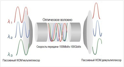
The basic principle of WDM technology (Wavelength-division multiplexing, frequency division of channels) is the ability to transmit multiple signals at different carrier wavelengths in one optical fiber. In Russian telecom, transmission systems created using WDM technology are called “compression systems”.
Currently there are three types of WDM systems:
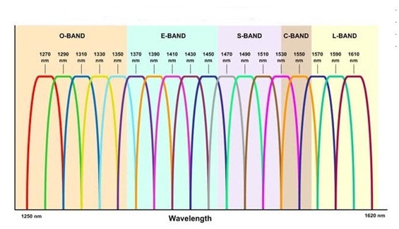
1. CWDM (Coarse Wavelength-division multiplexing - coarse frequency division of channels) —systems with optical carrier spacing of 20 nm (2500 GHz). The working range is 1261–1611 nm, in which up to 18 simplex channels can be realized. ITU Standard G.694.2.
2. DWDM (Dense Wavelength-division multiplexing - dense frequency division of channels) - systems with a spacing of optical carriers at 0.8 nm (100 GHz). There are two working ranges - 1525-1565 nm and 1570-1610 nm, in which up to 44 simplex channels can be realized. ITU Standard G.694.1.
3. HDWDM (High Dense Wavelength-division multiplexing - high-density frequency division channels) - systems with optical carrier spacing of 0.4 nm (50 GHz) or less. Up to 80 simplex channels are possible.
')
In this article (review), attention is paid to the problem of monitoring in DWDM compression systems, for more information about the various types of WDM systems, please refer to the link .
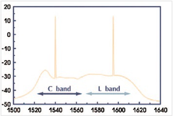
DWDM spectral multiplexing systems can use one of two carrier wavelength ranges: the C-band — 1525–1565 nm (the conventional band or C-band can also occur) and the L-band – 1570–1610 nm (long wavelength band or L-band).
The division into two ranges is based on the use of different optical amplifiers with different operating amplification ranges. The gain bandwidth for a conventional amplifier configuration is approximately 30 nm, 1530–1560 nm, which is the C-band. For amplification in the long-wavelength range (L-band), the configuration of the erbium amplifier is changed by lengthening the erbium fiber, which leads to a shift of the gain range in the wavelengths of 1560-1600 nm.
At the moment, in the Russian telecom, C-band DWDM equipment has received great recognition. This is due to the abundance of various equipment that supports this range. It should be noted that equipment manufacturers act as venerable domestic companies and leading global brands, as well as numerous faceless Asian manufacturers.
The main issue in any part of the compression system (regardless of the type) is the power level in the optical channel. First you need to figure out what the DWDM sealing system usually consists of.
Components of a DWDM system:
1) Transponder
2) Multiplexer / demultiplexer
3) Optical amplifier
4) Chromatic dispersion compensator

The transponder performs 3R regeneration (“reshaping,“ re-amplifying ”,“ retiming ”—recovering the shape, power, and timing of the signal) of the incoming client optical signal. The transponder can also convert client traffic from one transmission protocol (often Ethernet) to another, more noise-proof (for example, OTN using FEC) and transmit the signal to the line port.

In simpler systems, the OEO converter can act as a transponder, which performs 2R regeneration (“reshaping”, “re-amplifying”) and transmits the client signal to the line port without changing the transmission protocol.
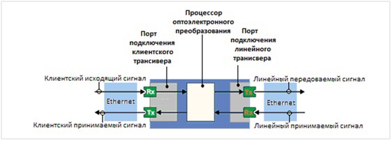
The client port is often implemented as a slot for optical transceivers into which a module is inserted to communicate with the client equipment. The linear port in the transponder can be made in the form of a slot for an optical transceiver or in the form of a simple optical adapter. The performance of the line port depends on the design and purpose of the system as a whole. In the OEO converter, the line port is always configured as a slot for an optical transceiver.
In many systems, the intermediate link is a transponder, which is excluded in order to reduce the cost of the system or because of functional redundancy in a particular task.
Optical multiplexers are designed for combining (mixing) separate WDM channels into a group signal for simultaneous transmission over a single optical fiber. Optical demultiplexers are designed to separate the received group signal at the receiving side. In modern compression systems, the multiplexing and demultiplexing functions are performed by one device - the multiplexer / demultiplexer (MUX / DEMUX).
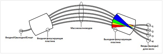
The multiplexer / demultiplexer can be divided into a multiplexing unit and a demultiplexing unit.
An optical amplifier based on an impurity optical fiber doped with erbium (Erbium Doped Fiber Amplifier-EDFA), increases the power of the grouped (without prior demultiplexing) optical signal entering it without an optoelectronic conversion. The EDFA amplifier consists of two active elements: active fiber doped with Er3 + and suitable pumping.
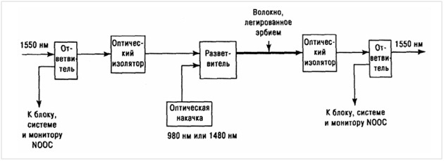
Depending on the type, EDFA can provide output power from +16 to +26 dBm.
There are several types of amplifiers, the use of which is determined by a specific task:
• Input optical power amplifiers (boosters) - installed at the beginning of the track
• Optical preamps - installed at the end of the track in front of the optical receivers
• Linear optical amplifiers — are installed at intermediate amplification nodes to maintain the required optical power.
Optical amplifiers are widely used on long data lines with DWDM spectral multiplexing systems.
The Dispersion Compensation Module is designed to correct the shape of optical signals transmitted in an optical fiber, which, in turn, are distorted under the influence of chromatic dispersion.
Chromatic dispersion is a physical phenomenon in an optical fiber, which consists in the fact that light signals with different wavelengths travel the same distance for a different period of time and, as a result, the transmitted optical pulse broadens. Thus, chromatic dispersion is one of the main factors limiting the length of the relay portion of the route. Standard fiber has a chromatic dispersion value of about 17 ps / nm.
To increase the length of the relay section, compensators of chromatic dispersion are installed on the transmission line. The installation of compensators often requires a transmission line with a speed of 10 Gbit / s and more.
There are two main types of DCM:
1. Chromatic dispersion fiber - DCF (Dispersion Compensation Fiber). The main component of these passive devices is a fiber with a negative chromatic dispersion value in the 1525-1565 nm wavelength range.
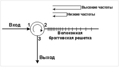
2. Chromatic dispersion compensator based on Bragg grating - DCM FBG (Dispersion Compensation Module Fiber Bragg Grating). Passive optical device consisting of chirped fiber and optical circulator. Chirped fiber due to the structure creates a conditionally negative chromatic dispersion of incoming signals in the wavelength range of 1525-1600 nm. The optical circulator in the device acts as a filtering device, which directs the signals to the appropriate terminals.
Thus, the standard scheme consists of only two types of active components — a transponder and an amplifier, with which you can monitor the current power level of transmitted signals. In transponders, the function of monitoring the state of the linear ports is implemented either on the basis of the built-in DDMI function in optical transceivers, or with the organization of its own monitoring. Using this function allows the operator to obtain current information about the status of a particular communication channel.
Due to the fact that optical amplifiers are amplifiers with feedback, they always have the function of monitoring the input group signal (total optical power of all incoming signals) and the outgoing group signal. But this monitoring is inconvenient in the case of monitoring specific communication channels and can be used as an evaluation (the presence or absence of light). Thus, the only instrument for monitoring the optical power in the data transmission channel is a transponder.
And since compaction systems consist not only of active, but also of passive elements, the organization of complete monitoring in compaction systems is a very trivial and demanded task.
Options for organizing monitoring in WDM compression systems will be discussed in the next article.

Source: https://habr.com/ru/post/246095/
All Articles