We simulate the prestress of the concrete shell of the nuclear power plant
 Dear habrovchane!
Three months have passed since the start of the Masters of Simulation project , and we already have results that we would like to share with you.
We received quite a lot of applications and were very pleased that this initiative of ours found a lively response in the minds and hearts of engineers and designers, young graduate students and already experienced specialists. The tasks that the project participants sent us in their questionnaires turned out to be interesting and, at times, very extraordinary. There was here the calculation of processes in the destruction of structures, and the calculation of composite materials, and highly linear processes, and much more.
')
The greatest progress in the decision was achieved in the following three forms:
1. Objective: to simulate the prestressing of the “piece” of the concrete shell with friction and slip losses. Author: Markevich Maxim Aleksandrovich
2. Task: Modeling the stiffness of linear guides and rolling bearings. To analyze the stiffness of individual nodes (mechatronic modules) of machine tools. Author: Yusupov Nail Hamitovich
3. Challenge: It is necessary to obtain temperature fields and stresses in a multilayer structure when exposed to a temperature source and under the action of a power load. Author: Dolgopolova Natalya Vladimirovna
Below in this publication we give a detailed description of the solution of the problem of Maxim Aleksandrovich Markevich mentioned above.
So…
Imperfect Techniques - The Path to Disasters
Designing nuclear power plants (NPPs) is an extremely important task, because cases of negligence are too expensive for all of humanity. Traditionally, nuclear power plant elements such as the inner containment of the reactor compartment are calculated using the theory of plates and shells. This is a technique that allows you to get an accurate analytical calculation. But the word “exact”, in fact, would be nice to put in quotes, because this calculation was performed after a large number of simplifications and assumptions. So, very often, the anisotropy of the behavior of concrete due to reinforcement is not taken into account, the fact of pretensioning and physical nonlinearity in behavior is simplified. Not to mention the fact that many features of the containment geometry are simply ignored: for example, the influence of local features on the uneven distribution of stresses over the shell and its thickness. All this is usually corrected by a set of coefficients, with the help of which excess strength from operational loads is achieved. And in most cases it is enough. However, such a technique may not be enough, and this can lead to a catastrophe. And here comes to the fore the need to significantly increase the detail of calculations, take into account previously discarded factors, use more accurate methods to accomplish the task, with which you can make less simplifications and idealizations in the design. As a consequence, a more adequate method is required to account for such effects.
Naturally, in the framework of the project “Masters of Simulation” no one takes responsibility for the preparation of a new method for calculating and designing the protective shell of nuclear power plants, which will immediately go into operation. But in one of the applications received, we found questions about the fundamental possibility of taking into account some of the effects of such design using the Autodesk Simulation line. And it was precisely to these questions that we tried to find more accurate answers. Not just to say "yes, of course," but also to tell "how exactly."
Initial data
The original setting was described as follows:
To simulate the prestresses of the “piece” of the shell with friction and sliding losses - Maxim Aleksandrovich Markevich, engineer of the RUP Belnipienergoprom company.

Fig. 1. Image provided by the author of the task for its explanation
I would like to thank Maxim Alexandrovich for the prompt answers to the questions and the interest shown in solving his own problem. This allowed a much deeper work on the task.
We now turn to a more detailed description of the problem. And we begin with a description of the structure under study.
The inner containment of the reactor compartment of an NPP is made of pre-stressed monolithic reinforced concrete in the form of a cylinder, covered with a hemisphere-shaped dome (Fig. 2).

Fig. 2. Protective sheath (1 - outer reinforced concrete sheath; 2 - inner metal sheath)
The containment prestressing system (SPZO) consists of reinforcing beams, supporting anchor blocks, ducting formers, equipment for assembling reinforcing beams, their tension, and a diagnostic system for reinforcing beams (Fig. 3, Fig. 4).

Fig. 3. Section of the containment along the axis

Fig. 4. The cross section of the protective sheath perpendicular to the axis
For prestressing, strands of cable reinforcement in polyethylene sheath are used. Each reinforcing cable has a polyethylene sheath and is located in a channel former filled with a special injection solution (Fig. 5). Thus, there is no connection between the reinforcing beam and the concrete of the containment shell. If necessary, this allows for the possibility of tightening or replacing the rope. Channel formers are metal pipes and flexible metal pipes with an outer diameter of not more than 219 mm and a thickness of about 3-5 mm.

Fig. 5. Cross section of channel former and reinforcing rope
Description of reinforcement: Prestressed reinforcement (Fig. 5) - bundles consisting of 55 ropes with a diameter of 15.7, 17.4-19.4 mm, HDPE type with lubrication. Durability class - 1860 MPa. Similar fittings are manufactured by Trefileurope (France.
Actually the decision
Now you can smoothly go to the solution of the task. Let's start with some comments and conclusions that can be made on the basis of the available information:
1. In the concrete of the main part of the containment sheaths are built in. Their main goal: to separate the ropes from the concrete and to give the opportunity to stretch these ropes, creating a prestressed state, and replace the ropes if necessary.
2. The channel former does not have any particular rigidity and, therefore, in the first approximation, it can most likely be ignored. But due to the difference in stiffness of the ducting materials and concrete, it can work as a pressure redistributor from the ropes.
3. The above (in paragraph 2) fact needs to be verified.
4. The channel former has an extremely small thickness compared with the basic dimensions of the structure, and its simulation in a volumetric formulation can lead to a very high dimensional problem. Therefore, the channel former will be executed in Autodesk Inventor as a surface, and during CE analysis it will be modeled by plate elements in those tasks in which it will be taken into account (Fig. 6).

Fig. 6. Channel formers built surfaces
5. It is also necessary separately to consider a small part of the structure near the channel former in order to see the local behavior of the structure. On the basis of this, it will be possible to draw conclusions about the need for modeling channel-makers (Fig. 7).

Fig. 7. Detailed volumetric model of the local shell segment and the channel former
6. It also makes sense to solve the problem of contact interaction between a rope and a channel former within a given local piece (Fig. 7). This will allow the best way to choose the type of contact and resolve the issue of the possibility of replacing the pre-stressed rope with its power counterpart.
7. Thus, the basic geometric model for the basic calculation began to look as follows (Fig. 8). This is a solid-body bulk geometric model of the shell (or rather, parts of it) with voids for the ropes. The ropes are also made in the form of bulk elements. Channel formers, as mentioned earlier, are made in the form of surfaces.

Fig. 8. The original version of the part of the structure under study in Inventor.
Analysis
To solve this problem from the arsenal of Autodesk calculation programs, you can use: Autodesk Simulation Mechanical (ASM), Autodesk Nastran In-CAD, Autodesk Sim 360. Part of the problem can be solved by using the Inventor Professional functionality, or rather, its Inventor Simulation module. In the case of a positive solution of the first part of the problem, development is expected towards solving the coupled thermo-strength problem, therefore, ASM was chosen as the basic tool for solving the problem. A detailed step-by-step description of the solution to the problem will be published a little later, but now we proceed to the formulation of the problem.
8. For the first calculations, the grid was selected by default, and the global concentration to 30%. A general view of the QE grid is shown in Fig. 9. In the task tree, you can see three-dimensional parts and a number of parts divided into lamellar-shell elements (selected in the tree).

Fig. 9. QE-grid of the source object under study.
9. After conducting various types of contacts for the current task, the most suitable in ASM were identified: “Sliding / No Separation” and “Surface”. The contact type “Bonded”, which is offered by ASM by default, in this case leads to a fundamentally wrong behavior of the structure, since the ropes do not have the ability to freely slide along the channel-former (as it should be), but are rigidly glued over the entire surface to the channel-former and concrete.
10. To speed up the counting in the first approximation, the contact type will be “Sliding / No Separation”, hereinafter “Surface”.
11. In the cylindrical part of the shell, the vertical ropes practically do not interact with the channel, and in fact simply create a compressive force at the ends of the shell along the border of the holes of the channel former. At the same time, the presence of vertical ropes in the model make a very small correction, and at the first steps they can be excluded from the calculation model.
12. The cement-reinforcing ropes themselves need a separate description and calculation of their mechanical properties.
Because of their structure and production method, steel ropes (Fig. 10) work very well in tension, but they practically do not work in compression. Due to the fact that in the current case, the ropes are bound by the injecting cement mortar, the resulting reinforcement-cement composite gets some resistance to compressive loads.

Fig. 10. Examples of ropes and cables
This feature could introduce non-linearity in the behavior of the object under study, if not for the fact that the ropes are poured with cement mortar in an already pre-stretched form. As a result, even with some compressive load, the ropes are still stretched, and continue to work only in tension. Consequently, the non-linear properties of the reinforced cement rope can be neglected. However, in view of the fact that the rope works as a whole, it is, in fact, a composite, whose characteristics depend on the materials used, but differ significantly from them. Ideally, it is necessary to conduct a comprehensive study of the part of the rope for its work along all directions and to calculate the anisotropic characteristics of the final composite material. However, in the first step, the anisotropy of the properties can be neglected, because:
1) the properties of the structure will strongly depend on the location of the ropes, which may vary in some way,
2) in classical calculations, the geometry of the ropes and their properties are generally not taken into account, and, therefore, this will already be a step forward. In this case, it is proposed to calculate the mechanical characteristics according to the volume fraction.
Nevertheless, in the future we can recommend a more detailed consideration of the behavior of the ropes (Fig. 11).

Figure 11. Stress distribution with axial compression of reinforcement-cement rope
13. Cement-reinforcing ropes work under conditions of prestressing by stretching and are considered isotropic according to the characteristics of the material. Their properties are calculated by the classical formulas for composite materials:
elastic modulus (E), Poisson’s ratio (v) depending on volume:

14. To simulate symmetric boundary conditions, Frictionless type fastening (Fig. 12) on three sides (two sides and bottom) will be used. For sidewalls, thus, the behavior is simulated, similar to the presence of the plane of symmetry. For the lower side, additional research is needed regarding the correctness of the type of fastening, in view of the fact that the lower part should be able to perform plane-parallel movement (in its entirety).

Fig. 12. Boundary conditions (fixation)
The preload level will be set by force (Force) normal to the ends of the rope.

Fig. 13. Force conditions
Thus, there are a number of simplifications and a number of controversial points that it makes sense to check additionally during the test calculations. Some of them were tested on the basis of the original geometry built on the basis transmitted by the customer. For some tasks, separate models were built, focused on testing a particular effect.
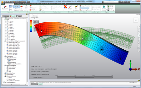
The results of test calculations (various stresses and displacements) with the included scale (10% of the dimensions of the geometry) are shown below in Figures 14-20.

Fig. 14. Total movements

Fig. 15. District movements

Fig. 16. Radial displacement

Fig. 17. Equivalent Mises Stress

Fig. 18. Radial stresses

Fig. 19. District voltages

Fig. 20. Shift
Analysis of VAT shows that the primary statement needs to be clarified. This is best demonstrated on radial movements with the model deformation option enabled on a scale of 40% of the structure dimensions (Fig. 21):

Fig. 21. Deformation of the object is shown in scale.
With the correct formulation, the model should be almost uniformly compressed, and not twisted around the center. In view of the fact that the fasteners are absolutely identical on both sides, this may indicate the occurrence of significant unevenness from the load that was applied on one of the sides. Also near the boundary surfaces, one can observe the distortion of the VAT pattern, due to the influence of edge effects. Thus, based on the preliminary calculations, we can draw the following conclusions:
Conclusions on preliminary calculations
- To adequately solve the original problem, one should take a larger area of the shell (approximately 3-4 times) (Fig. 22). In this case, edge effects will not appear in the central area.

Fig. 22. Proposed for the study version of the design.
- To determine the detailed VAT and the level of stress concentration, a local section of concrete with a rope will be simulated. In this case, the channel former will be modeled as a solid geometry.
- To compensate for power skew and more symmetrical deformation of the shell, it makes sense to apply forces in a staggered manner on both sides of the shell (Fig. 23).

Fig. 23. The proposed method of loading
For the shell, you can use the default setting, for the ropes and the central part, it makes sense to set the mesh size (40% of the nominal) - this will make the mesh balanced in terms of accuracy / speed.
The results obtained allowed us to proceed to the second stage, during which the formulation will be refined and the solution of the problem obtained will be obtained. If the second stage is successfully completed, it is possible to consider a more complex task in the field of multiphysics, namely, solving the problem of the thermally stressed state of the containment shell, taking into account the preload and working pressure.
In one of the following posts we will talk about the work on the second project - modeling the stiffness of linear guides and rolling bearings.
Successful work and we remind you that the acceptance of applications for participation in the “Masters of Simulation” program continues.
Read more about the project and conditions of participation .
Fill out the application form for participation .
Source: https://habr.com/ru/post/245861/
All Articles