The future of parametric CAD
Today it is impossible to imagine the design of buildings, structures or parts of mechanisms without the use of CAD-systems. The 90s brought a revolution in the CAD industry, when PTC demonstrated a parametric approach that greatly simplified the work of an engineer, saving him from part of the routine procedures that arose with minimal modification of the drawing. The parametric element-oriented (feature-based) approach has become the de facto standard, but many issues remained unresolved, primarily because of the complexity of the calculations that arise when parametrizing a drawing. Almost 20 years have passed, but CAD technology seems to have not advanced a single step. Now we have powerful computers that are many times superior to any systems available in the early 90s, heterogeneous computing is being used everywhere, the latest video cards contain thousands of streaming cores. Stagnant in CAD time has come to change.
In this article, I would like to introduce you to what parametric CAD is and what problems it is experiencing in the present, to talk about our research, and about solutions that can drastically change the entire industry in the coming years.
')
To begin with, I would like to briefly describe what CAD is in general and what parametric CAD is in particular. If you are familiar with these concepts, feel free to skip the next two paragraphs and go directly to the point.
Regardless of what you are going to do - develop a complex mechanism, build a house, or simply rearrange the furniture in the room - you will need a drawing. With the help of the drawing, you can visualize the project to find its strengths, weaknesses, contradictions. After all, it is not always possible to think over everything in detail “in the head”. In addition, the drawing allows you to convey your vision of any design to other people, and exchanging ideas to gradually improve it.
The process of creating a drawing is called drawing. This is a whole science that has been improved for many centuries along with engineering progress, and by the beginning of the 20th century it had acquired a large number of clear methodologies and useful tools, making drawing creation more formalized, separating it from the visual arts and bringing it closer to pure engineering.
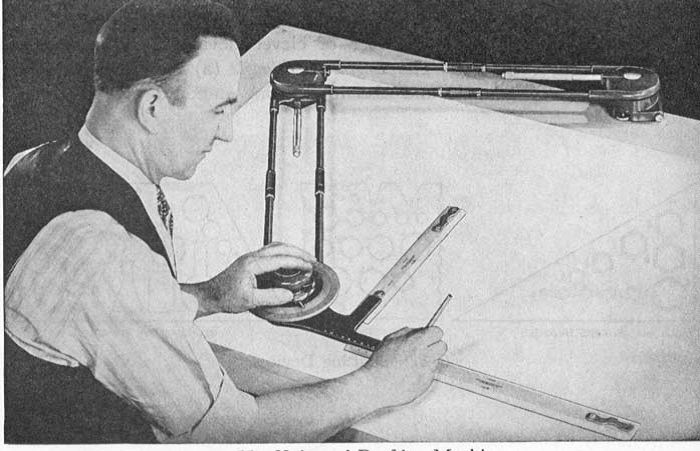
Traditionally, the process of drawing begins with the fact that you take a sheet of paper and fix it on a flat surface or on a special drawing table. Then you start to draw something with a pencil with a set of special devices (T-square, rulers, patterns, etc.).
Personally, I find it difficult to draw a straight line even along a ruler, so at school I had certain problems with drawing - any mistake and you need to redraw everything.
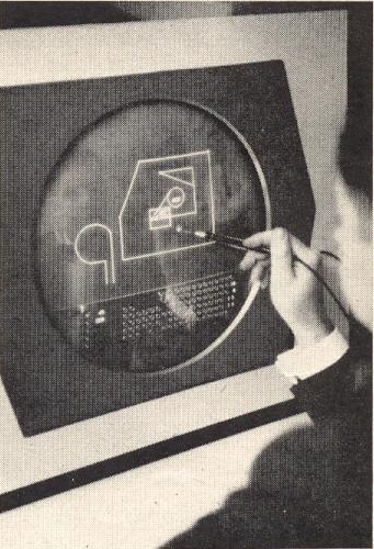
Back in the 60s, attempts began to be made to use computers for technical design, but only in the late 70s and early 80s, user-friendly programs appeared along with the avalanche-like spread of personal computers, which allowed to transfer the drawing process from drawing panels to monitors.
Such systems (first a software and hardware bundle, then just a program) began to be denoted by computer acronym CAD from English Computer-Aided Design , which can be roughly translated as computer-aided design. In Russia, for such systems, the abbreviation of CAD (Computer Aided Design) was established, which, however, implies not only CAD , but also CAE ( Computer-Aided Engineering ) and CAM ( Computer-Aided Manufacturing) . computer help).
Originally, 2D CAD systems were based on a coordinate approach. This means that when the operator created lines in a 2D drawing, the program recorded the coordinates of the end points of each line. Problems of this approach occur when you need to change the drawing (for example, increase the length of any line) - even a small change usually requires manually updating the numerous lines affected by the change in the drawing.
The parametric approach allows the engineer to think in terms of size (linear and angular) and geometric constraints instead of being tied to coordinates. With this approach, you draw geometric primitives (points, lines, circles, arcs, etc.) and set dimensions and geometric constraints for them (for example, parallelism, perpendicularity, equality of lengths, etc.). The software independently builds a system of equations in which the coordinates of the points will be unknown, and the dimensions and geometric constraints will be the equations that determine the solution. In the parametric approach, if you make any changes, you do not need to “correct” anything in the drawing yourself, the system will automatically recalculate the coordinates of all points based on the specified dimensions and geometric constraints, and then redraw the model.
The idea of the parametric approach is very simple, clear and attractive. Imagine that you spent several months drawing a large building (and even in several sections with plans for each floor), brought a drawing to the customer, and he asked to extend the window openings by several centimeters. Without parameterization, this would mean a serious rework, which can take a lot of time. If, on the other hand, it is correct to set dimensions and geometric constraints, then the problem is solved automatically by changing only one parameter.
Unfortunately, not everything is so simple. In the case of real drawings - the resulting system of equations can be very large and complex. It can contain many thousands of equations and millions of variables. No modern parametric CAD system is able to handle parametrized models of such complexity. Very often, their behavior is unstable even for models containing a small number of geometric primitives. Moreover, even if they are able to handle a relatively large model, it may take a long time to get a result, which makes working with such a model uncomfortable.
Modern parametric CAD systems are based on algorithms that were developed a decade ago and have changed little since then. They use slow archaic mathematical methods and work in one thread, without using all the power of modern multi-core processors. For example, if your computer is equipped with a Core i7 processor, which contains four real cores and eight virtual cores (due to hyper-threading), then any modern CAD system will use a processor somewhere around 15%.
We have developed an algorithm that allows you to comfortably work with significantly more complex parametrized models thousands of times faster than any modern CAD system. Our algorithm is well parallelized, so its performance can be infinitely scaled to the required scale of the geometric model, by increasing the number of cores in the system. It can work not only on multi-core general-purpose processors, but also on video cards (NVIDIA CUDA), which have hundreds or even thousands of cores, and Xeon Phi cards, which have 60 physical cores and 240 virtual ones.
As the first implementation of our algorithm, we made a plug-in for AutoCAD 2015. We chose AutoCAD as the starting platform, because it is one of the most popular CAD-systems, with not very successful implementation of parametric functionality. In addition, plug-ins for AutoCAD can be written using a convenient and friendly .NET API.
Our plugin is built into AutoCAD and intercepts all calls to the standard solver. Thus, the use of our technology does not change the usual user experience. Moreover, the connection of our plug-in does not mean a complete refusal to use the built-in solver, the user can easily switch between ours and the standard solver. Switching occurs instantly.
In order to better understand what is at stake here I will give several videos comparing the behavior of the Cheetah Solver with popular parametric CAD systems. In comparison will participate:
The car on which the recording took place has the following characteristics:
The first demonstration model is more characteristic of architectural drawings. It is large-scale, contains 490 primitives and 1596 constraints, but consists mainly of horizontal and vertical lines, that is, the system of equations is almost linear.
We will try to expand or reduce the size of objects, while maintaining the specified restrictions. Let's look at the behavior of the tested programs:
The following model has features characteristic of mechanical drawings. There are various combinations of rounding. To be more precise, the objects consist of arcs and segments that are connected tangentially. In the drawing, 512 primitives (256 arcs and 256 segments) and 1736 constraints. Tangent constraints create more complex non-linear equations than in the previous example.
Like last time, we try to transform an object by pulling the points.
Consider another example of large dimension. Despite the fact that its dimension is about 2 times larger than in the two previous examples, it is fairly simple in terms of the equations used (perpendicular segments that form a rectangle). The example contains 1536 segments and 3072 restrictions.
At this time, we fix the corner point of one of the rectangles with a special restriction and try to rotate this rectangle around a fixed point.
When comparing parametric CAD programs, it is of interest not only to problems of large dimensionality. It turns out that if we are talking about even small details of a complex configuration (there may be only a few dozen primitives in it), then it can also cause unpleasant effects.
In this last example, four small models are considered with situations typical for mechanical parts.
Only with the use of the Cheetah Solver is it possible to adequately transform these geometric models. All other CAD programs under test demonstrate very unstable behavior - even a small shift of a point often leads to unpredictable large changes in the drawing.
We are now at the alpha version stage, stable beta is expected in the first quarter of 2015.
In the first quarter, it is also planned that Cheetah Solver will earn on NVIDIA GPUs using CUDA (compute capability 3.5+). We expect that on our test machines, beta using the GPU should work 2 orders of magnitude faster than the current alpha.
In addition, in beta, some changes will be made to the algorithm (tested now), which should make the calculation even more stable and, other things being equal, 2–3 times faster.
Our ultimate goal is the ability to freely operate with hundreds of thousands of primitives with hundreds of thousands of restrictions .
Our QA specialists work diligently, but, nevertheless, any feedback from you - our future users - will be extremely helpful. It is not only about bugs and problems, but also about possible improvements in functionality. We create our own system of restrictions, respectively, are not connected in any way by the list presented in AutoCAD, Inventor, SolidWorks, etc. If you often encounter some specific tasks for which there are not enough built-in restrictions - tell us and we will try to add them in the next version.
We are interested in close communication with you, as we want to make parametric CAD the most convenient and most intuitive for today's user.
If you have diagrams and models that you would like to parameterize (such that standard CAD programs do not cope with) and which you don’t feel sorry to share - we will gladly take them as a test case and use it for debugging.
In addition, we would be interested to know which CAD programs you use. This will depend on which program we will develop our next plugin. Now we are choosing between Autodesk Inventor and SolidWorks. Unfortunately, our team is too small. Until we have additional resources, we will have to choose one thing, and the choice depends on you.
On our site a lot of useful information. There is also a blog where you can write all your opinions, suggestions and comments.
On our YouTube channel, periodically there are new videos showing the work of the Cheetah Solver. There, too, you can leave comments (you can in Russian).
You can also download the AutoCAD 2015 plug-in alpha version with examples to try it yourself.
In the following articles I will try to tell you more about our research and the functioning of parametric CAD, follow our publications.
* Illustrations are taken from the book CAD History , and specifically from the second chapter .
In this article, I would like to introduce you to what parametric CAD is and what problems it is experiencing in the present, to talk about our research, and about solutions that can drastically change the entire industry in the coming years.
')
To begin with, I would like to briefly describe what CAD is in general and what parametric CAD is in particular. If you are familiar with these concepts, feel free to skip the next two paragraphs and go directly to the point.
What is CAD?
Regardless of what you are going to do - develop a complex mechanism, build a house, or simply rearrange the furniture in the room - you will need a drawing. With the help of the drawing, you can visualize the project to find its strengths, weaknesses, contradictions. After all, it is not always possible to think over everything in detail “in the head”. In addition, the drawing allows you to convey your vision of any design to other people, and exchanging ideas to gradually improve it.
The process of creating a drawing is called drawing. This is a whole science that has been improved for many centuries along with engineering progress, and by the beginning of the 20th century it had acquired a large number of clear methodologies and useful tools, making drawing creation more formalized, separating it from the visual arts and bringing it closer to pure engineering.
Traditionally, the process of drawing begins with the fact that you take a sheet of paper and fix it on a flat surface or on a special drawing table. Then you start to draw something with a pencil with a set of special devices (T-square, rulers, patterns, etc.).
Personally, I find it difficult to draw a straight line even along a ruler, so at school I had certain problems with drawing - any mistake and you need to redraw everything.
Back in the 60s, attempts began to be made to use computers for technical design, but only in the late 70s and early 80s, user-friendly programs appeared along with the avalanche-like spread of personal computers, which allowed to transfer the drawing process from drawing panels to monitors.
Such systems (first a software and hardware bundle, then just a program) began to be denoted by computer acronym CAD from English Computer-Aided Design , which can be roughly translated as computer-aided design. In Russia, for such systems, the abbreviation of CAD (Computer Aided Design) was established, which, however, implies not only CAD , but also CAE ( Computer-Aided Engineering ) and CAM ( Computer-Aided Manufacturing) . computer help).
Parametric CAD
Originally, 2D CAD systems were based on a coordinate approach. This means that when the operator created lines in a 2D drawing, the program recorded the coordinates of the end points of each line. Problems of this approach occur when you need to change the drawing (for example, increase the length of any line) - even a small change usually requires manually updating the numerous lines affected by the change in the drawing.
The parametric approach allows the engineer to think in terms of size (linear and angular) and geometric constraints instead of being tied to coordinates. With this approach, you draw geometric primitives (points, lines, circles, arcs, etc.) and set dimensions and geometric constraints for them (for example, parallelism, perpendicularity, equality of lengths, etc.). The software independently builds a system of equations in which the coordinates of the points will be unknown, and the dimensions and geometric constraints will be the equations that determine the solution. In the parametric approach, if you make any changes, you do not need to “correct” anything in the drawing yourself, the system will automatically recalculate the coordinates of all points based on the specified dimensions and geometric constraints, and then redraw the model.
Problems of the parametric approach
The idea of the parametric approach is very simple, clear and attractive. Imagine that you spent several months drawing a large building (and even in several sections with plans for each floor), brought a drawing to the customer, and he asked to extend the window openings by several centimeters. Without parameterization, this would mean a serious rework, which can take a lot of time. If, on the other hand, it is correct to set dimensions and geometric constraints, then the problem is solved automatically by changing only one parameter.
Unfortunately, not everything is so simple. In the case of real drawings - the resulting system of equations can be very large and complex. It can contain many thousands of equations and millions of variables. No modern parametric CAD system is able to handle parametrized models of such complexity. Very often, their behavior is unstable even for models containing a small number of geometric primitives. Moreover, even if they are able to handle a relatively large model, it may take a long time to get a result, which makes working with such a model uncomfortable.
Cheetah solver
Modern parametric CAD systems are based on algorithms that were developed a decade ago and have changed little since then. They use slow archaic mathematical methods and work in one thread, without using all the power of modern multi-core processors. For example, if your computer is equipped with a Core i7 processor, which contains four real cores and eight virtual cores (due to hyper-threading), then any modern CAD system will use a processor somewhere around 15%.
We have developed an algorithm that allows you to comfortably work with significantly more complex parametrized models thousands of times faster than any modern CAD system. Our algorithm is well parallelized, so its performance can be infinitely scaled to the required scale of the geometric model, by increasing the number of cores in the system. It can work not only on multi-core general-purpose processors, but also on video cards (NVIDIA CUDA), which have hundreds or even thousands of cores, and Xeon Phi cards, which have 60 physical cores and 240 virtual ones.
As the first implementation of our algorithm, we made a plug-in for AutoCAD 2015. We chose AutoCAD as the starting platform, because it is one of the most popular CAD-systems, with not very successful implementation of parametric functionality. In addition, plug-ins for AutoCAD can be written using a convenient and friendly .NET API.
Our plugin is built into AutoCAD and intercepts all calls to the standard solver. Thus, the use of our technology does not change the usual user experience. Moreover, the connection of our plug-in does not mean a complete refusal to use the built-in solver, the user can easily switch between ours and the standard solver. Switching occurs instantly.
From words to deeds
In order to better understand what is at stake here I will give several videos comparing the behavior of the Cheetah Solver with popular parametric CAD systems. In comparison will participate:
- AutoCAD 2015
- Autodesk Inventor Professional 2015
- Solid edge ST7
- SolidWorks 2013
- PTC Creo Parametric 3.0
The car on which the recording took place has the following characteristics:
- Core i7-4770
- 16G RAM
- NVIDIA GeForce GTX 750
First example
The first demonstration model is more characteristic of architectural drawings. It is large-scale, contains 490 primitives and 1596 constraints, but consists mainly of horizontal and vertical lines, that is, the system of equations is almost linear.
We will try to expand or reduce the size of objects, while maintaining the specified restrictions. Let's look at the behavior of the tested programs:
- AutoCAD is not able to adequately transform the drawing. When you try to pull the corner of the object instead of expansion / contraction, a complete shift occurs, that is, the resulting system of equations cannot be correctly resolved. Depending on the choice of the point for which you are pulling, that is, on the initial condition, the drawing may get stuck or not move at all. When using AutoCAD, I never managed to see the expected result. It should be noted that at the time of the calculation, the processor load does not exceed 19% (taking into account the running screen recording program), in fact only one core works, and not the physical one (out of four), but the logical one (out of eight).
- Autodesk Inventor with a huge delay (about 12 seconds), but still managed to transform the drawing in the expected way when trying to pull up the upper left corner. With further dredging of the point, an interesting effect is noted - sometimes the drawing is transformed, and sometimes, as in AutoCAD, the entire drawing is shifted (when dragging down, it always happens). Return to the original position is impossible. Even without paying attention to the delay of 12 seconds, the behavior of Autodesk Inventor does not allow to speak about the performance on this model. As in the case of AutoCAD, the processor load is about 19%, work is going on one core.
- Solid Edge ST7 shows a different behavior, the first transformation passes adequately, albeit with a long delay, but then the drawing “gets stuck”, the movement of the mouse has no effect. Sometimes full shifts also occur. Predicting the behavior of Solid Edge ST7 on this model is not possible. CPU utilization a little over 20%.
- SolidWorks 2013 failed even to draw a full demo model of 6 objects. The maximum of what I managed to achieve was 2 objects, that is, 1/3 of the demonstration task. But even on such a small scheme, the work cannot be called correct: a huge delay, shifts instead of transformation, and unpredictable behavior — all, as in previous programs. CPU usage is about 20%.
- PTC Creo Parametric 3.0 of all the programs tested above works most correctly, under certain initial conditions (pull the upper left corner), the program shows a small delay and smoothly transforms the drawing, allowing even returning to its original position. In the case of other initial conditions, errors begin to emerge, sometimes the circuit freezes, and sometimes a failure occurs and the result ceases to satisfy the established constraints. CPU usage 21%.
- Cheetah Solver, connected to AutoCAD 2015, allows you to transform the demo model quickly and adequately. Please note that when the object is resized, only the part of the drawing that is directly transformed changes, the rest of the drawing remains in place - this is exactly the behavior that is expected. At any time, you can return the point to the original position and get the original drawing. The solution of the problem loads the processor by 45%, evenly distributing the load among all cores (we are working to increase the processor load to at least 90%).
Second example
The following model has features characteristic of mechanical drawings. There are various combinations of rounding. To be more precise, the objects consist of arcs and segments that are connected tangentially. In the drawing, 512 primitives (256 arcs and 256 segments) and 1736 constraints. Tangent constraints create more complex non-linear equations than in the previous example.
Like last time, we try to transform an object by pulling the points.
- AutoCAD is unable to cope with the task. No matter what point we pull, only “twitching” takes place, but neither a shift, nor, especially, an adequate transformation occurs. CPU usage is no more than 19%, only one core works.
- Autodesk Inventor after a huge delay makes the shift of the entire scheme, the transformation of speech is not. CPU usage is about 19%.
- Solid Edge ST7 did not allow combining all the objects into a single drawing; in fact, the work goes with two blocks of 8 objects each, but even the half-size task is not a program. After a slight shift, the scheme gets stuck. Transformation failed. CPU usage 21%.
- SolidWorks 2013, as in the previous example, did not cope with drawing a full-scale example. He did not cope with examples in half dimension. If we consider an example of a quarter of the original (4 objects), then, as in previous programs, at best, only a shift occurs instead of a transformation.
- PTC Creo Parametric 3.0 manages to transform the scheme, but the effect is far from predictable, the objects associated with the one to which the action is applied are transformed in different ways and not consistently. CPU usage 21%.
- Cheetah Solver, connected to AutoCAD 2015, easily copes with the task. Objects adjacent to the variable are transformed minimally according to constraints, without significant change in shape, as happens in PTC Creo Parametric. Solving the problem loads the processor at 40 - 50 percent, evenly distributing the load between all cores.
Third example
Consider another example of large dimension. Despite the fact that its dimension is about 2 times larger than in the two previous examples, it is fairly simple in terms of the equations used (perpendicular segments that form a rectangle). The example contains 1536 segments and 3072 restrictions.
At this time, we fix the corner point of one of the rectangles with a special restriction and try to rotate this rectangle around a fixed point.
- AutoCAD stably hangs on this example, although the task manager shows that the calculation is on. After a couple of minutes of waiting, you have to drop the process.
- Autodesk Inventor copes with the dimension of the problem, but in the process of turning strange "twitching" occurs, and many lines go to infinity. The CPU load is 19% and all the work goes on the same core.
- Solid Edge ST7 behaves better than Autodesk Inventor, the sides of only one rectangle go to infinity, and “twitches” also occur. CPU usage 17%.
- SolidWorks 2013 could not cope with the two previous examples, but coped with it. The behavior is almost identical to the behavior of Autodesk Inventor - the same “twitching” and the same endless lines. CPU usage 20%.
- PTC Creo Parametric 3.0 in the two previous examples showed the best results, but this time it did not cope with the task of a quarter of the original one - it hangs after a slight shift.
- Cheetah Solver, connected to AutoCAD 2015, works quickly, without jerks and artifacts. Solving the problem loads the processor at 75-80 percent, evenly distributing the load between all cores.
Fourth example
When comparing parametric CAD programs, it is of interest not only to problems of large dimensionality. It turns out that if we are talking about even small details of a complex configuration (there may be only a few dozen primitives in it), then it can also cause unpleasant effects.
In this last example, four small models are considered with situations typical for mechanical parts.
Only with the use of the Cheetah Solver is it possible to adequately transform these geometric models. All other CAD programs under test demonstrate very unstable behavior - even a small shift of a point often leads to unpredictable large changes in the drawing.
Conclusion
We are now at the alpha version stage, stable beta is expected in the first quarter of 2015.
In the first quarter, it is also planned that Cheetah Solver will earn on NVIDIA GPUs using CUDA (compute capability 3.5+). We expect that on our test machines, beta using the GPU should work 2 orders of magnitude faster than the current alpha.
In addition, in beta, some changes will be made to the algorithm (tested now), which should make the calculation even more stable and, other things being equal, 2–3 times faster.
Our ultimate goal is the ability to freely operate with hundreds of thousands of primitives with hundreds of thousands of restrictions .
Our QA specialists work diligently, but, nevertheless, any feedback from you - our future users - will be extremely helpful. It is not only about bugs and problems, but also about possible improvements in functionality. We create our own system of restrictions, respectively, are not connected in any way by the list presented in AutoCAD, Inventor, SolidWorks, etc. If you often encounter some specific tasks for which there are not enough built-in restrictions - tell us and we will try to add them in the next version.
We are interested in close communication with you, as we want to make parametric CAD the most convenient and most intuitive for today's user.
If you have diagrams and models that you would like to parameterize (such that standard CAD programs do not cope with) and which you don’t feel sorry to share - we will gladly take them as a test case and use it for debugging.
In addition, we would be interested to know which CAD programs you use. This will depend on which program we will develop our next plugin. Now we are choosing between Autodesk Inventor and SolidWorks. Unfortunately, our team is too small. Until we have additional resources, we will have to choose one thing, and the choice depends on you.
On our site a lot of useful information. There is also a blog where you can write all your opinions, suggestions and comments.
On our YouTube channel, periodically there are new videos showing the work of the Cheetah Solver. There, too, you can leave comments (you can in Russian).
You can also download the AutoCAD 2015 plug-in alpha version with examples to try it yourself.
In the following articles I will try to tell you more about our research and the functioning of parametric CAD, follow our publications.
* Illustrations are taken from the book CAD History , and specifically from the second chapter .
Source: https://habr.com/ru/post/245835/
All Articles