Electrofocus on the base of the Arduino Uno debug board, part 3
I continue the description of the electrofocus with the control unit based on the Arduino. The third part is devoted to the microcontroller code, as well as some of the subtleties of assembly and configuration.
The first part is here , the second part is here .
This text is aimed at those who will understand the code for the purpose of its partial or full use and at those who solve similar problems and can learn something useful. The code is commented, so I will limit myself to a description of the structure and general logic, plus I will note important details.
The microcontroller code was developed and debugged in the Arduino 1.0.5-r2 environment, the latest version is available on githab ʻe .
')
Since the task of managing only one focuser was initially set forth, I did not use the features of the PLO. Only stepper motor control is allocated to a separate class in the StepperClass library.
Based on the task, the microcontroller should perform the following main functions:
The potentiometer is polled at the interval specified in CheckSpeedTime (100 ms by default). The buttons interrogate each time, although this is of course redundant, you can also bind to CheckSpeedTime .
The motor rotates through a call to the global function Roll (), which translates it further to StepperClass.Roll (), while flashing the LED on the motorled pin.
When changing the current speed in any way, the brightness of the LED on the speedled pin changes .
With a sufficiently long inactivity (set in ReleaseTime ), the voltage is removed from the engine (SMs tend to actively eat the current and heat up). Undoubtedly, this option is "an amateur." In an amicable way, after precise focusing, the focus can not be touched. Ideally, it should be mechanically fixed, if it is provided for by the construction of the focus. If this is not done, then removing the current from the SM, we can get a small shift in the position of the focuser, that is, a small defocusing. In each particular case, it is necessary to check whether the stress relieves the focuser shift, and if so, turn off the automatic stress relief in the sketch and either manually remove it (having previously locked the focuser with the fixer), or not at all.
I did not find anything standard or generally accepted in the management of focusing devices (although I honestly did not dig deeply). In the future, I plan to write an ASCOM driver and use it with BackyardEOS, and with something else I hardly have to integrate. Therefore, I decided to use my very simple protocol:
There is no checksum, the command size is unlimited (only a reasonable size of the receive buffer is 255 bytes) and is not predefined in the package. When a command is received, the buffer accumulates until the end ID of command # 13 # 10 arrives. After that, the command ID and the command parameter are allocated from the buffer and the command is executed. Omitting the ID of the beginning or end of a command may result in the omission of one command. In practice, this is not critical. I will describe the commands and parameters in more detail in the next section, here it is not so important.
Any command received is necessarily confirmed either by a response (for example, if it was a speed request, then the same command identifier is used), or by confirmation of the execution of the action (then there may be several packages with different identifiers).
All commands except FOCUSER_GO_TO_POSITION are executed immediately. The transition to a given position is performed in the main loop, so this operation can be performed for a long time, but we need to keep the possibility of canceling the operation.
In fact, the protocol completely simulates the operation of the remote control and even a little more.
The SD driver A4988 has a built-in current limiter supplied to the SD. The stuff is very useful and important. How to use it is described on the developer's site . But she has one interesting effect. As we know, when the current decreases, the torque drops. Strangely enough, specifically on the A4988 in the microstep mode, this can be expressed in the regular 100% skipping of steps at a certain phase. Therefore, in the 1/16 mode, you can easily get together 16 steps, only 4, or 8. Add current - and everything is fine.
When connecting the SD to the driver, it is advisable not to confuse the taps between the pairs (see bipolar SD connection diagrams). To confuse the bends inside the pair is not scary, get the rotation in the other direction. I recommend the first thing to ring a pair of taps and check the resistance of the windings, if it matches what was promised to you.
Once I was sold a SD for a nominal voltage of 12V, but it turned out that in fact it was designed for 2.8V. And I was surprised - why he somehow walks strangely with me, the driver heats up, the arduink sometimes turns off ...
Any SD has a maximum rotation speed. Usually - this is hundreds of revolutions per second. From the point of view of controlling the SD, this means that there is a certain minimum time interval between steps. Trying to take steps in the thicket is not only useless, but even harmful - the SD will twitch, whistle, buzz, but will not walk normally. This is another opportunity to get SD, not wanting to walk normally. The manufacturer does not always indicate the maximum speed, so it is quite likely that it will have to be determined by practical consideration.
An important and interesting point, which is usually not written about - how the use of microstep mode affects the maximum speed and the minimum duration of the pause between steps, respectively. The answer is - the use of microstep has almost no effect on the maximum rotational speed. At least, not essential in this work. But the duration of the pause between steps is very much affected. The smaller step we use, the more often we need to give a command to the next step. As an experiment, I tested one of my engines and got this picture:
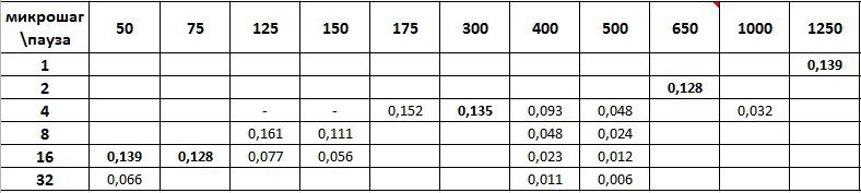
Horizontal is the size of the pause between steps in microseconds, vertically is the microstep mode. In the cells, the rotation speed in the angular measure per unit of time, obtained experimentally, corresponding to the specified mode and the specified pause value. The absolute value of speed in this case is not important (measured speed on the shaft attached to the motor through a worm gear and gearbox), the ratio between different cells is important.
It is easy to see that the maximum speed of 0.161 was achieved in the 1/8 microstep mode with an interval between steps of 125 microseconds (pure luck, at a full step, it would also certainly be possible to get it with an interval of about 1200). A slightly lower speed of 0.139 was obtained twice, in full step mode with an interval of 1250 microseconds, and in 1/16 step mode with an interval of 50 microseconds. A close speed of 0.135 was obtained in the 1/4 microstep mode with an interval of 300 microseconds. It turns out that when going from full step to 1/16 step to save the current speed, the interval between steps needs to be reduced exactly 25 times (but not 16!).
It is also clear that in the 1/32 microstep mode the maximum speed would be impossible to obtain. In this case, we are limited to the execution time of loop (), which on Arduino Uno is about 30 microseconds on an empty loop (at least it was on the “Chinese” where I conducted the experiments).
From all this it follows one simple conclusion - in our case it is reasonable to choose the microstep mode as much as possible, but considering the possible loss of torque. At maximum speed, we will not lose, smoothness and accuracy at low speeds will increase.
This is probably all. The application for Windows for remote control remained unlit - a software focus control panel. Perhaps set out in the 4th part, but for now there are doubts about the feasibility.
The first part is here , the second part is here .
This text is aimed at those who will understand the code for the purpose of its partial or full use and at those who solve similar problems and can learn something useful. The code is commented, so I will limit myself to a description of the structure and general logic, plus I will note important details.
Microcontroller code
The microcontroller code was developed and debugged in the Arduino 1.0.5-r2 environment, the latest version is available on githab ʻe .
')
Since the task of managing only one focuser was initially set forth, I did not use the features of the PLO. Only stepper motor control is allocated to a separate class in the StepperClass library.
Based on the task, the microcontroller should perform the following main functions:
- Initialize focuser - Setup ();
- Periodically remove the status of the buttons and the potentiometer from the remote control, control the status indication with the LEDs;
- Communicate with software on a laptop via RS232 - serialEvent () and SendCmd ();
- And control the stepper motor, rotating it at a given speed in a given direction, counting the steps taking into account the microstep mode, if necessary, controlling the output beyond the specified boundaries - StepperClass;
A few words about Loop ()
The potentiometer is polled at the interval specified in CheckSpeedTime (100 ms by default). The buttons interrogate each time, although this is of course redundant, you can also bind to CheckSpeedTime .
The motor rotates through a call to the global function Roll (), which translates it further to StepperClass.Roll (), while flashing the LED on the motorled pin.
When changing the current speed in any way, the brightness of the LED on the speedled pin changes .
With a sufficiently long inactivity (set in ReleaseTime ), the voltage is removed from the engine (SMs tend to actively eat the current and heat up). Undoubtedly, this option is "an amateur." In an amicable way, after precise focusing, the focus can not be touched. Ideally, it should be mechanically fixed, if it is provided for by the construction of the focus. If this is not done, then removing the current from the SM, we can get a small shift in the position of the focuser, that is, a small defocusing. In each particular case, it is necessary to check whether the stress relieves the focuser shift, and if so, turn off the automatic stress relief in the sketch and either manually remove it (having previously locked the focuser with the fixer), or not at all.
Lyrical digression on the topic of the SD library management
There are quite a few libraries that allow you to literally immediately start working with the SD, without understanding the details. I tried several different ones, most of all I liked AccelStepper . It is quite popular, has official offshoots, for example from Adafruit . For this and all such tasks, it is quite suitable, I used it for about half a year. The library is universal, it is not focused on any specific SD driver. During initialization, we specify the control pins - and more. Recommend!
But she also has flaws. Chief among them is no microstep support. In a number of tasks, this is extremely inconvenient. The speeds in the library are set in revolutions per second, and the position in steps. Obviously, if we change the micro-step mode, we will get a different speed, and the wrong position. If the microstep mode does not change - do not worry, once we introduce the correction factors. But if the micro-step mode dynamically switches, the situation becomes much more complicated. One option is to make a wrapper, which remembers the mode and automatically recalculates the coordinates and speeds. What I did for the time being.
In this project, the use of AccelStepper is quite acceptable and justified. I encountered some oddities and at least one bug (if you set the speed to 0 and take a step - the control does not return, we hang), but in general - I recommend to use it.
Developing your own class for controlling the SD is a forced step. In another project, working with a microstep became critical for me, and how much time I wrote my library was much simpler, but with microstage support and focused on working with the Polulu driver line (A4988, DRV8825). The library is very small, posted on github , the heading text contains comments.
The library will be updated and updated. In honesty, there are plans for substantial refinement of the Roll () function in order to improve the accuracy and smoothness of the course (taking into account the steps missed in time , the “catch up” mode).
I did not want to use different libraries in close projects, so the focuser was also transferred to StepperClass.
And one more lyrical digression about units
In this case, accurate knowledge of the rotation speed gives the user absolutely nothing. It is possible to draw an analogy with the volume control in everyday life - to us it does not matter in what units this or that pen, linear scale or logarithmic one. It is important to us that if the slider at the bottom is quiet, and at the top it is loud.
In this project, I decided not to complicate life and adhere to the same principle. As such, the speed is not calculated at all. Left quickly, right - slowly. While the microcontroller code everywhere operates not with speed, but with the interval between the steps of the engine, which in practice is somewhat more convenient.
In this project, I decided not to complicate life and adhere to the same principle. As such, the speed is not calculated at all. Left quickly, right - slowly. While the microcontroller code everywhere operates not with speed, but with the interval between the steps of the engine, which in practice is somewhat more convenient.
RS232 Concentrator Control Protocol
I did not find anything standard or generally accepted in the management of focusing devices (although I honestly did not dig deeply). In the future, I plan to write an ASCOM driver and use it with BackyardEOS, and with something else I hardly have to integrate. Therefore, I decided to use my very simple protocol:
| 168 | Team ID (1 byte) | command parameter | 13 | ten |
There is no checksum, the command size is unlimited (only a reasonable size of the receive buffer is 255 bytes) and is not predefined in the package. When a command is received, the buffer accumulates until the end ID of command # 13 # 10 arrives. After that, the command ID and the command parameter are allocated from the buffer and the command is executed. Omitting the ID of the beginning or end of a command may result in the omission of one command. In practice, this is not critical. I will describe the commands and parameters in more detail in the next section, here it is not so important.
Any command received is necessarily confirmed either by a response (for example, if it was a speed request, then the same command identifier is used), or by confirmation of the execution of the action (then there may be several packages with different identifiers).
All commands except FOCUSER_GO_TO_POSITION are executed immediately. The transition to a given position is performed in the main loop, so this operation can be performed for a long time, but we need to keep the possibility of canceling the operation.
In fact, the protocol completely simulates the operation of the remote control and even a little more.
The subtleties of adaptation and configuration, as well as some rakes
Current adjustment on A4988 and skip steps
The SD driver A4988 has a built-in current limiter supplied to the SD. The stuff is very useful and important. How to use it is described on the developer's site . But she has one interesting effect. As we know, when the current decreases, the torque drops. Strangely enough, specifically on the A4988 in the microstep mode, this can be expressed in the regular 100% skipping of steps at a certain phase. Therefore, in the 1/16 mode, you can easily get together 16 steps, only 4, or 8. Add current - and everything is fine.
Stepper Connection
When connecting the SD to the driver, it is advisable not to confuse the taps between the pairs (see bipolar SD connection diagrams). To confuse the bends inside the pair is not scary, get the rotation in the other direction. I recommend the first thing to ring a pair of taps and check the resistance of the windings, if it matches what was promised to you.
Once I was sold a SD for a nominal voltage of 12V, but it turned out that in fact it was designed for 2.8V. And I was surprised - why he somehow walks strangely with me, the driver heats up, the arduink sometimes turns off ...
Maximum rotation speed, pause between steps and microstep
Any SD has a maximum rotation speed. Usually - this is hundreds of revolutions per second. From the point of view of controlling the SD, this means that there is a certain minimum time interval between steps. Trying to take steps in the thicket is not only useless, but even harmful - the SD will twitch, whistle, buzz, but will not walk normally. This is another opportunity to get SD, not wanting to walk normally. The manufacturer does not always indicate the maximum speed, so it is quite likely that it will have to be determined by practical consideration.
An important and interesting point, which is usually not written about - how the use of microstep mode affects the maximum speed and the minimum duration of the pause between steps, respectively. The answer is - the use of microstep has almost no effect on the maximum rotational speed. At least, not essential in this work. But the duration of the pause between steps is very much affected. The smaller step we use, the more often we need to give a command to the next step. As an experiment, I tested one of my engines and got this picture:
Horizontal is the size of the pause between steps in microseconds, vertically is the microstep mode. In the cells, the rotation speed in the angular measure per unit of time, obtained experimentally, corresponding to the specified mode and the specified pause value. The absolute value of speed in this case is not important (measured speed on the shaft attached to the motor through a worm gear and gearbox), the ratio between different cells is important.
It is easy to see that the maximum speed of 0.161 was achieved in the 1/8 microstep mode with an interval between steps of 125 microseconds (pure luck, at a full step, it would also certainly be possible to get it with an interval of about 1200). A slightly lower speed of 0.139 was obtained twice, in full step mode with an interval of 1250 microseconds, and in 1/16 step mode with an interval of 50 microseconds. A close speed of 0.135 was obtained in the 1/4 microstep mode with an interval of 300 microseconds. It turns out that when going from full step to 1/16 step to save the current speed, the interval between steps needs to be reduced exactly 25 times (but not 16!).
It is also clear that in the 1/32 microstep mode the maximum speed would be impossible to obtain. In this case, we are limited to the execution time of loop (), which on Arduino Uno is about 30 microseconds on an empty loop (at least it was on the “Chinese” where I conducted the experiments).
From all this it follows one simple conclusion - in our case it is reasonable to choose the microstep mode as much as possible, but considering the possible loss of torque. At maximum speed, we will not lose, smoothness and accuracy at low speeds will increase.
What needs to be changed in the sketch to adapt to another engine
- Maximum and minimum speed values. Set in MIN_SPEED_DELAY and MAX_SPEED_DELAY as the interval between steps in microseconds. You can grope empirically;
- Mikroshag. Set based on engine capabilities in DEFAULT_MS. If there is enough torque, it is better to leave 1/16;
- The number of steps per revolution is set in STEP_PER_REVOLUTION;
- Is it necessary to remove the voltage from the motor at idle and idle time in IsRelease and ReleaseTime, respectively.
This is probably all. The application for Windows for remote control remained unlit - a software focus control panel. Perhaps set out in the 4th part, but for now there are doubts about the feasibility.
Source: https://habr.com/ru/post/245653/
All Articles