A simple built-in woofer amplifier on a chip with an FM receiver based on Arduino
Based on the Arduino creates a lot of interesting devices and systems. But not so many of them are used in real life. In most cases, these are toys or just projects just for fun. An even greater rarity is projects that are related to high-quality sound reproduction.
At the same time, on Arduino you can implement quite decent audio projects for everyday use. What we did, creating a high-quality stereo amplifier with built-in FM-receiver and control system. Actually, without a FM receiver, you can do without, and connect other sound sources. But we found this combination convenient. Plus, I wanted to make the project self-sufficient - it turned on, played, enjoy it. We already get.
According to the plan, the amplifier should provide very high sound quality at low power. In principle, for a house (and the system was conceived as a home one), 2 20 watts would suffice. And the neighbors will treat you well, and the sound will be very worthy.
What did we use?
- D-Class Digital Amplifier, 2 x 20W SANYO.
- Hi-Fi audio processor (TDA8425)
- FM radio.
- Real Time Clock (RTC).
- 2 valcoder with handles.
- Executive element (BM146).
- Module for connecting a character display (IIC LCD).
- Freaduino UNO, 3.3V / 5V, ATMEGA328, 16 MHz.
- IFK remote control with receiver.
Arduino controller can be used, in principle, any.
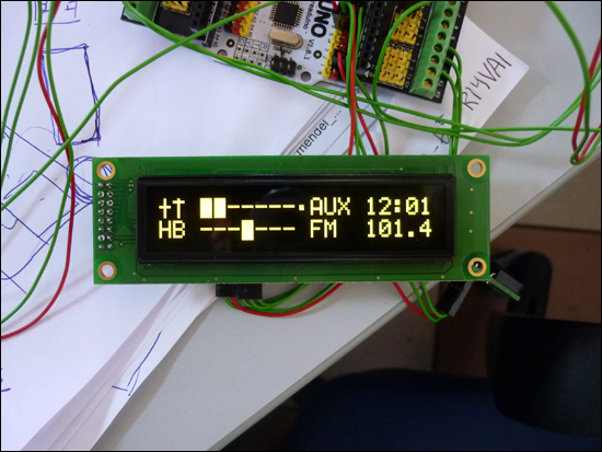
We took the display WEH002002ALPP5N00001 - it turns out very nice. If you are indifferent to beauty, try LCD for Arduino.
Still need a power supply. We used the PS-65-15 - 65W power supply. 15B. Enough for our purposes. Actually you can use any 9-15 volts and a power of 40 watts.
Well, and another red LED - everyone will do.
')
Software and sketch
(download links)
Sketch
Libraries
Library for IIC LCD Ardiuno1.0
Library for IIC LCD last
How to connect elements to Arduino?
The scheme is quite simple, so let's do the text.
OLED display with IIC LCD module installed:
C ---> 2
D ---> 3
L ---> 4
Valkoder (from the MP1093 set) left:
A ---> A0
B ---> A1
S ---> 9
+ food
Valcoder (from MP1093 set) right:
A ---> A2
B ---> A3
S ---> 10
+ food
Light-emitting diode:
---> 6
MP1094:
signal ---> 7 (first contact square pad)
on MP1094 signal arrangement:
1 signal
2 GND
3 VDD
Relay:
---> 8
MP1095:
SDA ---> A4
SCL ---> A5
+ food
MP1090S:
SDA ---> A4
SCL ---> A5
IN_SEN ---> VDD
IN_RST ---> 13
These signals are mapped to the 10-pin MP1090S connector.
The location of the signals on the connector:
- 1 (marked with a square pad) - SDA
- 2 SCL
- 3 IN_SEN
- 4 IN_RST
MP1243:
SDA ---> A4
SCL ---> A5
input 1 ---> AUX
input 2 ---> FM
The modules MP1090S and MP1243 need to be powered from the Arduino.
Control
The functions of the amplifier are used by two valcoders, with buttons on the axis. The right valcoder controls both the volume and the selection of the AUX / FM sound source.
The left valcoder controls the timbre (low-high), the balance, the choice of the frequency of the station, the clock (as without them?).
Here is how it looks and works:
We prefer to make enclosures of PVC, and now we are just making an excellent enclosure for an amplifier.
The device turned out really high quality, and the power is enough to enjoy the sound in a room whose area does not exceed 40 square meters. Do you have more? Next time we will publish an article about creating a more powerful amplifier.
If someone wanted to go home with such an amplifier, then the above elements can be found here or in any other place where peripherals for the Arduino are sold.
If you implement this project, we will be happy for ideas and suggestions for its improvement.
Source: https://habr.com/ru/post/245517/
All Articles