Worthy built-in digital amplifier LF do-it-yourself for reasonable money
Good afternoon, Habr!
Our previous article on DIY audio technology caused quite a resonance and today we would like to talk about our other development in the field of audio - high-quality ULF. The device was created by Oleg Tetushkin for their own needs. But as a result, the amplifier got accustomed in the office. It is collected, of course, from the fact thatit was badly lying on hand at the warehouse. In this case, it is assembled in a makeshift case. But in fact, it can be embedded anywhere - even in the furniture. What is enough fantasy.
In the comments to the above article, a controversy broke out about what can and cannot be called HiFi or even simply quality. Therefore, I would like to clarify that the definition of “quality” is based solely on our sense of beauty. We believe that the sound of this amplifier is quite decent and will satisfy any average person. Although audiophiles may have a different opinion about this.
')
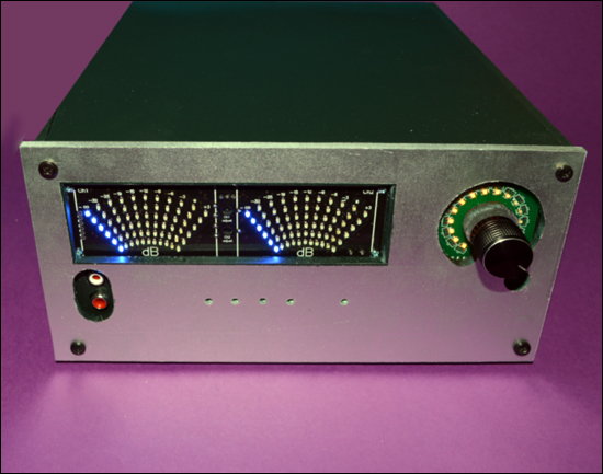
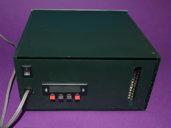
Such a handsome man should be the result.
What was used:
How it works?
For the MP5613, a 24V power supply unit was used, therefore, about 70 watts per channel will be given to the load of 4 ohms. The result - we get 2 * 70 watts of high-quality sound PurePath.
MP1231 (build on the AD8402) are installed at the input of the amplifier, for operation with the volume and balance control of the stereo channels, plus the MP5630I2, which is used as a pre-amplifier. After this stage, the stereo signal goes to the input of the MP5613, and only then to the speaker systems. As for the signal for the light-dynamic arrow indicator, we remove it from the output of the power amplifier, directly from the speaker systems.
Volume adjustment on the MP1231. Basic layout
We start the process with the MP1231 + MP5630I2 input cascade.
First, we connect potentiometer MP1231 immediately before MP563012 (this is shown in the diagram . To achieve our plans, on the reverse side of the MP563012 board, immediately after the RCA connector (Fig. 1 and 1.2), the signal conductors on the printed circuit board should be cut, stripping both conductors from both sides The cut is made so that you can install a potentiometer here.An important detail: you must use a shielded wire to connect the potentiometer and the preamplifier.Connect all the elements (probably, you can’t talk about this on Habré It should be fully complied with both the color and the marking.
And the power to the MP1231 is fed from the MP563012. Figure 2 shows this:

Pic1
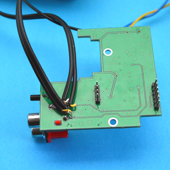
Fig.1.2
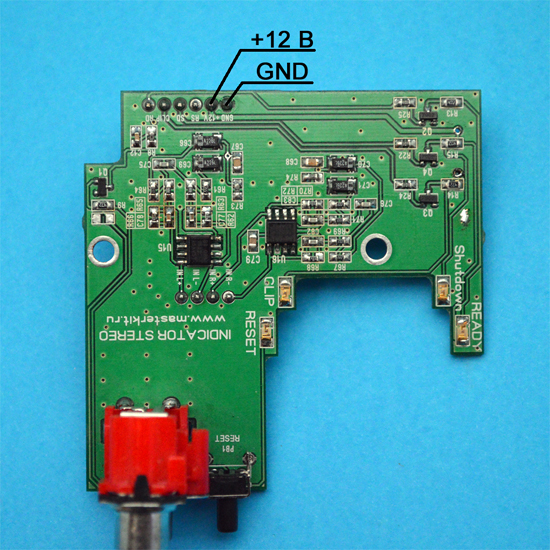
Fig. 2
Comment : In order to improve the noise immunity of the system (MP1231 is good for everyone, except for noise immunity), it is necessary to modify the circuit a little. To solve the problem, you must perform four simple steps (shown in Fig. 3):


Housing and display of indicators on the front panel
Before you start building the case, you need to slightly modify the MP5613 amplifier and the indicator MP563012. The refinement consists in soldering output channels to the boards, on wires with a length of 10-12 centimeters. As for the configurator boards, there are 6 LEDs installed, which indicate the status of the amplifier: temperature modes (2), error, readiness, overload and reset. After completion, all this can be inserted into the front panel of the device:
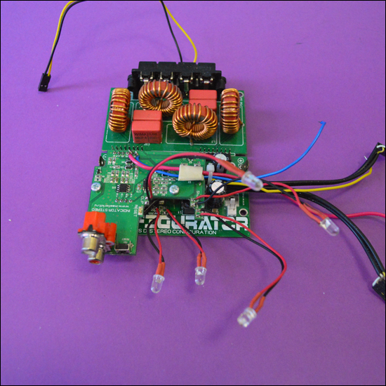
In addition, on the back of the configurator board, you need to solder a 15-20 centimeters long wire. The wire is soldered to one of the outputs (any one can be used) of each channel, through 0.1 μF film capacitors. Thus, the removal of the signal to the level indicator is organized.

Now proceed to the creation of the body
We cut it and glued it from PVC foam sheets. We liked this material because it is very easy to process, plus you can glue it with any plastic adhesive. Such material is easily painted. Here you can download the front and false panel files (.lay format).
Sizes of parts:
We decided to paint the body with a paint from a usual spray. The front panel was painted to look like metal, and the case itself was painted dark green (almost black). We fasten the indicator and regulator modules with screws M3 on the case.
Under the clamps acoustics cut a hole under the switch, plus we drill holes for clamps acoustics.
The power supply, which is logical, we put on the long side.
The amplifier is mounted on the bottom through the rack 5 mm. We fix the front panel with wood screws.
Comment. In order to completely eliminate interference from PWM modulation, perform the following steps:
Now you can connect powerful speakers and enjoy high-quality sound.
If you wish, you can upgrade the design of the structure. Here is a video demonstrating the work of all that happened:
We have made the amplifier for a long time, and it still serves us faithfully. Perhaps you can advise how to make the design better? The amplifier turned out great, but there is no limit to perfection, it has long been known.
If someone wants to repeat our path and over the weekend to get a very decent amplifier, here is all his electronic stuffing. As for the case, it is a matter of taste and the presence of auxiliary material.
Your Master Keith
Our previous article on DIY audio technology caused quite a resonance and today we would like to talk about our other development in the field of audio - high-quality ULF. The device was created by Oleg Tetushkin for their own needs. But as a result, the amplifier got accustomed in the office. It is collected, of course, from the fact that
In the comments to the above article, a controversy broke out about what can and cannot be called HiFi or even simply quality. Therefore, I would like to clarify that the definition of “quality” is based solely on our sense of beauty. We believe that the sound of this amplifier is quite decent and will satisfy any average person. Although audiophiles may have a different opinion about this.
')
Such a handsome man should be the result.
What was used:
- MP5613 - Digital amplifier D-class power of 2 x 150 watts. PurePath HD technology.
- MP5630I2 - Indicator for a powerful bass amplifier (stereo).
- MP1054 - Dynamic arrow indicator of the signal level.
- MP1231 - Audio Controller 2 Channel.
- ESE150-24 - Power supply. 150 watts. 24 V.
- SL-01H - Heatsink with fan.
- WP4-18FB - Push pin terminal 4 pins
- 5mm LEDs - 7 pcs.
How it works?
For the MP5613, a 24V power supply unit was used, therefore, about 70 watts per channel will be given to the load of 4 ohms. The result - we get 2 * 70 watts of high-quality sound PurePath.
MP1231 (build on the AD8402) are installed at the input of the amplifier, for operation with the volume and balance control of the stereo channels, plus the MP5630I2, which is used as a pre-amplifier. After this stage, the stereo signal goes to the input of the MP5613, and only then to the speaker systems. As for the signal for the light-dynamic arrow indicator, we remove it from the output of the power amplifier, directly from the speaker systems.
How to do it?
Volume adjustment on the MP1231. Basic layout
We start the process with the MP1231 + MP5630I2 input cascade.
First, we connect potentiometer MP1231 immediately before MP563012 (this is shown in the diagram . To achieve our plans, on the reverse side of the MP563012 board, immediately after the RCA connector (Fig. 1 and 1.2), the signal conductors on the printed circuit board should be cut, stripping both conductors from both sides The cut is made so that you can install a potentiometer here.An important detail: you must use a shielded wire to connect the potentiometer and the preamplifier.Connect all the elements (probably, you can’t talk about this on Habré It should be fully complied with both the color and the marking.
And the power to the MP1231 is fed from the MP563012. Figure 2 shows this:
Pic1
Fig.1.2
Fig. 2
Comment : In order to improve the noise immunity of the system (MP1231 is good for everyone, except for noise immunity), it is necessary to modify the circuit a little. To solve the problem, you must perform four simple steps (shown in Fig. 3):
- Directly to the power terminals of the MP1231, together with the supply conductors, clamp the electrolyte at 1000 μF or more.
- Electrolyte 470 microfarad solder parallel to the capacitor C4.
- The housing of the valcoder at MP1231 is connected to GND. Clean the mask next to the body leg and disappear.
- Connect GND MP1231 and GND amplifier driver with a thick wire can even be braided. This must be done because the 12V source is installed on the driver. How best to do this is shown in Fig.4.
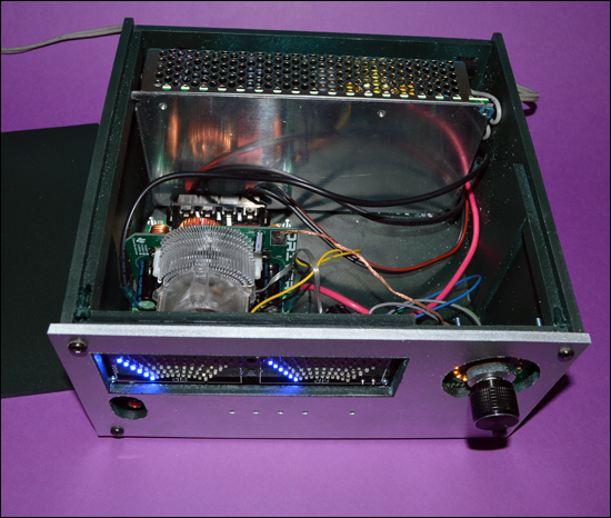
Housing and display of indicators on the front panel
Before you start building the case, you need to slightly modify the MP5613 amplifier and the indicator MP563012. The refinement consists in soldering output channels to the boards, on wires with a length of 10-12 centimeters. As for the configurator boards, there are 6 LEDs installed, which indicate the status of the amplifier: temperature modes (2), error, readiness, overload and reset. After completion, all this can be inserted into the front panel of the device:
In addition, on the back of the configurator board, you need to solder a 15-20 centimeters long wire. The wire is soldered to one of the outputs (any one can be used) of each channel, through 0.1 μF film capacitors. Thus, the removal of the signal to the level indicator is organized.
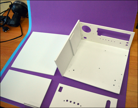
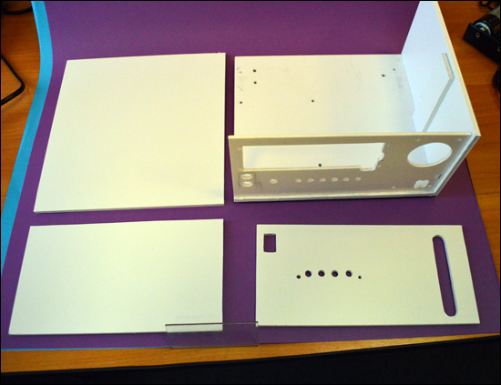
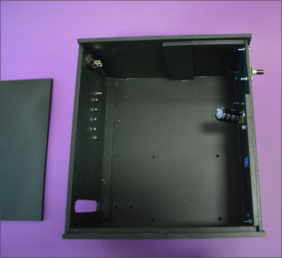
Now proceed to the creation of the body
We cut it and glued it from PVC foam sheets. We liked this material because it is very easy to process, plus you can glue it with any plastic adhesive. Such material is easily painted. Here you can download the front and false panel files (.lay format).
Sizes of parts:
- side walls - 110 * 200
- bottom and cover - 210 * 200
- back wall - 210 * 100
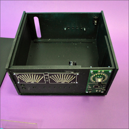
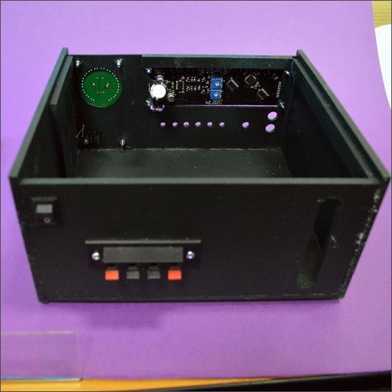
We decided to paint the body with a paint from a usual spray. The front panel was painted to look like metal, and the case itself was painted dark green (almost black). We fasten the indicator and regulator modules with screws M3 on the case.
Under the clamps acoustics cut a hole under the switch, plus we drill holes for clamps acoustics.
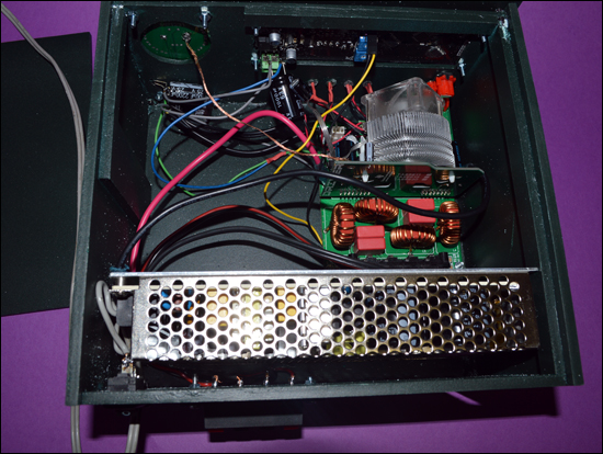
The power supply, which is logical, we put on the long side.
The amplifier is mounted on the bottom through the rack 5 mm. We fix the front panel with wood screws.
Comment. In order to completely eliminate interference from PWM modulation, perform the following steps:
- We connect in series GND of all involved modules either with thick wire or braid;
- We attach electrolytes 1000 microfarads or more to the power connectors of each module.
Now you can connect powerful speakers and enjoy high-quality sound.
If you wish, you can upgrade the design of the structure. Here is a video demonstrating the work of all that happened:
We have made the amplifier for a long time, and it still serves us faithfully. Perhaps you can advise how to make the design better? The amplifier turned out great, but there is no limit to perfection, it has long been known.
If someone wants to repeat our path and over the weekend to get a very decent amplifier, here is all his electronic stuffing. As for the case, it is a matter of taste and the presence of auxiliary material.
Your Master Keith
Source: https://habr.com/ru/post/245341/
All Articles