Navigation in rooms with iBeacon and INS
Imagine that you have been given the task of implementing indoor navigation. Accordingly, GPS / Glonass and similar satellite navigation systems are not available to you. What to do? In this article, we will examine in detail the solutions to such problems in the theoretical part, and in the practical, we will implement an indoor tracker for hardware to work with iBeacon beacons via Bluetooth BLE on NodeJS based on the latest Intel Edison platform, consider the use of trilateration and a filter Kalman, CylonJS library for working with sensors on NodeJS.
Part 1. Theory
1.1. The urgency of the problem
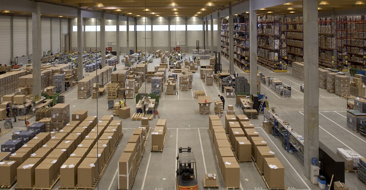
Recently, the problem of indoor navigation, as well as the provision of services based on their location (LBS - Location-based service) and preferences, has become increasingly urgent. Buildings are becoming more voluminous and often have a rather complicated structure, which can be oriented only by those who constantly visit such buildings, and for an unprepared person, orientation in such places turns into torture.
In addition, the solutions used in indoor-navigation (indoor navigation) also help in orientation outside buildings, on the street - where the use of satellite navigation systems is difficult in dense building conditions (there are no satellites in direct view, only reflected / weakened (noisy GPS / Glonass signal, etc.). Especially this problem is relevant for Japan with a high density of urban development.
')
In the case of satellite navigation (GPS / Glonass), there are OutDoor services, thanks to which you will learn about the nearest cafes / restaurants / hotels, etc. because your current location is known. And thanks to the indoor navigation service, you can easily and quickly find the nearest registration desk in the airport building, an exhibit in the museum (+ its description will immediately appear on the screen of your phone), a department and a shelf with the goods you need in the store (no longer have to spend hours on the search for all the necessary goods in the store), free parking space, and much more. A typical example is audio guides. Come to the museum, take the audio guide, and each time you are forced to search for the number of the desired exhibit, enter its number into the device and listen to its description. In the case of the use of indoor-navigation, everything is done automatically - just go to the exhibit you are interested in and its description will start playing without additional gestures on your part. No difficulties and wasted time, everything is simple.
Also, thanks to indoor-navigation, new tools for marketing appear - passing by your store, a person can instantly find out about promotions / events / services and goods you are holding, thanks to a pop-up message on your phone’s screen (so-called “Geo-fencing”, Moreover, the proposals offered to him will take into account his interests - because you can take into account information about his past purchases), or simply receive a notification when approaching a certain place (the second direction of indoor-navigation, called "Geo-aware"), and you - to receive statistical information ("heat maps" of visitors - a kind and very powerful offline analogue of Google Analytics), based on customer movements within your trading rooms (understand which departments and products are of increased interest - very easy). The market for such geocontext advertising (LBA - location-based advertising) is already measured in billions of dollars, and with the development of indoor-navigation systems its rapid growth is expected.
Due to the large commercial prospects, the direction of indoor-navigation is becoming increasingly popular and has already attracted the attention of such major players in the market as Google, Apple, Qualcomm, Broadcom, Sony, etc., and this, without a doubt, promising direction is already being invested hundreds of millions of dollars.
1.2. Solutions to the problem
We dealt with the urgency of the problem and the prospects, it remains to deal with its implementation. The main disadvantage of satellite positioning systems is the problematic nature of their use in closed rooms, as a result of which we have to look for other solutions to the problem of indoor navigation. There are several:
1) Navigate Wi-Fi. The existing infrastructure of communication networks is being used - Wi-Fi wireless networks points, and this is the least expensive option. The method of determining the coordinates is as follows: the user's device scans the available Wi-Fi access points, then sends information about them to the server, where this database data is compared with the coordinates of these access points, which are used to calculate the coordinates of the user. Unfortunately, the coordinates of Wi-Fi points are not exactly known, plus they may change (they moved the Wi-Fi point to another location or replaced it with another one - the coordinates are already wrong).
The accuracy with this approach leaves much to be desired (the error is up to 25 meters! And when using a specially created wi-fi infrastructure, the accuracy is 3-5 meters, but this already requires significant costs to create and maintain such a system), and to identify customers by Wi -Fi, tying their location to the map of the premises, is problematic - since iOS 8, the mac-addresses of Apple devices (iPhone, iPad) are constantly changing, to prevent “advertising” surveillance.
2) Geomagnetic positioning. Based on the orientation of the magnetic field of the Earth and is based on geomagnetic anomalies as criteria for geomagnetic positioning (anomalies arise due to heterogeneity of the geomagnetic field). It consists in fixing geomagnetic anomalies and plotting them on the map of the territory on which it is supposed to be oriented. In the future, navigation is performed on the map made by the device, in which the magnetometer is embedded. A practical example of implementation is the IndoorAtlas system of a team of scientists from the Finnish University of Oulu. The disadvantage is the high complexity of implementation, low accuracy. There are a lot of dynamically changing magnetic anomalies in the premises (wiring, the field in which changes depending on the connected load and greatly changes the configuration of the magnetic field around you, visitors with their electronic devices, racks, trolleys), greatly complicating the navigation, based on the specified method of orientation in space.
3) Satellite navigation systems (GPS / GLONASS, etc.) + inertial navigation systems (INS). It is applicable when the satellite navigation systems signal periodically appears - for example, traveling through a tunnel - when we enter the tunnel, we can still see the current coordinates and direction of movement from GPS / Glonass satellites, then when we enter the tunnel we lose the signal and use inertial navigation systems (ANN, based on an accelerometer, gyroscope, magnetometer), which uses as the initial conditions the latest actual data from the GPS / Glonass before losing communication with the satellite and maintains their relevance based on the sensor data about the current speed / acceleration / driving direction, before the resumption of communications with the satellites. It is necessary to take into account that in the INS errors constantly accumulate, and with time the data obtained from the INS become more and more different from reality.
4) Orientation on the base stations of cellular operators (GSM).
At least one GSM base station is constantly in sight of a cell phone / GSM modem, and usually several. The coordinates of these base stations are known (thanks to numerous navigation services, such as Yandex.Navigator, the application receives information about the base stations visible by your phone and your current position via GSM / Glonass, and sends this information to Yandex, where, based on this data, the base is base station coordinates, which is freely accessible through the provided API). We send the AT + CREG = 2 command to the modem, as a result of which we start to receive + CREG messages: with information about the currently connected base station - LAC and CELLID (respectively, the area code and the identifier of the base station). By sending this data to one of the special services (provided by Yandex, Google and other companies), we get the coordinates of this base station. Many modems allow you to get a list of visible base stations (BS) with their LAC and CELLID indicated - it remains only to get their coordinates through the database with the BS coordinates and to determine your approximate location using the triangulation method.
Cons - low accuracy (BS can be removed at a distance of 35 km from the user + some BS are mobile and constantly change their location).
5) Using Bluetooth beacons Becon - gives sufficient accuracy at an acceptable level of financial costs; A promising technology that is actively developing, so we will dwell on iBeacon in detail in the next section and implement it in practice.
6) Navigation based on synergistic effect - solves the problem of determining the current location, using all (or most) of the methods listed above. Efficiency is achieved due to the fact that we use several coordinate determination vectors at once, which helps to compensate for errors and improve the accuracy of determination of coordinates. By the way, last year a grant of $ 1 million was allocated by the Foundation for the Development of the Center for the Development and Commercialization of Skolkovo Technologies for the implementation of such a system.
1.3. Beacon technology
The scheme of work is simple - we have Bluetooth beacons installed along the entire perimeter, the coordinates of which we know. These beacons with a given periodicity produce a broadcast, containing their identifying information. The user application receives this data cyclically, determines the coordinates of the beacons using the database, and determines its location based on the signal strength (allowing to determine the distance from each of them).
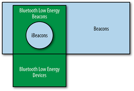
These beacons are often called iBeacon beacons, which is a mistake. It is more correct to call them Beacon-beacons, since iBeacon is the name of Apple's standard for use in iOS mobile applications, and Beacon is the actual physical implementation of beacons:
Consider more Beacon-maca.
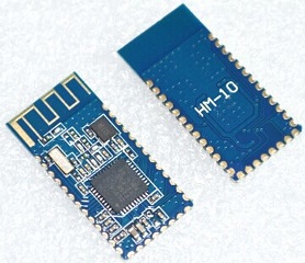
In terms of the physical implementation, the Beacon beacons are conventional Bluetooth 4.0 LE (Low Energy) devices, so their role can be successfully performed by any device equipped with a BLE chip — for example, Android-based smartphones, as well as iPhone, iPad, conventional laptops, Raspberry Pi with usb bluetooth dongle, etc., on which a special application is installed that implements the functions of the Beacon-beacon. The typical Beacon beacon shown in the figure above has rather compact dimensions and is capable of working from only one battery to two years. The circuit consists of a battery and a Soc (Systen-On-Chip) Texas Instruments CC2540 / 2541 (also used by the Nordic nRF51822), which is an 8051 microcontroller, which loads the firmware to implement the Beacon-Beacon function, and a peripheral Bluetooth LE module. The range of the beacon - an average of 10 meters (varies from 15-20cm to 25-40m depending on the model and settings). The periodicity of the data output is 200ms, but again, as a rule, it is configured - you can adjust it to a more frequent frequency, and to a rarer one. The service life of one battery - depending on the model from a little less than one year to three years (on average - 2 years). The price of one beacon is about 15-20 dollars. The beacon is a simple device that only broadcasts its data to everyone in a row (in the advertising-mode), using the GATT Bluetooth profile (it doesn’t even need to connect to it), however, manufacturers, as a rule, make it possible to connect to a beacon for the purpose of its remote configuration (editing data transmitted on the air + frequency of data output and radiation power).
1.4. Application and safety of Beacon beacons.
In addition to the application areas discussed at the beginning of this article, Beacon beacons can be used, due to their miniature and long battery life on enterprises and in construction, to orient goods, personnel, and equipment. Also, the use of such beacons in cars is proposed. For example, a car can be one big beacon beacon, so you can implement features like “Where's My Car” - to search for cars in large parking lots.
But do not overestimate this technology and do not forget about the safety issues of its use. In some sources, I met an offer to use Beacon-beacons in a car to remotely open the barrier. A car, in which the Beacon-beacon-barrier is built in (at the entrance to the enterprise / garage, etc.), opens automatically. Here we need to remember that the technology does not provide any means of security, and nothing prevents the attacker from simply scanning in real-time broadcast, in order to detect the desired beacon, which will cause the opening of the barrier. Then it remains only to register the required pUUID, Major and Minor in your fake beacon, turn it on - and someone else’s barrier will rise (or the doors will open), opening the way for you to foreign territory. In this case, it is better to abandon the use of Beacon beacons and resort to the implementation of the interactive exchange code, with encryption, between the transmitter (machine) and the receiver (barrier), which will exclude the possibility of hacking.
Also, nothing prevents an intruder from disturbing your orientation through beacons pre-arranged in a room by exposing your fake, with your pUUID / Major / Minor, disrupting navigation in a room. Or, if the position of the cargo is determined by the beacon fixed on it, the attacker can put his own in the right place, with the data of the beacon on the cargo, and pick up this cargo.
Using this technology, keep this in mind, and use your own methods of protection.
1.5. Data format
Consider the format of the data produced by the beacon. With a given periodicity, cyclically, the beacon gives the same data set:
The general structure of the Bluetooth package is as follows:
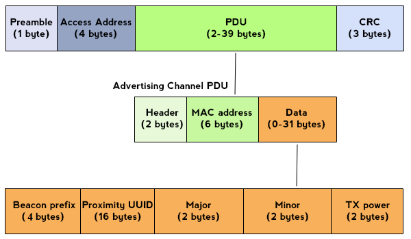
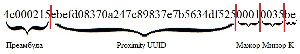
Preamble (4 bytes) is a packet prefix that allows to establish that we are dealing with a Beacon beacon. Always equal to 4c000215. The preamble consists of 4 fields: company identifier (2 bytes, in this example - 4c00), type (1 byte, in the example - 0x02) and data length (1 byte, value - 0x15).
Proximity UUID (16 bytes) - The identifier of the Beacon-beacon group. For example, we have several trading rooms in which you want to place lighthouses. In this case, in all these halls, the lighthouses will have the same UUID assigned by us, and this will allow us to distinguish our lighthouses from others, outsiders.
Major (2 bytes) - allows you to distinguish a small set of beacons within one group. That is, inside one large group of lighthouses, identified by a UUID, we may have several subgroups, each of which is identified by its major number. For example, in our example, each hall can be assigned its own major number. If the lighthouses need to cover several floors of the building - usually each floor is associated with its major number.
A minor (2 bytes) is a number identifying the beacon itself inside a major. The link uuid + major + minor allows us to unambiguously identify the beacon and from this data we can determine the coordinate of the beacon itself according to the coordinates of the beacons.
The following illustration gives a visual representation of the purpose of these identifying beacon parameters:

TX Power (parameter K in the figure above, 2 bytes) is the reference value of the beacon power, which is the signal strength at a distance of 1 meter from the beacon. It is measured and recorded in a beacon 1 time during its production. This constant is used when determining the distance from the user to the beacon. The first bit is a sign (1 - “-”, 0 - “+”). For example, TX Power in our example (see the figure above, the “K” parameter) is 0xBE. This is 190 decimal. Then the reference signal strength at a distance of 1m from the beacon is 256 - 190 = -66 dBm.
Let us dwell on determining the distance to the beacons. To determine our position in space, you need to know not only the coordinates of the beacons that we see (we can determine the coordinates based on pUUID / Major / Minor), but also the distance to them. This allows us to make the RSSI (Received Signal Strength Indicator) parameter calculated by the user's Bluetooth receiver based on the strength of the received signal. The higher the value of this parameter - the closer we are to the beacon. TX Power - this is RSSI, only the reference beacon measured by the manufacturer at a distance of 1 meter from it. To determine the distance to the beacon (in meters), the current RSSI value is used, and the reference TX Power for correction, as follows:
function get_distance(rssi, tx_power) { if (rssi == 0) { return -1; // } var ratio = rssi / tx_power; if (ratio < 1) { return Math.pow(ratio, 10); } else { return 0.89976 * Math.pow(ratio, 7.7095) + 0.111; } } 1.6. Determining the coordinates of the Beacon beacons.
To begin with, we need to place Beacon beacons in the room (for example, attach to double-sided tape to the wall / support posts, and the more of them and the beacons are closer to each other, the better will be the result of determining our coordinates) so that if possible, evenly cover the entire area of the room, and tie them to the coordinate grid on the room map (for the origin of coordinates, you can choose, for example, the angle of the room), taking into account the distance between the beacons each other:


We do not need geocoordinates, because we want to determine our location relative to the room, so we are attached to the coordinates inside the room itself. In the example above, the circles are the supporting pillars of the room, on each of which is fixed along the beacon. The room is limited to coordinates (0,0), (9.0), (9.7), (0.7). If the data of the beacons that are being fastened is unknown - you can launch an application on your smartphone that displays pUUID / Major / Minor beacons in sight (for example, for Android there is an iBeacon Locate) and make a similar map of the location of beacons.
At first glance, there is nothing difficult in determining our location - we scan Beacon beacons, determine their coordinates using the table (see figure above), calculate their distance from RSSI, and determine their location ... But from this moment the most interesting begins ...

Harsh reality makes its own adjustments. The fact is that even in the conditions of direct visibility with a beacon, the RSSI parameter “jumps”, randomly changing its value, as a result of which, without the use of a mathematical apparatus, determining the distance to the beacon becomes difficult. This is due to the following factors:
- Orientation and directional characteristics of radiation or reception of a beacon / user device antenna
- The presence of large shielding objects (man is also a person) in the direction from the beacon to the device
- The presence of nearby surfaces from materials that reflect the radio signal well, as well as a large accumulation of Beacon beacons in the same area, due to multipath interference with the main beam
To begin with, we need to somehow average the RSSI value from each of the beacons. To do this, set up beacons for data output with a maximum frequency (higher data output frequency - more data for averaging, respectively, and higher output accuracy, but take into account that with increasing data output frequency, you reduce the battery life of the beacon, so you need to search “Golden mean”), we accumulate them in the buffer, and with a certain periodicity (for example, once a second) we consider the average RSSI for each of the beacons accumulated in the data buffer (later on the basis of these “average” RSSI we will determine yat our position every second), then clears the buffer and the next second, again store data, and so repeatedly.
Then every second, after calculating the average RSSI, we select three beacons with the best average RSSI and determine our position in space using trilateration using the coordinates of these beacons. By the way, trilateration is often confused with triangulation , although this is not the same thing. In contrast to triangulation, in which the device coordinate is calculated based on the coordinates of the reference objects and the angles from each of them to the device, trilateration uses the known location of two or more reference objects and the measured distance between each of the reference objects (Beacon beacons) to calculate the location of the objects. and the device for which the location is determined. For accurate and unambiguous determination relative to the location of a point or object on a two-dimensional plane only using trilateration, as a rule, at least three reference points are required (information from three Beacon beacons with the best average RSSI).
It should be remembered that the calculations are performed in two-dimensional space (only two axes are X and Y), and the distance to the beacons here is three-dimensional, respectively, if the difference on the Z axis between the observer and the beacons is noticeable, you need to build projections on the X axis Y:

Here, A is the resulting distance through RSSI, B is the height of the beacon from our two-dimensional plane (where the observer is located — the device whose coordinates are determined), C is the distance to the beacon in this plane that we need to find. Since the formed triangle is equilateral, then, according to the Pythagorean theorem, we can easily find the required distance and use it in our calculations.
So, we have determined our location by three beacons using trilateration, but ... It's too early to rejoice. Even if we stand still - our location still “jumps”, but nevertheless, in practice, it was thus possible to obtain an accuracy of 3 meters.
For example, if you simply select the beacon with the best RSSI once per second, then with 10 consecutive measurements, we get a picture of the following plan (one grid division is 4 meters):

(red shows the position of the device, the coordinates of which are determined and from which the measurement is made, and the numbers in circles indicate the number of times the indicated beacon had the best average RSSI in 10 consecutive measurements). Accordingly, the triangulation gives us not quite an acceptable result.
Thus, further mathematical processing of the results is required, and here the Kalman filter comes to the rescue. The filter removes the measurement noise (random bursts) and gives the result, taking into account the results of current measurements, and taking into account the predicted results based on past measurements. The filter uses a dynamic model of the system (the law of motion) and 2 cyclically repeated stages: prediction and correction. At the first stage - prediction - we calculate the state of the system at the next point in time, and at the second stage - the adjustment - we adjust our forecast using the result of the next measurement:

More information about this filter can be found in the article Kalman Filter - Introduction I will only note that the filter has the ability to take into account the control action. For example, such a control action can be information from an accelerometer, which significantly improves the result (in this case, the error is no longer 3 meters in our case, but 1-1.5 is also not small, but due in part to the fact that the Kalman filter uses a system with given by the equation of motion, and we are dealing with chaotic motion). Those. The scheme is as follows: we consider the average RSSI -> choose 3 beacons with the best RSSI -> get the coordinate by trilateration -> feed the Kalman filter (along with the accelerometer readings as a control).
It is possible to reduce the error - use 2 systems at once - in addition to the basic positioning using beacon beacons, use an inertial navigation system consisting of an accelerometer, gyroscope and compass (magnetometer - its use is not necessary but highly desirable) to correct this position:
- Accelerometer - shows the projection of the acting forces. When the device is stationary or moving without acceleration, the accelerometer gives the values of the projections of the acceleration of gravity (gravity) on its axis.
- Gyro - shows the projection of angular velocities. When the device is motionless, we get zeros. When the angle of inclination of the device changes, the rotational speed spreads out on the axis.
- Magnetometer - shows the magnetic field strength, laid out on the axis.
Data from these sensors are not suitable for use in the "raw" form and also, as in the case of beacons, require mathematical processing, plus it is highly desirable to use a temperature sensor for thermal compensation, because MEMS gyroscopes have a rather noticeable temperature drift.
To use it is required to develop a degree of trust in one system or another. For example, to set that we, in determining coordinates, trust 90% of the INS (because the INS has a higher confidence level), and 10% - Beacon-beacons (that is, in the latter case, errors and jumps are much higher). With this option, using the INS, the accuracy of determining the coordinates can be improved to 20-30 cm (in general, the number of beacons also affects the accuracy of the coordinates - the closer they are to our device, the higher the accuracy, but the more expensive the implementation, beacons - not a penny thing).
In the next article we will look at the practical implementation of the Beacon tracker based on the new platform for creating Intel Edison IoT devices - we will write the application on NodeJS.
Source: https://habr.com/ru/post/245325/
All Articles