We raise the simplified provider network at home
 Initially, this article was a diary of laboratory work, which I came up with for myself. Gradually, I began to think that this information might be useful to someone else. Therefore, I tried to transform the note into a more or less decent appearance, add a description of some commands and technologies.
The article discusses the construction of a simple network with several providers and clients, in particular, technologies such as NAT, OSPF, BGP, MPLS VPN. Much, naturally, will be not considered. For example, the article contains almost no description of security problems, since one can talk endlessly on this topic, and the text is already quite voluminous. QoS is also set aside. under laboratory conditions, it is not particularly checked.
About the target audience. I am afraid that the newbies in the networks will not understand this article. People who have knowledge at least at the level of CCNP are not interested. Therefore, I am roughly guided by CCNA R & S certification.
Lab is built on the Cisco IOU emulator. Many things have already been written about its installation and use, so I will not repeat it.
')
Images of i86bi_linux-adventerprisek9-ms.152-4.M1 and i86bi_linux_l2-ipbasek9-ms.jan24-2013-B are used
We will decide on topology and IP addressing.
After some thought, I decided to make such a scheme:

It now remains to invent a legend:
- AS1234 is a major ISP1 provider. Owns the network 50.0.0.0/16.
- AS67 is an ISP2 provider. Owns a network of 100.0.0.0/16. Needed to add additional complexity to the topology.
- AS812 - Customer Customer1. Owns a block of PI-addresses IPv4 175.0.0.0/24, but within its network uses exclusively IPv6.
- AS65000 - Customer Customer2. Receives from the provider block of addresses 50.0.109.0/24. Inside the network uses private addresses from the subnet 192.168.109.0/24. AS65000 - private.
- AS1114 - Customer Customer3. Owns a block of PI addresses 150.0.0.0/24. They are also used for internal nodes.
For simplicity, on p2p links between routers in different ASs, we will use addresses like 200.0.xy.0 / 24, where x, y are the numbers of routers, x> y.
p2p links inside the providers will also have a / 24 mask (it is clear that this is waste, but it will be much easier to configure routing) and the form 50.0.xy.0 (100.0.xy.0 for AS67), where x, y are the numbers of the routers, x> y.
Initial setup
Basic configuration
To begin with, fill in all routers with approximately the same configuration (example for R2):
enable configure terminal We enable aaa and configure the ability to log in to the router remotely with local details:
aaa new-model aaa authentication login default local username cisco privilege 15 secret cisco no ip domain-lookup We set everything necessary for ssh v1.99 and allow it only in the line parameters:
ip domain-name isp1.com hostname R2 crypto key generate rsa modulus 2048 line console 0 exec-timeout 0 line vty 0 4 transport input ssh exec-timeout 0 On each router we will create several loopbacks. lo0 for routing protocols, the rest to simulate client connections, so that the RIB does not look too small. It is clear that if a provider owns a subnet 50.0.0.0/16, he has no right to announce, for example, a subnet 2.0.0.0/24, but for clarity, we will assume that this situation is possible:
interface loopback 0 ip address 2.2.2.2 255.255.255.255 interface loopback 1 ip address 2.0.0.2 255.255.255.0 interface loopback 2 ip address 2.0.1.2 255.255.255.0 interface loopback 3 ip address 2.0.2.2 255.255.255.0 interface loopback 4 ip address 2.0.3.2 255.255.255.0 Assign addresses and disable CDP on those interfaces that do not look at the AS-neighbor router:
interface ethernet 0/0 ip address 200.0.62.2 255.255.255.0 no cdp enable no shutdown interface ethernet 0/1 ip address 50.0.32.2 255.255.255.0 no shutdown interface ethernet 0/2 ip address 200.0.72.2 255.255.255.0 no cdp enable no shutdown interface ethernet 0/3 ip address 50.0.52.2 255.255.255.0 no shutdown end write Now you need to customize our customers.
HSRP, Stateful NAT
Let's start with AS65000. From it, the subnet 192.168.109.0/24 will be translated into the address block 50.0.109.0/24 issued by the provider. In this case, the autonomous system is connected to the same ISP through two routers, therefore, to ensure redundancy on them, you will need to configure HSRP. In this regard, when using conventional NAT, the problem of asymmetric routing may arise:
- The private address is broadcast to a public address on one of the routers.
- The answer comes to the second router.
- The second router has no translation rule for this packet, so it will simply drop the packet.
- To solve this problem, the official Cisco site suggests using Stateful NAT .

To begin, let's configure HSRP (config on R10).
Large companies rarely have just one VLAN, so we will do all the settings on the subinterface for 109 VLANs:
Create an HSRP group:
R10(config)#interface ethernet 0/1.109 R10(config-subif)#encapsulation dot1Q 109 R10(config-subif)#ip address 192.168.109.10 255.255.255.0 R10(config-subif)#standby 109 ip 192.168.109.109 R10(config-subif)#standby 109 preempt R10(config-subif)#standby 109 name SNAT Configure ACL and NAT pool for Stateful NAT in the same way as for normal (mask length 25, not 24, because it was decided to leave half the subnet for other needs, not considered here):
R10(config)#ip access-list standard SNAT_INSIDE R10(config-std-nacl)#permit 192.168.109.0 0.0.0.255 R10(config)#ip nat pool SNAT_OUTSIDE 50.0.109.1 50.0.109.126 prefix-length 25 Configure directly Stateful NAT:
R10(config)#ip nat stateful id 109 R10(config-ipnat-snat)#redundancy SNAT R10(config-ipnat-snat-red)#protocol udp R10(config-ipnat-snat-red)#mapping-id 109 R10(config)#ip nat inside source list SNAT_INSIDE pool SNAT_OUTSIDE mapping-id 109 overload And enable it on the interfaces:
R10(config)#interface ethernet 0/0 R10(config-if)#ip nat outside R10(config)#interface ethernet 0/1.109 R10(config-subif)#ip nat inside On eth 0/2 is applicable so that if the packet arrives at R10 and R5 is not available, the address is still broadcast and reaches the destination:
R10(config)#interface ethernet 0/2 R10(config-if)#ip nat outside You can do it differently - do not apply ip nat outside on eth0 / 2 of router R10, but ip nat inside on eth0 / 1 of router R9. The result will be exactly the same, the main thing is to understand why it is done and how it works.
On R9, the configuration is similar.
The configuration of SW13 is not given due to its simplicity. The interfaces looking at routers we will make trunks with encapsulation in 109 VLAN. We will also configure the interface in 109 VLAN'e to test our solution.
After this, it is possible to raise the routing on routers R3, R4, R5, R9 and R10 in such a way that the ping goes along this path:

SW13#ping 3.3.3.3 Type escape sequence to abort. Sending 5, 100-byte ICMP Echos to 3.3.3.3, timeout is 2 seconds: !!!!! Success rate is 100 percent (5/5), round-trip min/avg/max = 1/3/6 ms R9#sh ip nat translations Pro Inside global Inside local Outside local Outside global icmp 50.0.109.4:35 192.168.109.13:35 3.3.3.3:35 3.3.3.3:35 --- 50.0.109.4 192.168.109.13 --- --- R10#sh ip nat translations Pro Inside global Inside local Outside local Outside global icmp 50.0.109.4:35 192.168.109.13:35 3.3.3.3:35 3.3.3.3:35 --- 50.0.109.4 192.168.109.13 --- --- As we see, the information was synchronized between the two HSRP routers, and in asymmetric routing, the ping passed back through the router that did not perform the live address translation.
IPv6, NAT-PT
Now we turn to AS812. Recall that local engineers are actively introducing innovations, so the entire internal network is built on the IPv6 protocol. Nevertheless, the provider to which this company is connected did not even hear about the existence of IPv6, so you will have to use NAT-PT (Protocol Translation) on the border router.
This technology, as the name implies, allows broadcasting from one network protocol to another, and, accordingly, communicate to hosts that only support IPv6 or only IPv4 with each other.
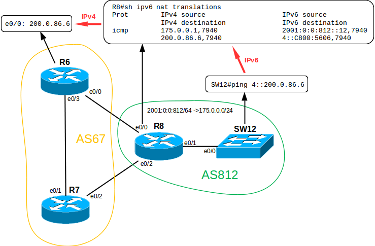
If we try to do this without a broadcast, we get something like this:
SW12#ping 200.0.86.6 % Unrecognized host or address, or protocol not running. Determine the addressing: suppose that one large subnet 2001 is used: 0: 0: 812 :: / 64
Then the address of the eth0 / 1 interface on R8 will be 2001: 0: 0: 812 :: 8/64.
Enable IPv6 packet routing:
R8(config)#ipv6 unicast-routing Set the IPv6 address:
R8(config)#interface ethernet 0/1 R8(config-if)#ipv6 address 2001:0:0:812::8/64 Enable NAT on interfaces:
R8(config)#interface range eth 0/0-2 R8(config-if-range)#ipv6 nat Create an IPv4 pool to which our internal IPv6 addresses will be translated:
R8(config)#ipv6 nat v6v4 pool 6TO4 175.0.0.1 175.0.0.254 prefix-length 24 The ACL containing the prefix, which, when entered, precedes the IPv4 address, we will inform the router that we need translation:
R8(config)#ipv6 access-list v6LIST R8(config-ipv6-acl)#permit ipv6 any 4::/96 Apply this ACL:
R8(config)#ipv6 nat prefix 4::/96 v4-mapped v6LIST And, in fact, enable NAT-PT:
R8(config)#ipv6 nat v6v4 source list v6LIST pool 6TO4 overload Note that the prefix length is 96 bits. If we consider that the total length of the IPv6 address is 128 bits, we get 32 bits in the remainder, which is equal to the length of the IPv4 address.
We are checking. Temporarily create the necessary routes on R6 and R8 and try to ping R6 from SW12 switch:
SW12#ping 4::200.0.86.6 Type escape sequence to abort. Sending 5, 100-byte ICMP Echos to 4::C800:5606, timeout is 2 seconds: !!!!! Success rate is 100 percent (5/5), round-trip min/avg/max = 1/1/3 ms As we can see, the technology works. In order for a dedicated subnet 175.0.0.0/24 not to be wasted in vain (it’s still extremely stupid to buy PI addresses and use them only for dynamic NAT) you could configure static broadcasts of v6v4 and v4v6 so that, for example, an internal server having an IPv6 address was accessible from the external network by IPv4 address. However, we will not do this.
More, at the moment, customers have nothing special to configure, so you can proceed to configure routing.
OSPF, autonomous system routing configuration
Let's start with IGP, in particular with the OSPF protocol. EIGRP will not be considered, because on such small networks there are few fundamental differences in configuration.
In the ISP1 provider’s network, all routers except R1 are connected on the principle “each with each”. Since R1 is connected with only one link, it makes sense to bring it into a separate totally stubby area (that is, to give R1 only the default route to R3).

Here is an example of setting up OSPF on R3:
R3(config)#router ospf 1234 R3(config-router)#router-id 3.3.3.3 By default, we will forbid all interfaces to participate in the OSPF process, and then enable only the necessary ones (specifically, on R3, these commands have absolutely no sense, since all of its interfaces will be involved):
R3(config-router)#passive-interface default R3(config-router)#no passive interface e0/1 R3(config-router)#no passive interface e0/2 R3(config-router)#no passive interface e0/3 R3(config-router)#no passive interface e0/4 The following command makes it possible to run the SPF process only partially when changing the network map, for a separate branch of the tree, which in large networks can somewhat reduce the time of topology convergence:
R3(config-router)#ispf Add the network to the dead end region and configure the region itself:
R3(config-router)#network 50.0.31.0 0.0.0.255 area 1234 R3(config-router)#area 1234 stub no-summary Add subnets from the backbone region:
R3(config-router)#network 50.0.32.0 0.0.0.255 area 0 R3(config-router)#network 50.0.43.0 0.0.0.255 area 0 R3(config-router)#network 50.0.53.0 0.0.0.255 area 0 You can, of course, announce the following:
R3(config-router)#network 50.0.0.0 0.0.255.255 area 0 but:
- There is a chance to accidentally capture an extra subnet;
- When removing one of the summed subnets, problems may arise;
- This in principle gives less control over the situation and increases the risk of error.
You can also declare that the subnet belongs to the ospf process directly on the interface (and this is the only way in IPv6), but the method I use is trite faster (in my opinion), and even clearer when the entire configuration associated with a particular protocol is stored in one place.
Networks with loopbacks add command redistribute connected. This must be done carefully, because there is always the risk of declaring something that we would not like to announce. Therefore, we will use the route-map to establish clear restrictions:
R3(config)#ip access-list standard REDISTRIBUTE_CONNECTED R3(config-std-nacl)#permit host 3.3.3.3 R3(config-std-nacl)#permit 3.0.0.3 0.0.0.255 R3(config-std-nacl)#permit 3.0.1.3 0.0.0.255 R3(config-std-nacl)#permit 3.0.2.3 0.0.0.255 R3(config-std-nacl)#permit 3.0.3.3 0.0.0.255 R3(config)#route-map REDISTRIBUTE_CONNECTED R3(config-route-map)#match ip address REDISTRIBUTE_CONNECTED R3(config-router)#redistribute connected route-map REDISTRIBUTE_CONNECTED subnets In general, the route-map is an extremely flexible and convenient technology that allows you to create almost anything with subnets: summing, hanging various tags, tags, changing various parameters, the paths of packets, etc. In the section on configuring BGP, I’ll touch on the route-map in a bit more detail.
Let us dwell in more detail on how the redistribute command stands out:
R5(config)#do sh ip route ----------------------------------------------------------------- 3.0.0.0/8 is variably subnetted, 5 subnets, 2 masks O E2 3.0.0.0/24 [110/20] via 50.0.53.3, 00:19:17, Ethernet0/0 O E2 3.0.1.0/24 [110/20] via 50.0.53.3, 00:19:07, Ethernet0/0 O E2 3.0.2.0/24 [110/20] via 50.0.53.3, 00:19:07, Ethernet0/0 O E2 3.0.3.0/24 [110/20] via 50.0.53.3, 00:19:07, Ethernet0/0 O E2 3.3.3.3/32 [110/20] via 50.0.53.3, 00:19:37, Ethernet0/0 ----------------------------------------------------------------- O 50.0.32.0/24 [110/20] via 50.0.53.3, 00:21:43, Ethernet0/0 O 50.0.43.0/24 [110/20] via 50.0.53.3, 00:21:43, Ethernet0/0 If we carefully look at the routing table, we see that the subnets created by the redistribute connected command are marked as external routes for this AS, unlike those added by the network command. Accordingly, R3 becomes an ASBR (Autonomous System Boundary Router), although in fact it is not.
Also, if the route type is E2 (and this label is set by default), the metric will not be recalculated, as it usually happens in the SPF process (that is, if the path to the subnet is increased, the cost of links will not be taken into account).
You can avoid this by:
R3(config-router)#redistribute connected route-map REDISTRIBUTE_CONNECTED subnets metric-type 1 Let's go back to R1. After configuring area 1234 as totally stubby in the routing table, we will see only one route coming via OSPF. As expected - this is the default gateway:
R1(config-router)#do sh ip route -------------------------------------------------------------- Gateway of last resort is 50.0.31.3 to network 0.0.0.0 O*IA 0.0.0.0/0 [110/11] via 50.0.31.3, 00:00:00, Ethernet0/1 ------------------------------------------------------------- All other routers in the lab are configured in approximately the same way, so there is no point in focusing on them.
BGP, setting up routing between autonomous systems
Recently, at an interview in one large and well-known integrator, I was asked the question: “Why do IGPs ever need when we have iBGP?”. The answer about the terrible speed of convergence of the protocol compared to IGP, the need for a full-mesh topology (or Route Reflector), the increased requirements for the resources of each router in the topology did not satisfy them.
Just coming out of the meeting room, I remembered that BGP will not place routes for which next-hop is unavailable in the RIB.
Accordingly, without IGP from internal routers, we will not be able to reach the next-hop (which, as a rule, is the eBGP address of the peer, which is not directly connected) and we will not be able to route it. I think that they wanted to hear from me exactly that. By the way, the position was offered to me after all, but this is a completely different story.
Now a little more about the neighborhood relationship. In fact, in a good way, it would be worthwhile to establish relationships between eBGP peers with the help of their loopback addresses. However, we do not have this urgent need. Each router is connected to each one with no more than one link; accordingly, fault tolerance will not be affected.
In order to reach the neighboring loopback for eBGP peers, we would need the following actions:
- Static route on neighbor's loopback;
- redistribute static in OSPF (you can do without it, if you do the next-hop self command on all iBGP peers, but somehow I don’t really like to do that);
- The neighbor nnnn ebgp-multihop 2 command in order to increase the ttl of the service BGP packets (1 by default);
- The neighbor nnnn update-source lo0 command.
To reduce the configuration we will use:
- loopback addresses for communication between iBGP peers (it really makes sense, because even if one of the links is dropped, the TCP session will remain alive thanks to redundant connections);
- addresses on physical interfaces for eBGP peers
Configure BGP in a standalone 1234 system.

For a start, a small checklist:
- prefix-list, filtering private networks;
- prefix-list filtering p2p links;
- prefix-list, filtering addresses on lo0;
- prefix-list, filtering the addresses announced by the neighboring AS;
- route-map for the neighbor;
- route-map for announcement of connected networks (if suddenly we don’t want to announce them with the network command);
- BGP configuration directly;
We will not use the community attribute. In this case, the network is small, peering wars are not foreseen, DDOS has nowhere to get, so confusion from the community, in my opinion, will be more than good.
Why do we filter at all? Then, if the client is inadequate and suddenly decides to announce everything he wants (in our case, the AS65000 will try to do just that), the provider MUST stop these actions on its part.
Let's go through the list. For example, we will configure R4:
1) Since this is just a laboratory, we will not filter all networks, but only the 3 most famous ones (there are still a bunch of prefixes reserved for different needs, for example 127.0.0.0/8):
R4(config)#ip prefix-list PRIVATE_IP permit 10.0.0.0/8 le 32 R4(config)#ip prefix-list PRIVATE_IP permit 172.16.0.0/12 le 32 R4(config)#ip prefix-list PRIVATE_IP permit 192.168.0.0/16 le 32 2) p2p links between routers inside the autonomous system, in my opinion, information that there is no need to disclose, so it’s best to leave it inside the AS:
R4(config)#ip prefix-list P2P permit 50.0.31.0/24 le 32 R4(config)#ip prefix-list P2P permit 50.0.32.0/24 le 32 R4(config)#ip prefix-list P2P permit 50.0.43.0/24 le 32 R4(config)#ip prefix-list P2P permit 50.0.52.0/24 le 32 R4(config)#ip prefix-list P2P permit 50.0.53.0/24 le 32 R4(config)#ip prefix-list P2P permit 50.0.54.0/24 le 32 3) Our lo0 addresses also should not be routed, because thus, we can harm the real host 1.1.1.1, or, for example, make the google DNS server unavailable with the address 8.8.8.8 (in fact, we cannot, for a long time all providers have been filtering networks with a mask of / 25 or more).
R4(config)#ip prefix-list LOOPBACK permit 1.1.1.1/32 R4(config)#ip prefix-list LOOPBACK permit 2.2.2.2/32 R4(config)#ip prefix-list LOOPBACK permit 3.3.3.3/32 R4(config)#ip prefix-list LOOPBACK permit 4.4.4.4/32 R4(config)#ip prefix-list LOOPBACK permit 5.5.5.5/32 4) Our neighboring AS65000 is not a transit one, therefore it can not announce anything except the subnet 50.0.109.0/24 issued to it. Check it out:
R4(config)#ip prefix-list ADVERTISED permit 50.0.109.0/24 le 32 This completes the filtering. I have never (at the time of writing this part of the article) worked at an ISP, but I have a very strong suspicion that they have several times more routes in BGP, and the goals for this can be very different.
5) It's time to set up a route-map. Since we wrote “permit” in the prefix sheets, now we will write “deny”.
Outbound filtering:
R4(config)#route-map AS65000_OUT deny 10 R4(config-route-map)#match ip address prefix-list LOOPBACK R4(config-route-map)#match ip address prefix-list P2P R4(config-route-map)#match ip address prefix-list PRIVATE_IP R4(config)#route-map AS65000_OUT permit 20 Filtering incoming traffic:
R4(config)#route-map AS65000_IN R4(config-route-map)#match ip address prefix-list ADVERTISED R4(config)#route-map AS65000_IN deny 20 6) On R4 we will add connected networks 4.0.0.0/24 - 4.0.3.0/24 summarizovanny in one subnet 4.0.0.0/22. This can be done in several ways, we will show one of them:
R4(config)#ip access-list standard REDISTRIBUTE_CONNECTED R4(config-std-nacl)#permit 4.0.0.0 0.0.3.255 R4(config)#route-map REDISTRIBUTE_CONNECTED R4(config-route-map)#match ip address REDISTRIBUTE_CONNECTED R4(config-route-map)#router bgp 1234 R4(config-router)#redistribute connected route-map REDISTRIBUTE_CONNECTED At this stage we get the following output #sh ip bgp:
R4(config-router)#do sh ip bgp ------------------------------------------------------------------- Network Next Hop Metric LocPrf Weight Path *> 4.0.0.0/24 0.0.0.0 0 32768 ? *> 4.0.1.0/24 0.0.0.0 0 32768 ? *> 4.0.2.0/24 0.0.0.0 0 32768 ? *> 4.0.3.0/24 0.0.0.0 0 32768 ? Now do
R4(config-router)#aggregate-address 4.0.0.0 255.255.252.0 summary-only and we see the following conclusion:
R4(config-router)#do sh ip bgp ------------------------------------------------------------------- Network Next Hop Metric LocPrf Weight Path s> 4.0.0.0/24 0.0.0.0 0 32768 ? *> 4.0.0.0/22 0.0.0.0 32768 i s> 4.0.1.0/24 0.0.0.0 0 32768 ? s> 4.0.2.0/24 0.0.0.0 0 32768 ? s> 4.0.3.0/24 0.0.0.0 0 32768 ? All routes, except for the total, are marked with the letter “s” - suppressed, which means suppressed. They will not be announced. If for some reason we had entered the aggregate-address command without the summary-only keyword, then we would have announced the sumrized subnet and each of the / 24 separately.
7) The time has come for setting up the BGP process itself, establishing neighbor relations and configuring other parameters describing the general nature of the protocol operation:
R4(config)#router bgp 1234 R4(config-router)#bgp router-id 4.4.4.4 R4(config-router)#neighbor 3.3.3.3 remote-as 1234 R4(config-router)#neighbor 3.3.3.3 update-source lo0 R4(config-router)#neighbor 5.5.5.5 remote-as 1234 R4(config-router)#neighbor 5.5.5.5 update-source lo0 R4(config-router)#neighbor 200.0.94.9 remote-as 65000 Let's apply the previously configured route-map to the neighbor:
R4(config-router)#neighbor 200.0.94.9 route-map AS65000_IN in R4(config-router)#neighbor 200.0.94.9 route-map AS65000_OUT out Now it's time to set up the R3.
Let's skip all the items about filtering, because R3 does not have eBGP peers. Instead, configure R3 as a Route Reflector . The fact is that when receiving a route, iBGP peers do not send it further. Thus, we must have a full-mesh topology so that, for example, R4 can get routes with R2.
Looking at our topology, you can see that it does not hold out a bit to the full mesh. Therefore, you will have to use Route Reflector so that all iBGP peers learn all the iBGP routes.
Since we have as many neighbors as 3, it makes sense to configure them using the peer-group:
R3(config-router)#neighbor LOCAL peer-group R3(config-router)#neighbor LOCAL remote-as 1234 R3(config-router)#neighbor 2.2.2.2 peer-group LOCAL R3(config-router)#neighbor 4.4.4.4 peer-group LOCAL R3(config-router)#neighbor 5.5.5.5 peer-group LOCAL R3(config-router)#neighbor LOCAL update-source lo0 Configure the group number for the Route Reflector (special attention should be paid to this if there are several clusters to be made):
R3(config-router)#bgp cluster-id 1 And we will make all our neighbors clients:
R3(config-router)#neighbor LOCAL route-reflector-client Please note that there is nothing to configure on the clients themselves, it is enough to specify the RR neighbor as a regular iBGP peer.
We also show on R3 the second way of summing up subnets.
Create a cumulative route to null 0 (recall that if the route is not in the RIB, BGP will not announce it):
R3(config)#ip route 3.0.0.0 255.255.252.0 null 0 And just add it to BGP:
R3(config-router)#network 3.0.0.0 mask 255.255.252.0 As we can see, the summarized network is present in the BGP table and announced. We also received from R4 its summarized network 4.0.0.0/22:
R3(config-router)#do sh ip bgp ------------------------------------------------------------------- Network Next Hop Metric LocPrf Weight Path *> 3.0.0.0/22 0.0.0.0 0 32768 i *>i 4.0.0.0/22 4.4.4.4 0 100 0 i It is not for me to judge which way of summarization is better, but the one we used on R4 is definitely more flexible in customization, so I prefer to use it.
As we remember, R1 is connected only to R3 and does not use BGP, so on R3 we need to announce the network 50.0.254.0/24 with R1 so that it is also available. Let's do it in the simplest way:
R3(config-router)#network 50.0.254.0 mask 255.255.255.0 It would seem that everything should go perfectly, the route is announced, but let's look at R4:
R4(config-router)#do sh ip bgp Network Next Hop Metric LocPrf Weight Path ------------------------------------------------------------------- r>i 50.0.254.0/24 50.0.31.1 20 100 0 i ------------------------------------------------------------------- We caught RIB-failure. In fact, absolutely nothing terrible happened. There are several reasons why RIB-failure can occur. In this case, this happened because in RIB on R4 there is already a route from the best AD (obtained through OSPF) to this prefix. Will this route be announced to other AS? The answer is yes, there will be nothing to worry about.
R9 ( , BGP ):
R9(config)#do sh ip bgp --------------------------------------------------------------------- Network Next Hop Metric LocPrf Weight Path *> 3.0.0.0/22 200.0.94.4 0 1234 i *> 4.0.0.0/22 200.0.94.4 0 0 1234 i *> 50.0.109.0/24 0.0.0.0 0 32768 i *> 50.0.254.0/24 200.0.94.4 0 1234 i --------------------------------------------------------------------- , , BGP R9 , 192.168.109.0/24 , R4:
R4#debug ip bgp 200.0.94.9 updates R9(config-router)#network 192.168.109.0 mask 255.255.255.0 R4# *Nov 28 22:13:31.004: BGP(0): 200.0.94.9 rcvd UPDATE w/ attr: nexthop 200.0.94.9, origin i, metric 0, merged path 65000, AS_PATH *Nov 28 22:13:31.004: BGP(0): 200.0.94.9 rcvd 192.168.109.0/24 -- DENIED due to: route-map; , R4 , route-map .
, R9 R10 , . , ( , , AS65000 ).
R5 R2 BGP:
R5(config-router)#neighbor 200.0.115.11 remove-private-as AS. , 50.0.109.0/24 ( AS 65000) R11:
R11(config-router)#do sh ip bgp --------------------------------------------------------------------- Network Next Hop Metric LocPrf Weight Path *> 3.0.0.0/22 200.0.115.5 0 1234 i *> 4.0.0.0/22 200.0.115.5 0 1234 i *> 5.0.0.0/24 200.0.115.5 0 0 1234 i *> 5.0.1.0/24 200.0.115.5 0 0 1234 i *> 5.0.2.0/24 200.0.115.5 0 0 1234 i *> 5.0.3.0/24 200.0.115.5 0 0 1234 i *> 50.0.109.0/24 200.0.115.5 0 1234 i *> 50.0.254.0/24 200.0.115.5 0 1234 i --------------------------------------------------------------------- path AS – 1234, , AS65000 .
, R11 . , AS1114 ISP, ( AS ). , - , AS , :
- , .. , ;
- a company that owns AS, because her uplinks will be crammed with alien traffic that is completely uninteresting to her.
I will not show how to do filtering on R11, conceptually this process is no different from what has already been described. I can only say that there will be such a team there:
R11(config)#ip prefix-list OUTBOUND permit 150.0.0.0/24 le 32 A little about why prefix lists are used everywhere, not ACLs:
- With a single prefix list, we can filter all subnets of a given network at once (for example, the command just above filters not only / 24 masks, but also all sorts of / 25, / 26, etc ...);
- I vaguely remember reading the article, which said that the prefix-list has a tree structure unlike the ACL, so the router needs a few less resources for the lukap (perhaps not true, I rely on memory, I can't find the article).
, BGP , , ( , - ).
sh ip bgp R8 :
sh ip bgp
R8(config-router)#do sh ip bgp ------------------------------------------------------------------------ Network Next Hop Metric LocPrf Weight Path * 2.0.0.0/24 200.0.87.7 0 67 1234 i *> 200.0.86.6 0 67 1234 i * 2.0.1.0/24 200.0.87.7 0 67 1234 i *> 200.0.86.6 0 67 1234 i * 2.0.2.0/24 200.0.87.7 0 67 1234 i *> 200.0.86.6 0 67 1234 i * 2.0.3.0/24 200.0.87.7 0 67 1234 i *> 200.0.86.6 0 67 1234 i * 3.0.0.0/22 200.0.87.7 0 67 1234 i *> 200.0.86.6 0 67 1234 i * 4.0.0.0/22 200.0.87.7 0 67 1234 i *> 200.0.86.6 0 67 1234 i * 5.0.0.0/24 200.0.87.7 0 67 1234 i *> 200.0.86.6 0 67 1234 i * 5.0.1.0/24 200.0.87.7 0 67 1234 i *> 200.0.86.6 0 67 1234 i * 5.0.2.0/24 200.0.87.7 0 67 1234 i *> 200.0.86.6 0 67 1234 i * 5.0.3.0/24 200.0.87.7 0 67 1234 i *> 200.0.86.6 0 67 1234 i * 6.0.0.0/24 200.0.87.7 0 67 i *> 200.0.86.6 0 0 67 i * 6.0.1.0/24 200.0.87.7 0 67 i *> 200.0.86.6 0 0 67 i * 6.0.2.0/24 200.0.87.7 0 67 i *> 200.0.86.6 0 0 67 i * 6.0.3.0/24 200.0.87.7 0 67 i *> 200.0.86.6 0 0 67 i * 7.0.0.0/24 200.0.87.7 0 0 67 i *> 200.0.86.6 0 67 i * 7.0.1.0/24 200.0.87.7 0 0 67 i *> 200.0.86.6 0 67 i * 7.0.2.0/24 200.0.87.7 0 0 67 i *> 200.0.86.6 0 67 i * 7.0.3.0/24 200.0.87.7 0 0 67 i *> 200.0.86.6 0 67 i * 50.0.109.0/24 200.0.87.7 0 67 1234 i *> 200.0.86.6 0 67 1234 i * 50.0.254.0/24 200.0.87.7 0 67 1234 i *> 200.0.86.6 0 67 1234 i * 100.0.0.0/16 200.0.87.7 0 0 67 i *> 200.0.86.6 0 67 i * 150.0.0.0/24 200.0.87.7 0 67 1114 i *> 200.0.86.6 0 67 1114 i *> 175.0.0.0/24 0.0.0.0 0 32768 i , R8 full view ( — full view).
:
SW12#ping 4::3.0.0.3 Type escape sequence to abort. Sending 5, 100-byte ICMP Echos to 4::300:3, timeout is 2 seconds: !.!.! Success rate is 60 percent (3/5), round-trip min/avg/max = 1/2/4 ms .
CEF R8 ( ). :
SW12#ping 4::3.0.0.3 Type escape sequence to abort. Sending 5, 100-byte ICMP Echos to 4::300:3, timeout is 2 seconds: !!!!! Success rate is 100 percent (5/5), round-trip min/avg/max = 1/1/3 ms MPLS VPN
MPLS , . L2 L3 VPN. R15.

( , ) MPLS ( AS67 P (Provider) , PE (Provider Edge), VPN). (R7 R11), :
MPLS , OSPF:
R7(config)#router ospf 67 R7(config-router)#mpls ldp autoconfig R7(config)#mpls ldp router-id loopback 0 :
R7(config)#mpls label range 700 799 MPLS :
R7(config)#mpls ip MPLS VPN , , - .
AS67 L2VPN R11 R15
VLAN R11 R15:
R11(config)#bridge irb R11(config)#bridge 100 protocol ieee R11(config)#bridge 100 bridge ip R11(config)#bridge 100 route ip R11(config)#int bvi 100 R11(config-if)#ip address 192.168.100.11 255.255.255.0 R11(config)#int eth0/2.100 R11(config-subif)#encapsulation dot1Q 100 R11(config-subif)#bridge-group 100 R11(config)#int eth 0/1.100 R11(config-subif)#encapsulation dot1Q 100 R11(config-subif)#bridge-group 100 And now enter just a few commands on PE:
R7(config)#int eth 0/3.100 R7(config-subif)#encapsulation dot1Q 100 R7(config-subif)#xconnect 6.6.6.6 100 encapsulation mpls R7(config-subif)#mpls ip All, L2 connectivity between VLAN 100 for R11 and R15 is up. Check:
SW14#ping 192.168.100.15 Type escape sequence to abort. Sending 5, 100-byte ICMP Echos to 192.168.100.15, timeout is 2 seconds: !!!!! Success rate is 100 percent (5/5), round-trip min/avg/max = 1/2/8 ms Through AS1234 we will forward L3VPN R11 R15
, , L2 VPN, , , :
L3VPN PE CE (Customer Edge) ( P ).
10.0.150.0/24 R11 10.0.151.0/24 R15. – Loopback 150 R11 Loopback 151 R15.
-, PE-CE:
10.0.0.0/24 ( , .. VRF, , , BGP VRF).
CE :
R11(config)#router ospf 150 R11(config-router)#network 10.0.0.5 0.0.0.255 area 0 R11(config-router)#network 10.0.150.0 0.0.0.255 area 0 PE VRF ( , , , etc...):
R5(config)#ip vrf AS1114 R5(config-vrf)#rd 1234:1 R5(config-vrf)#route-target export 1234:1 R5(config-vrf)#route-target import 1234:1 BGP:
R5(config-router)#address-family vpnv4 R5(config-router-af)#neighbor 2.2.2.2 activate R5(config-router-af)#neighbor 2.2.2.2 send-community both R5(config-router-af)#exit-address-family PE OSPF VRF:
R5(config)#router ospf 150 vrf AS1114 :
*Nov 29 13:29:51.725: %OSPF-4-NORTRID: OSPF process 150 failed to allocate unique router-id and cannot start router-id:
R5(config-router)#router-id 10.0.0.5 :
R5(config-router)#network 10.0.0.0 0.0.0.255 area 0 BGP OSPF:
R5(config)#router bgp 1234 R5(config-router)#address-family ipv4 vrf AS1114 R5(config-router-af)#redistribute ospf 150 R5(config-router-af)#exit-address-family R5(config)#router ospf 150 vrf AS1114 R5(config-router)#redistribute bgp 1234 subnets VRF:
R5(config-subif)#ip vrf forwarding AS1114 , ip- :
% Interface Ethernet0/2.10 IPv4 disabled and address(es) removed due to enabling VRF AS1114 R5(config-subif)#ip add 10.0.0.5 255.255.255.0 PE-CE. – R15 BGP, VRF, . .
, RIB R15:
R15(config)#do sh ip route ospf ----------------------------------------------------------------------- O E2 10.0.150.11/32 [110/11] via 200.0.152.2, 00:02:26, Ethernet0/0 O E2 200.0.115.0/24 [110/1] via 200.0.152.2, 00:02:26, Ethernet0/0 ----------------------------------------------------------------------- , L3 VPN :
R15(config)#do ping 10.0.150.11 source 10.0.151.15 Type escape sequence to abort. Sending 5, 100-byte ICMP Echos to 10.0.150.11, timeout is 2 seconds: Packet sent with a source address of 10.0.151.15 !!!!! Success rate is 100 percent (5/5), round-trip min/avg/max = 1/2/5 ms Loopback R11 R15 ( ), .
, . telnet' R11 R15 Wireshark R2 R5 / .
BGP R5 :
sh run | sec bgp
R5(config-subif)#do sh run | sec bgp router bgp 1234 bgp router-id 5.5.5.5 bgp log-neighbor-changes neighbor 2.2.2.2 remote-as 1234 neighbor 2.2.2.2 update-source Loopback0 neighbor 3.3.3.3 remote-as 1234 neighbor 3.3.3.3 update-source Loopback0 neighbor 4.4.4.4 remote-as 1234 neighbor 4.4.4.4 update-source Loopback0 neighbor 200.0.65.6 remote-as 67 neighbor 200.0.75.7 remote-as 67 neighbor 200.0.105.10 remote-as 65000 neighbor 200.0.115.11 remote-as 1114 ! address-family ipv4 network 5.0.0.0 mask 255.255.255.0 network 5.0.1.0 mask 255.255.255.0 network 5.0.2.0 mask 255.255.255.0 network 5.0.3.0 mask 255.255.255.0 neighbor 2.2.2.2 activate neighbor 3.3.3.3 activate neighbor 4.4.4.4 activate neighbor 200.0.65.6 activate neighbor 200.0.65.6 remove-private-as neighbor 200.0.75.7 activate neighbor 200.0.75.7 remove-private-as neighbor 200.0.105.10 activate neighbor 200.0.105.10 route-map AS65000_IN in neighbor 200.0.105.10 route-map AS65000_OUT out neighbor 200.0.115.11 activate neighbor 200.0.115.11 remove-private-as neighbor 200.0.115.11 route-map AS1114_IN in neighbor 200.0.115.11 route-map AS1114_OUT out exit-address-family ! address-family vpnv4 neighbor 2.2.2.2 activate neighbor 2.2.2.2 send-community both exit-address-family ! address-family ipv4 vrf AS1114 redistribute ospf 150 exit-address-family MPLS .
Source: https://habr.com/ru/post/245047/
All Articles