Lathe CNC Siemens Sinumerik 840D sl: making cutting tools [shot 02]
Good day to all!
This is a project of Open Technical Education "Polytech 2.0".
Here is our history and ideology .
Well, after a short pause, we continued to upload the video on the CNC and here is another introductory shot.
Immediately, please unsubscribe in the comments - is it worth duplicating text training material on Habré, or better to unsubscribe new and events of the development stages of our project. We just have materials on CAD / CAM systems in the blanks that are not worthy of a separate video, but might be interesting for you!
In this video, I would like to talk about how to create a cutting tool needed for programming turning in the Siemens Sinumerik 840D Sl CNC system .:
')
This article will somewhat complement the video itself and its content, so if you have any questions, you are welcome to roll.
So! You have already seen how the CNC window and its main function keys are arranged, and now let's move on to the process of creating a tool.
When you press the Offset button, the window of the cutting tool manager installed on your machine opens. In my case, it is a lathe emulator with a 12-position turret, in which the cutting tool is installed. An example of such a head is shown in the figure:

The tool itself is installed in blocks, which are properly called snap. The blocks are different: from the usual to fix in them the tool holders to the drive, in which you can install a rotating tool, for example, a drill or a milling cutter. In conventional blocks under the cutters there is a groove width equal to the width of the holder (the most common dimensions: 20x20 mm and 25x25 mm). The cutter assembly itself is installed in this groove. The carbide plate is attached to the cutter, which carries out the cutting process.

The difference between the conventional blocks is that they use the turning of the machine spindle to machine them, and the tool is rigidly fixed to the block. But for the drive blocks, the tool itself rotates and the workpiece of the part can be rigidly clamped in the lathe chuck. There are cases when the tool rotates in the drive unit and at the same time the lathe chuck rotates - this happens, for example, when milling any contours. In the picture you can see the tail of the block with a gear on the end - this is the axis through which the rotation is transmitted to the cutting tool. The block in the figure is for vertical machining (the axis of rotation of the tool is perpendicular to the axis of rotation of the part), and there are also horizontal blocks where the axis of rotation of the tool and the part are parallel.

An example of using a vertical assembly drive unit is the milling of the keyway on the outer diameter of the part, and the horizontal one - to obtain a hexagon on the end of the part (as, for example, a bolt).
So, we will create the simplest tool - the turning tool, which we will use when machining the end face of the part and turning its outer diameter. To do this, go to the Offset window in case you were in some other window, press the “ List of Tools ” key and go to the bottom of the list (after the numbered lines). When you select the empty line at the bottom of the list, the “ New tool ” button becomes active in the right column of function keys.

A tool type selection window will open. As you can see on the CNC lathe you can install a lot of different cutting tools. For the concept of principle and algorithm of action, it is enough for us to create a rough turning tool. We select " Rough Instrument " and we have highlighted one of the four squares with the display of the position of the cutting edge. What is the difference between these four pictures?

CNC lathes come with one or two lathe spindles. For machining a part in each of the spindles, its own kind of tool position is used. If you visually look at the machine, the left spindle is usually the main or the first, and the right spindle is optional or the second.
The detail that we will process throughout the course will be set to the first spindle, and accordingly the tool position will be described by the first and third square. I won't describe the difference between them yet - because Now we will create a tool with the first kind of position, and in the next lessons we will create a tool with the third one. In a nutshell - the first view is used for external processing:

and the second for internal:

After selecting the desired position, click on the OK button. The TNC will ask us for the appropriate tool name. You can enter there any word so that you understand what kind of tool you have created, but if you work behind the machine not only you, then you should use a description of the tool created that is understandable to another person. In our case, it will be: O_ROUGH_80_08 .
This is what it means:
O - Outside (outer treatment)
ROUGH - roughing (roughing)
80 - the angle between the edges of the plate
08 - plate radius of 0.8 mm
Our tool has been successfully created; now it needs to be described with a set of relevant parameters. The length X is the position of the cutting edge along the X coordinate, the length Z is along the Z coordinate, and the length Y is along the Y coordinate. Both of these quantities are obtained by measuring the tool on the machine.
We work in the simulator, so in our case it is enough to specify the approximate values.

The radius is the radius of the cutting edge cutting edge. For rough cutters, it usually ranges from 0.8 to 1.6. Set to 0.8.
The arrow points us to the direction of installation of the tool. It defaults to our direction of the tool set on the machine.
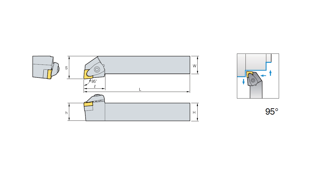
The holder angle is the main angle in the plan and it has its own cutter on each one - therefore I advise you to study the cutting tool supplier catalog in advance - it is shown there visually. In our case, you can leave 95 degrees.

The number 80 indicates the angle between the cutting edges on the tool plate. For roughing the most commonly used plate in the form of a rhombus with an angle between the faces equal to 80 degrees. In the picture you can see which plate geometries are available. It should be noted that the dumber the edge - the higher the tool's durability (i.e. it will last longer). However, dumber - does not mean that the tool will not cut the workpiece material. Edges with rounding radius from 0.8 and above, as well as, for example, round plates are called dull. This tool is used for roughing, and in turn, a tool with a sharp edge - for finishing. The difference in these treatments is the load on the plate. With roughing, you can take more material at a time (pass), but with finishing, much less with less cutting conditions.

The length of the plate, established at our size of 11 mm, is equal to the length of the cutting edge. You can directly measure the plate itself or also see the catalog.
The arrow clockwise or counterclockwise corresponds to the cutting direction. It depends on the type of holder installed and has only two values - left or right. In our case, the set arrow counterclockwise corresponds to the left rotation of the spindle, and clockwise corresponds to its right rotation. Here it is worth looking at what kind of holder is installed for processing - if at the end of the ISO symbol designation there is an R letter - then this holder is right, and if L - then the holder is left. The direction of rotation will depend, but there is one golden rule: “the direction of rotation of the workpiece must always be on the edge of the plate”
Two faucets and tick boxes are responsible for turning on cooling when cutting with our tool. As a rule, the first tick is responsible for the flow of fluid outside (irrigation), and the second - through the tool. However, this moment is better to check with the manufacturer of the machine.
Well that's all! We have successfully created the first cutting tool, with which we will process our part in the subsequent lessons.
Subscribe to the channel and put likes.
Good knowledge to you! We are waiting for your suggestions and criticism!
This is a project of Open Technical Education "Polytech 2.0".
Here is our history and ideology .
Well, after a short pause, we continued to upload the video on the CNC and here is another introductory shot.
Immediately, please unsubscribe in the comments - is it worth duplicating text training material on Habré, or better to unsubscribe new and events of the development stages of our project. We just have materials on CAD / CAM systems in the blanks that are not worthy of a separate video, but might be interesting for you!
In this video, I would like to talk about how to create a cutting tool needed for programming turning in the Siemens Sinumerik 840D Sl CNC system .:
')
This article will somewhat complement the video itself and its content, so if you have any questions, you are welcome to roll.
So! You have already seen how the CNC window and its main function keys are arranged, and now let's move on to the process of creating a tool.
When you press the Offset button, the window of the cutting tool manager installed on your machine opens. In my case, it is a lathe emulator with a 12-position turret, in which the cutting tool is installed. An example of such a head is shown in the figure:
The tool itself is installed in blocks, which are properly called snap. The blocks are different: from the usual to fix in them the tool holders to the drive, in which you can install a rotating tool, for example, a drill or a milling cutter. In conventional blocks under the cutters there is a groove width equal to the width of the holder (the most common dimensions: 20x20 mm and 25x25 mm). The cutter assembly itself is installed in this groove. The carbide plate is attached to the cutter, which carries out the cutting process.
The difference between the conventional blocks is that they use the turning of the machine spindle to machine them, and the tool is rigidly fixed to the block. But for the drive blocks, the tool itself rotates and the workpiece of the part can be rigidly clamped in the lathe chuck. There are cases when the tool rotates in the drive unit and at the same time the lathe chuck rotates - this happens, for example, when milling any contours. In the picture you can see the tail of the block with a gear on the end - this is the axis through which the rotation is transmitted to the cutting tool. The block in the figure is for vertical machining (the axis of rotation of the tool is perpendicular to the axis of rotation of the part), and there are also horizontal blocks where the axis of rotation of the tool and the part are parallel.
An example of using a vertical assembly drive unit is the milling of the keyway on the outer diameter of the part, and the horizontal one - to obtain a hexagon on the end of the part (as, for example, a bolt).
So, we will create the simplest tool - the turning tool, which we will use when machining the end face of the part and turning its outer diameter. To do this, go to the Offset window in case you were in some other window, press the “ List of Tools ” key and go to the bottom of the list (after the numbered lines). When you select the empty line at the bottom of the list, the “ New tool ” button becomes active in the right column of function keys.
A tool type selection window will open. As you can see on the CNC lathe you can install a lot of different cutting tools. For the concept of principle and algorithm of action, it is enough for us to create a rough turning tool. We select " Rough Instrument " and we have highlighted one of the four squares with the display of the position of the cutting edge. What is the difference between these four pictures?
CNC lathes come with one or two lathe spindles. For machining a part in each of the spindles, its own kind of tool position is used. If you visually look at the machine, the left spindle is usually the main or the first, and the right spindle is optional or the second.
The detail that we will process throughout the course will be set to the first spindle, and accordingly the tool position will be described by the first and third square. I won't describe the difference between them yet - because Now we will create a tool with the first kind of position, and in the next lessons we will create a tool with the third one. In a nutshell - the first view is used for external processing:
and the second for internal:
After selecting the desired position, click on the OK button. The TNC will ask us for the appropriate tool name. You can enter there any word so that you understand what kind of tool you have created, but if you work behind the machine not only you, then you should use a description of the tool created that is understandable to another person. In our case, it will be: O_ROUGH_80_08 .
This is what it means:
O - Outside (outer treatment)
ROUGH - roughing (roughing)
80 - the angle between the edges of the plate
08 - plate radius of 0.8 mm
Our tool has been successfully created; now it needs to be described with a set of relevant parameters. The length X is the position of the cutting edge along the X coordinate, the length Z is along the Z coordinate, and the length Y is along the Y coordinate. Both of these quantities are obtained by measuring the tool on the machine.
We work in the simulator, so in our case it is enough to specify the approximate values.
The radius is the radius of the cutting edge cutting edge. For rough cutters, it usually ranges from 0.8 to 1.6. Set to 0.8.
The arrow points us to the direction of installation of the tool. It defaults to our direction of the tool set on the machine.
The holder angle is the main angle in the plan and it has its own cutter on each one - therefore I advise you to study the cutting tool supplier catalog in advance - it is shown there visually. In our case, you can leave 95 degrees.
The number 80 indicates the angle between the cutting edges on the tool plate. For roughing the most commonly used plate in the form of a rhombus with an angle between the faces equal to 80 degrees. In the picture you can see which plate geometries are available. It should be noted that the dumber the edge - the higher the tool's durability (i.e. it will last longer). However, dumber - does not mean that the tool will not cut the workpiece material. Edges with rounding radius from 0.8 and above, as well as, for example, round plates are called dull. This tool is used for roughing, and in turn, a tool with a sharp edge - for finishing. The difference in these treatments is the load on the plate. With roughing, you can take more material at a time (pass), but with finishing, much less with less cutting conditions.
The length of the plate, established at our size of 11 mm, is equal to the length of the cutting edge. You can directly measure the plate itself or also see the catalog.
The arrow clockwise or counterclockwise corresponds to the cutting direction. It depends on the type of holder installed and has only two values - left or right. In our case, the set arrow counterclockwise corresponds to the left rotation of the spindle, and clockwise corresponds to its right rotation. Here it is worth looking at what kind of holder is installed for processing - if at the end of the ISO symbol designation there is an R letter - then this holder is right, and if L - then the holder is left. The direction of rotation will depend, but there is one golden rule: “the direction of rotation of the workpiece must always be on the edge of the plate”
Two faucets and tick boxes are responsible for turning on cooling when cutting with our tool. As a rule, the first tick is responsible for the flow of fluid outside (irrigation), and the second - through the tool. However, this moment is better to check with the manufacturer of the machine.
Well that's all! We have successfully created the first cutting tool, with which we will process our part in the subsequent lessons.
Subscribe to the channel and put likes.
Good knowledge to you! We are waiting for your suggestions and criticism!
Source: https://habr.com/ru/post/244937/
All Articles