Mikrotik. Failover. Load balancing
When I got the need to figure out how to do failover or load balancing, having two or more channels to the world, I found many articles and instructions that described the working configurations. But almost nowhere did he find an explanation of how everything works, and descriptions of the differences between different options. I want to correct this injustice and collect the simplest options for building failover and load balancing configurations in one article.
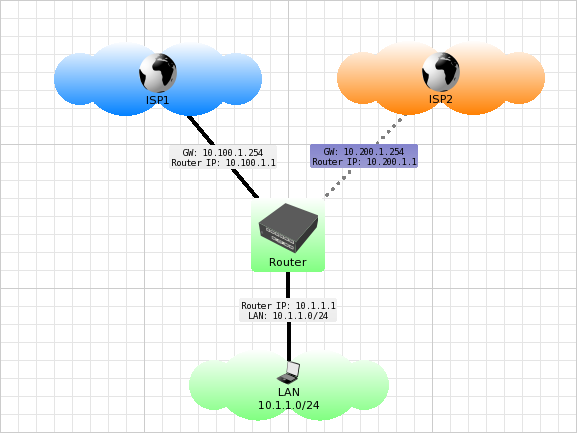
So, we have a router that connects our local network and two channels to the Internet (main ISP1 and backup ISP2).
Let's look at what we can do:
')
Immediately I will warn you: despite the fact that in this article I will describe everything for mikrotik, I will not touch on the topic of scripts
We have a backup channel to which traffic can be sent if the main one fails. But how to make mikrotik understand that the channel fell?
The simplest failover can be configured using the route priority (distance from mikrotik / cisco, metric to linux / windows), as well as the gateway availability check mechanism — check-gateway.
In the configuration below, all default Internet traffic goes through 10.100.1.254 (ISP1). But as soon as the address 10.100.1.254 becomes unavailable (and the route through it is inactive) - the traffic will go through 10.200.1.254 (ISP2).
In the last example, everything is fine, except for the situation when the provider's gateway is visible and pinged, but there is no Internet behind it. It would help us a lot if we could decide on the viability of the provider, pinging not the gateway itself, but something behind it.
I know two options for solving this engineering problem. The first and most common is to use scripts, but since in this article we don’t touch the scripts, we’ll dwell on the second. It implies the use of the scope parameter is not entirely correct, but it will help us to probe the provider's channel deeper than before the gateway.
The principle is simple:
Instead of the traditional default gateway = provider's gateway, we will tell the router that the default gateway is some of the always- accessible nodes (for example, 8.8.8.8 or 8.8.4.4) and it is in turn accessible through the provider's gateway.
Now let's look at what happens in a little more detail:
The trick is that the provider gateway does not know that 8.8.8.8 or 8.8.4.4 is a router and will send traffic in the usual way.
Our mikrotik believes that by default all Internet traffic needs to be sent to 8.8.8.8, which is not directly visible, but available through 10.100.1.254. And if the ping to 8.8.8.8 disappears (I remind you that our path to it is strictly indicated through the gateway from ISP1), then mikrotik will start sending all Internet traffic to 8.8.4.4, or rather to the recursively defined 10.200.1.254 (ISP2).
But a couple of times I had a situation when the Internet works through the provider's gateway, but there is no specific node or network. In such cases, the method described above does not really help, and to ensure uninterrupted operation, I had to check the availability of the node using scripts. By the way, if anyone knows the filer's solution to one external host without using scripts and dynamic routing protocols, share the recipe.
Now let's look at another scheme:

In it, the second second channel is no longer reserve, but equivalent. Why not use both channels at the same time, thus increasing throughput?
The first rule of Load Balancing is to monitor connections: to reply to an incoming connection from the same address to which it arrived. For outgoing connections - send packets only through the address with which the connection was established.
The second thing that is also important to understand is the need to separate the concepts of incoming and outgoing traffic. The fact is that for outgoing traffic the router can decide which way it will go, and incoming traffic for it as “Schrödinger traffic”. While it is not there, our mikrotik does not know which interface it will come through, and when it came, it’s already too late to change the interface.
Third , channel balancing is not a reservation. These are two separate functions.
So, with any channel balancing option, we first need to prepare for accepting incoming traffic and teach mikrotik to respond to incoming connections to the same channel from which they came. Using connection marking and subsequent marking of routes for them, we, in fact, make several routing tables, separate for each external address.
Thus, mikrotik will conduct each packet of the labeled connection according to the corresponding routing table and external addresses (10.100.1.1, 10.200.1.1) will be accessible from the outside without confusion in the channels and routes.
To distribute outgoing traffic across interfaces, we just need to hang the appropriate route mark for the connection. The difficulty is that you need to decide on which connection to hang the ISP1 tag, and on which ISP2.
There are several options for the separation of compounds into groups:
Rules balancing traffic, we can write hard:
For example, we want to configure the HTTP protocols (80 port), HTTPS (443 port), POP (110 port), SMTP (25 port) via ISP1, which are important for us, and all other traffic through the second provider:
We can divide the compounds in order. The first to the left, the second - to the right. It's simple.
PCC approaches the traffic division a bit more complicated. It divides traffic into groups based on TCP header data (src-address, dst-address, src-port, dst-port).
In my opinion, the easiest and most delicious way to separate traffic:
Mikrotik will divide traffic by gateway itself using the round-robin algorithm.
By the way, in version 6. RouterOS mikrotik broke the check-gateway in ECMP, so use the construction
/ ip route add gateway = 10.100.1.254,10.200.1.254 check-gateway = ping is possible and logical, but completely useless.
To mark non-live routes in ECMP, you need to create additional routes that use each of the gateways separately. With the included check-gateway, of course. Marking a route inactive, mikrotik does it for everyone.
Take 2 unequal channels, for example, 100 Mbps and 50 Mbps. We balance them via Nth, PCC or ECMP. What total bandwidth we get?
In fact, somewhere around 100 Mbps (the weakest channel X times).
This happens because mikrotik has no idea about the bandwidth of the channels, it does not measure it. It simply divides the traffic into relatively equal groups.
You can overcome this nuance by properly designing outbound traffic groups, taking into account the capacity of the channels.
Thanks for attention.
Good luck in setting up trouble-free routing systems.
So, we have a router that connects our local network and two channels to the Internet (main ISP1 and backup ISP2).
Let's look at what we can do:
')
Immediately I will warn you: despite the fact that in this article I will describe everything for mikrotik, I will not touch on the topic of scripts
Failover
We have a backup channel to which traffic can be sent if the main one fails. But how to make mikrotik understand that the channel fell?
The simplest reservation channels
The simplest failover can be configured using the route priority (distance from mikrotik / cisco, metric to linux / windows), as well as the gateway availability check mechanism — check-gateway.
In the configuration below, all default Internet traffic goes through 10.100.1.254 (ISP1). But as soon as the address 10.100.1.254 becomes unavailable (and the route through it is inactive) - the traffic will go through 10.200.1.254 (ISP2).
configuration: the simplest failover
# : /ip address add address=10.100.1.1/24 interface=ISP1 /ip address add address=10.200.1.1/24 interface=ISP2 # /ip address add address=10.1.1.1/24 interface=LAN # NAT /ip firewall nat add src-address=10.1.1.0/24 action=masquerade chain=srcnat ### ### # 2 default gateway /ip route add dst-address=0.0.0.0/0 gateway=10.100.1.254 distance=1 check-gateway=ping /ip route add dst-address=0.0.0.0/0 gateway=10.200.1.254 distance=2 check-gateway=ping check-gateway = ping for mikrotik is processed as follows:
Periodically (every 10 seconds) the gateway is checked by sending an ICMP packet (ping) to it. A lost package is considered if it has not returned within 10 seconds. After two lost packets, the gateway is considered inaccessible. After receiving a response from the gateway, it becomes available and the lost packet counter is reset.
Provide failover with deeper channel analysis
In the last example, everything is fine, except for the situation when the provider's gateway is visible and pinged, but there is no Internet behind it. It would help us a lot if we could decide on the viability of the provider, pinging not the gateway itself, but something behind it.
I know two options for solving this engineering problem. The first and most common is to use scripts, but since in this article we don’t touch the scripts, we’ll dwell on the second. It implies the use of the scope parameter is not entirely correct, but it will help us to probe the provider's channel deeper than before the gateway.
The principle is simple:
Instead of the traditional default gateway = provider's gateway, we will tell the router that the default gateway is some of the always- accessible nodes (for example, 8.8.8.8 or 8.8.4.4) and it is in turn accessible through the provider's gateway.
configuration: failover with deeper channel analysis
# : /ip address add address=10.100.1.1/24 interface=ISP1 /ip address add address=10.200.1.1/24 interface=ISP2 # /ip address add address=10.1.1.1/24 interface=LAN # NAT /ip firewall nat add src-address=10.1.1.0/24 action=masquerade chain=srcnat ### failover c ### # scope 8.8.8.8 8.8.4.4 /ip route add dst-address=8.8.8.8 gateway=10.100.1.254 scope=10 /ip route add dst-address=8.8.4.4 gateway=10.200.1.254 scope=10 # 2 default gateway /ip route add dst-address=0.0.0.0/0 gateway=8.8.8.8 distance=1 check-gateway=ping /ip route add dst-address=0.0.0.0/0 gateway=8.8.4.4 distance=2 check-gateway=ping Now let's look at what happens in a little more detail:
The trick is that the provider gateway does not know that 8.8.8.8 or 8.8.4.4 is a router and will send traffic in the usual way.
Our mikrotik believes that by default all Internet traffic needs to be sent to 8.8.8.8, which is not directly visible, but available through 10.100.1.254. And if the ping to 8.8.8.8 disappears (I remind you that our path to it is strictly indicated through the gateway from ISP1), then mikrotik will start sending all Internet traffic to 8.8.4.4, or rather to the recursively defined 10.200.1.254 (ISP2).
But a couple of times I had a situation when the Internet works through the provider's gateway, but there is no specific node or network. In such cases, the method described above does not really help, and to ensure uninterrupted operation, I had to check the availability of the node using scripts. By the way, if anyone knows the filer's solution to one external host without using scripts and dynamic routing protocols, share the recipe.
Load balancing
Now let's look at another scheme:
In it, the second second channel is no longer reserve, but equivalent. Why not use both channels at the same time, thus increasing throughput?
We start to customize load balancing
The first rule of Load Balancing is to monitor connections: to reply to an incoming connection from the same address to which it arrived. For outgoing connections - send packets only through the address with which the connection was established.
The second thing that is also important to understand is the need to separate the concepts of incoming and outgoing traffic. The fact is that for outgoing traffic the router can decide which way it will go, and incoming traffic for it as “Schrödinger traffic”. While it is not there, our mikrotik does not know which interface it will come through, and when it came, it’s already too late to change the interface.
Third , channel balancing is not a reservation. These are two separate functions.
By the way, why do we deal with connections and not packets when dividing traffic?
Read how the TCP protocol works. In short, the task of the TCP protocol is not only to throw a packet at the receiver, but also to control how it received it. This is done using the connection setup, within which, in fact, the data packets are transmitted - along with the service information. If you operate with packets and forget about connections, then there are situations when a remote host, after establishing a connection with one address, simply discards some of the packets that came from the second, the “wrong” address.
Getting ready to accept "Schrödinger traffic"
So, with any channel balancing option, we first need to prepare for accepting incoming traffic and teach mikrotik to respond to incoming connections to the same channel from which they came. Using connection marking and subsequent marking of routes for them, we, in fact, make several routing tables, separate for each external address.
initial configuration for load balancing with two external IP addresses
# : /ip address add address=10.100.1.1/24 interface=ISP1 /ip address add address=10.200.1.1/24 interface=ISP2 # /ip address add address=10.1.1.1/24 interface=LAN # NAT /ip firewall nat add src-address=10.1.1.0/24 action=masquerade chain=srcnat # : /ip firewall mangle add action=mark-connection chain=input in-interface=ISP1 new-connection-mark=cin_ISP1 /ip firewall mangle add action=mark-connection chain=input in-interface=ISP2 new-connection-mark=cin_ISP2 # , , - . /ip firewall mangle add action=mark-routing chain=output connection-mark=cin_ISP1 new-routing-mark=rout_ISP1 passthrough=no /ip firewall mangle add action=mark-routing chain=output connection-mark=cin_ISP2 new-routing-mark=rout_ISP2 passthrough=no # default gateway : /ip route add distance=1 gateway=10.100.1.254 routing-mark=rout_ISP1 check-gateway=ping /ip route add distance=1 gateway=10.200.1.254 routing-mark=rout_ISP2 check-gateway=ping Thus, mikrotik will conduct each packet of the labeled connection according to the corresponding routing table and external addresses (10.100.1.1, 10.200.1.1) will be accessible from the outside without confusion in the channels and routes.
We divide the outgoing traffic
To distribute outgoing traffic across interfaces, we just need to hang the appropriate route mark for the connection. The difficulty is that you need to decide on which connection to hang the ISP1 tag, and on which ISP2.
There are several options for the separation of compounds into groups:
1) We divide outgoing traffic, screwing the brand tightly
Rules balancing traffic, we can write hard:
For example, we want to configure the HTTP protocols (80 port), HTTPS (443 port), POP (110 port), SMTP (25 port) via ISP1, which are important for us, and all other traffic through the second provider:
channel balanced configuration according to strict rules
# : /ip address add address=10.100.1.1/24 interface=ISP1 /ip address add address=10.200.1.1/24 interface=ISP2 # /ip add address=10.1.1.1/24 interface=LAN # NAT /ip firewall nat add src-address=10.1.1.0/24 action=masquerade chain=srcnat # : /ip firewall mangle add action=mark-connection chain=input in-interface=ISP1 new-connection-mark=cin_ISP1 /ip firewall mangle add action=mark-connection chain=input in-interface=ISP2 new-connection-mark=cin_ISP2 # , , - . /ip firewall mangle add action=mark-routing chain=output connection-mark=cin_ISP1 new-routing-mark=rout_ISP1 passthrough=no /ip firewall mangle add action=mark-routing chain=output connection-mark=cin_ISP2 new-routing-mark=rout_ISP2 passthrough=no # default gateway : /ip route add distance=1 gateway=10.100.1.254 routing-mark=rout_ISP1 check-gateway=ping /ip route add distance=1 gateway=10.200.1.254 routing-mark=rout_ISP2 check-gateway=ping #failover /ip route add distance=2 gateway=10.200.1.254 routing-mark=rout_ISP1 /ip route add distance=2 gateway=10.100.1.254 routing-mark=rout_ISP2 # 80,443,110,25 ISP1 /ip firewall mangle add chain=prerouting action=mark-routing new-routing-mark="lan_out_ISP1" passthrough=no dst-port=80,443,110,25 protocol=tcp # ISP2: /ip firewall add chain=prerouting action=mark-routing new-routing-mark="lan_out_ISP2" passthrough=no # default gateway LAN : /ip route add distance=1 gateway=10.100.1.254 routing-mark=lan_out_ISP1 check-gateway=ping /ip route add distance=1 gateway=10.200.1.254 routing-mark=lan_out_ISP2 check-gateway=ping #failover /ip route add distance=2 gateway=10.200.1.254 routing-mark=lan_out_ISP1 /ip route add distance=2 gateway=10.100.1.254 routing-mark=lan_out_ISP2 2) We divide outgoing traffic, choosing every Nth connection
We can divide the compounds in order. The first to the left, the second - to the right. It's simple.
configuration with channel balancing on the N-th connection:
# : /ip address add address=10.100.1.1/24 interface=ISP1 /ip address add address=10.200.1.1/24 interface=ISP2 # /ip address add address=10.1.1.1/24 interface=LAN # NAT /ip firewall nat add src-address=10.1.1.0/24 action=masquerade chain=srcnat # : /ip firewall mangle add action=mark-connection chain=input in-interface=ISP1 new-connection-mark=cin_ISP1 /ip firewall mangle add action=mark-connection chain=input in-interface=ISP2 new-connection-mark=cin_ISP2 # , , - . /ip firewall mangle add action=mark-routing chain=output connection-mark=cin_ISP1 new-routing-mark=rout_ISP1 passthrough=no /ip firewall mangle add action=mark-routing chain=output connection-mark=cin_ISP2 new-routing-mark=rout_ISP2 passthrough=no # default gateway : /ip route add distance=1 gateway=10.100.1.254 routing-mark=rout_ISP1 check-gateway=ping /ip route add distance=1 gateway=10.200.1.254 routing-mark=rout_ISP2 check-gateway=ping # ISP1 /ip firewall mangle add src-address=10.1.1.0/24 action=mark-routing chain=prerouting new-routing-mark=lan_out_ISP1 nth=2,1 # ISP2 /ip firewall mangle add src-address=10.1.1.0/24 action=mark-routing chain=prerouting new-routing-mark=lan_out_ISP2 nth=2,2 # default gateway LAN : /ip route add distance=1 gateway=10.100.1.254 routing-mark=lan_out_ISP1 check-gateway=ping /ip route add distance=1 gateway=10.200.1.254 routing-mark=lan_out_ISP2 check-gateway=ping #failover /ip route add distance=2 gateway=10.200.1.254 routing-mark=lan_out_ISP1 /ip route add distance=2 gateway=10.100.1.254 routing-mark=lan_out_ISP2 3) We divide outgoing traffic using PCC (per connection classifier)
PCC approaches the traffic division a bit more complicated. It divides traffic into groups based on TCP header data (src-address, dst-address, src-port, dst-port).
PPC channel balanced configuration:
# : /ip address add address=10.100.1.1/24 interface=ISP1 /ip address add address=10.200.1.1/24 interface=ISP2 # /ip address add address=10.1.1.1/24 interface=LAN # NAT /ip firewall nat add src-address=10.1.1.0/24 action=masquerade chain=srcnat # : /ip firewall mangle add action=mark-connection chain=input in-interface=ISP1 new-connection-mark=cin_ISP1 /ip firewall mangle add action=mark-connection chain=input in-interface=ISP2 new-connection-mark=cin_ISP2 # , , - . /ip firewall mangle add action=mark-routing chain=output connection-mark=cin_ISP1 new-routing-mark=rout_ISP1 passthrough=no /ip firewall mangle add action=mark-routing chain=output connection-mark=cin_ISP2 new-routing-mark=rout_ISP2 passthrough=no # default gateway : /ip route add distance=1 gateway=10.100.1.254 routing-mark=rout_ISP1 check-gateway=ping /ip route add distance=1 gateway=10.200.1.254 routing-mark=rout_ISP2 check-gateway=ping #failover /ip route add distance=2 gateway=10.200.1.254 routing-mark=rout_ISP1 /ip route add distance=2 gateway=10.100.1.254 routing-mark=rout_ISP2 # PPC . /ip firewall mangle add src-address=10.1.1.0/24 action=mark-routing chain=prerouting new-routing-mark=lan_out_ISP1 per-connection-classifier=src-address-and-port:2/0 /ip firewall mangle add src-address=10.1.1.0/24 action=mark-routing chain=prerouting new-routing-mark=lan_out_ISP2 per-connection-classifier=src-address-and-port:2/1 # default gateway LAN : /ip route add distance=1 gateway=10.100.1.254 routing-mark=lan_out_ISP1 check-gateway=ping /ip route add distance=1 gateway=10.200.1.254 routing-mark=lan_out_ISP2 check-gateway=ping #failover /ip route add distance=2 gateway=10.200.1.254 routing-mark=lan_out_ISP1 /ip route add distance=2 gateway=10.100.1.254 routing-mark=lan_out_ISP2 We divide outbound traffic using ECMP (equal cost multipath routing)
In my opinion, the easiest and most delicious way to separate traffic:
channel balanced configuration via ECMP
# : /ip address add address=10.100.1.1/24 interface=ISP1 /ip address add address=10.200.1.1/24 interface=ISP2 # /ip address add address=10.1.1.1/24 interface=LAN # NAT /ip firewall nat add src-address=10.1.1.0/24 action=masquerade chain=srcnat # : /ip firewall mangle add action=mark-connection chain=input in-interface=ISP1 new-connection-mark=cin_ISP1 /ip firewall mangle add action=mark-connection chain=input in-interface=ISP2 new-connection-mark=cin_ISP2 # , , - . /ip firewall mangle add action=mark-routing chain=output connection-mark=cin_ISP1 new-routing-mark=rout_ISP1 passthrough=no /ip firewall mangle add action=mark-routing chain=output connection-mark=cin_ISP2 new-routing-mark=rout_ISP2 passthrough=no # default gateway : /ip route add distance=1 gateway=10.100.1.254 routing-mark=rout_ISP1 check-gateway=ping /ip route add distance=1 gateway=10.200.1.254 routing-mark=rout_ISP2 check-gateway=ping # /ip firewall mangle add src-address=10.1.1.0/24 action=mark-routing chain=prerouting new-routing-mark=mixed # ECMP /ip route add dst-address=0.0.0.0/0 gateway=10.100.1.254,10.200.1.254 routing-mark=mixed Mikrotik will divide traffic by gateway itself using the round-robin algorithm.
By the way, in version 6. RouterOS mikrotik broke the check-gateway in ECMP, so use the construction
/ ip route add gateway = 10.100.1.254,10.200.1.254 check-gateway = ping is possible and logical, but completely useless.
To mark non-live routes in ECMP, you need to create additional routes that use each of the gateways separately. With the included check-gateway, of course. Marking a route inactive, mikrotik does it for everyone.
And the last important note about the speed of the channels.
Take 2 unequal channels, for example, 100 Mbps and 50 Mbps. We balance them via Nth, PCC or ECMP. What total bandwidth we get?
In fact, somewhere around 100 Mbps (the weakest channel X times).
This happens because mikrotik has no idea about the bandwidth of the channels, it does not measure it. It simply divides the traffic into relatively equal groups.
You can overcome this nuance by properly designing outbound traffic groups, taking into account the capacity of the channels.
for example
in ECMP, this can be done by specifying a faster gateway several times, thereby increasing the frequency of its use.
In the PCC, unequal groups can also be made:
/ip route add dst-address=0.0.0.0/0 gateway=10.100.1.254,10.100.1.254,10.200.1.254 In the PCC, unequal groups can also be made:
/ip firewall mangle add src-address=10.1.1.0/24 action=mark-routing chain=prerouting new-routing-mark=lan_out_ISP1 per-connection-classifier=src-address-and-port:3/0 /ip firewall mangle add src-address=10.1.1.0/24 action=mark-routing chain=prerouting new-routing-mark=lan_out_ISP1 per-connection-classifier=src-address-and-port:3/1 /ip firewall mangle add src-address=10.1.1.0/24 action=mark-routing chain=prerouting new-routing-mark=lan_out_ISP2 per-connection-classifier=src-address-and-port:3/2 Thanks for attention.
Good luck in setting up trouble-free routing systems.
Source: https://habr.com/ru/post/244385/
All Articles