HP 9830B Recovery
We continue to revive the old iron. After the PDP-11, proceed to the "calculator" HP 9830B. Many heavy pictures. Italics are my comments.
In 1976, the HP 9830B was introduced, an updated version (more memory) of the HP9830A, released in 1972. The price of the calculator itself was $ 8350. An additional printer module, located on top, sold for another $ 3,350.
For the entire HP98x0 model range, the same type of 16-bit processor was used, implemented on discrete TTL logic, which was located mostly on four boards. To simplify the design, the ALU was made consistent.
')
The article describes the history of turning a device from a dusty box with broken buttons into a fully working calculator.

Our copy was previously used in accounting and came to us with two large drives on cartridges similar to HP7900 and DEC RK05 ( I think this is HP 9880, which supported 2 cartridges with a diameter of 36cm - one as permanent storage, the second as removable ). Accounting past is confirmed by stickers for the keyboard and inscriptions on the cartridges.
The calculator spent some time in a dusty warehouse, but the first obvious problem was with the keys - four of them were broken, and three, from the top row, were not at all. "DELETE LINE", "END" and the number 5.
I was able to purchase a set of keys for the keyboard of the HP264x terminal, but among them there were no “DELETE LINE” and “END”. But good luck favored me, and DELETE LINE was sent by a collector from Holland, and END came from Canada. Thanks for this!
Returning to the problem of broken buttons, I contacted Cherry (they produce keyboards, quite good ones, by the way ), but I couldn’t get any useful information ( surprisingly, if I could, since Cherry moved to Germany in the late 70s ). They could not even recognize the keys, despite the presence of the inscription “CHERRY”.
I tried to repair them myself. I took the string wire and bent it in the shape of the letter U, then, using a soldering iron, melted it into the plastic of the button. However, a 100% match with the original could not be achieved.
It turned out half a millimeter higher, but to me it does not matter. The main thing is that the construction looks strong enough and should not break so easily. However, this stage of restoration ended with the fact that the collector from Canada was so kind that he sent five more keys for replacement. Therefore, I did not have to try out my own repair buttons.
Tony Duell designed the electrical circuit for a large number of machines from HP. That helped me a lot, as only a few original schemes from the company are available. Unlike DEC, HP never published them. I contacted Tony and got an excellent HP98x0 series calculator repair guide (this file was in PostScript format and weighed quite a bit, but I converted it to PDF, so the size has increased significantly). In addition, I downloaded the electronic circuits made by Tony. While searching for materials on the HP9830, I came across an excellent Brent page and an emulator for this calculator.
After I cleaned the unit of dust, I started with a megger meter (a special device that, oddly enough, measures large resistances ) to check the transformer insulation, following the advice from Tony's manual. No deviations. Then I slowly started the car through a continuously adjustable transformer (having removed all the boards in advance, except for the PSU module). Measuring the voltage at the outputs of the power supply gave the correct values. But it turned out that the + 5V switch needs to be supplied with a minimum load, as well as the 19.5V output circuit. About the second, I would have learned if I had studied the circuit before applying power. 19.5V is generated by the circuit of the current source, and, without a load, simply gives off an unregulated voltage. Connecting a 1 kΩ resistor and a ROM card as an artificial load gives 5.01V. 19.5V should be adjusted through the Zener diode to 16V, but, without a load on this circuit, the output 16V starts to grow. I think that, in the end, the overload protection circuit will work, but in tests with variacs ( “a continuously adjustable transformer” it takes a long time to write, so they often use tracing paper ) never before.
Since all the voltage measurements were correct, I inserted the cards back and pressed the power button. It's amazing that I got at least something!
And after pressing a random key and then “EXECUTE”, I saw the following line:
It seems to me that it would be nice to show the insides of HP9830. Therefore, I made a general view of all the boards of the calculator. They are wonderful.
All cards are gilded. Fantasy! Excellent quality.
The first and second rows are a memory subsystem with a main board containing DRAM on TMS4060 4k NMOS chips. The third row is the display and cassette controllers. The fourth row is filled with processor cards, and the last one contains the display itself and the PSU. As far as I know, the HP9830B differs from the HP9830A only in the memory card (in the second row, on the left) and in the addressing card (in the first row, on the left).
As soon as I received the keyboard covers and switches, I was able to rebuild the keyboard:
I pressed the rewind button, but from external manifestations there was only a sound of rotation, although there was no movement itself. I think that there would still have to be a clicking sound from the solenoids. If it is not there, it means that either a failure has occurred, or it has jammed them. When I opened the drive module, I found that the rubber pads on the wheels were worn out so I, at a minimum, needed to correct this defect.

New o-ring'i ( sealing ring, the same rubber on the wheels ) arrived and were installed instead of the old. Bulb for leader tape ( leader lamp, not sure if there is a Russian term. On magnetic tapes there is no working layer in the first and last Nmm, and when the film is rewound, it is illuminated with such a lamp, and when an empty area appears , the detector triggers and stops rewinding ) was damaged, and I replaced it with a white LED (yes, I know that in its place there should be a small incandescent lamp 5V 60mA, but I can argue that if the LEDs were available in 1972, then HP would use them). Now rewind earned, and the solenoids, really, just jammed.
I also tried the “MARK” command (the tape contains several files in a flat structure, the MARK XX command, YY creates XX files with a length of YY. It’s generally strange to start testing with this command because it involves a huge number of blocks of the entire computer ) but the drive continued to rotate until it stopped at some point, and the machine stopped responding to external commands.
After the reboot, I noticed that the machine is mistaken even in simple arithmetic. On 2 + 2 answers 8.4444444, but 3 + 1 gives 6.4444444. Pretty weird. This part of the calculator should work flawlessly.
Just dialing the numbers and pressing "EXECUTE", I got a strange result.
0 turned into 2, 1 in 3, 7 in 9, but 8 in 32.9444444, and 9 in 33.9444444.
18 to 20, 19 to 21, but 20 to 42, 11 to 33, 30 to 52, 1000 to 3222.
SQR (2) returned 2.22636363, and 2 ^ 2 yielded 41.96520965.
What's happening?
Despite all this, I can write a simple program on BASIC, a la:
And it will work correctly!
It looks as if the calculator adds 2 to each digit of a number, but if overflow occurs (8 + 2), then we get some strange floating point number.
The problem is definitely not in the keyboard module, because the line numbers for BASIC are entered correctly. In addition, the AUTO # button ( AUTO # XX, YY, where XX is the initial line number, and YY is the increment. Press AUTO # + 10.5 + EXECUTE to obtain the line number 10, AUTO # + EXECUTE displays 15, next time 20, then 25, and so on ) also works as it should, that is, the simplest integer arithmetic is in order.
Perhaps this behavior comes from floating point numbers? I believe that the memory subsystem works without failures, since it can store the program on BASIC and execute it.
I, nevertheless, was not completely sure whether the problem was in ROM or in RAM, until I switched the calculator to FLOAT11 mode ( floating-point numbers, 11 significant digits after the dot ) and did not enter 1,000,000. I received the number 3.22222222222 + E6, in which the exhibitor is displayed correctly, but the mantissa is incorrect in all figures. This fact, together with the addition of two to the numbers (22222 turns into 44444), turned my eyes to the ALU ROMs.
I checked the BCD ROM, but its dump is absolutely identical to what Tony provided. The funny thing is that the machine can execute BASIC programs without using this unit!
Then I followed the main ALU ROM, the first 128 nibbles ( Intel 3601, 4-bit x 256 were taken for ROM ) were considered normal, but the last 128 were simply pro-OR-en with the first part of the memory. Looking at the scheme, you can see that the upper part of the addresses is used when the BCD signal is set ( in the diagram it stands so straight, A7 is pulled up on the BCD ). Now there is a sense that BCD arithmetic does not work, although everything is fine with the usual one.
I ordered a chip from Bulgaria, and its programming was included in the price! Although, I think it would be possible to do this on my Data IO 29B programmer. I had difficulty programming some Harris chips and, moreover, I never tried to program Signetics chips on it.
82S126 arrived from Bulgaria, and Nikolay coped well with its programming. I checked the chip on Data IO, and he confirmed that everything is OK.
We solder it in the right place, and my HP9830B comes back to life again! Now he must be able to count correctly.
I can continue from the place where I stopped last time when I discovered this bug. Namely, the launch of the tape drive. Unfortunately, it does not work very well.
Entering the “MARK” command still makes it rotate for a while, then stop and the suspended system. Repeat all operations for its inclusion again.
Running other commands related to the operation of the drive, like TLIST, STORE, FIND, received in response ERROR 58, which seems to be a common error. And this message is displayed immediately, the calculator does not even try to do anything.
I am a little surprised by the fact that the “MARK” command is being executed, but it never ends. What is waiting for the car? Since REWIND works, I think EOT / BOT LDR ( I mentioned it in the light bulb remark, LDR is just a photoresistor. EOT - End of Tape, BOT - Beginning of Tape, but here these terms are incorrect. In tape format, they perform another role. Here it is more correct to talk about the leader, clear-leader ) the detector is not malfunctioning.
I thought that replacing incandescent bulbs to LED will take place without problems. But now it occurred to me that perhaps the light was too bright. This leads to erroneous operation of the photoresistor. The harsh truth came to me at the moment when the tape stopped in the middle while rewinding, and I pressed the REWIND button again (and held it). The drive was rewinding very slowly, just as slowly as on the leader tape. Then I removed the cassette and inserted it back, and it rewound normally for a while. I assume that as a result of such maneuvers the cassette took a slightly different position.
A resistor with a little more resistance solved the problem. Now the cassette was scrolled many times in a row without any stops.
But the main problem with the commands for working with magnetic tape has not been solved.
I need extension boards so that I can connect the probes of the logic analyzer. It is very annoying that there are a lot of different form factors for connectors. Six or seven types of extension boards are needed to cover all the options. After I decided to resort to a logic analyzer, I ordered the production of such boards from John Neri from the USA.
We were in contact with the Swedish Maritime Administration, because there was a computer from HP, whose fate we were asked to take in our hands. After I found out about this, the best solution was to go to Norrköping and look at it. During the inspection, I noticed the marking HP9810! I brought it home and cleaned it. He was very dusty. I slowly applied voltage through the variac and monitored the state of the power supply. He was in good shape. But, unfortunately, this was the only thing that pleased us. The computer was dead with all the cards connected, and it was not the fault of PSU, which could not withstand the full load, because all the voltage measurements gave the correct result, even with a set of cards. Checking the processor cards on a running HP9830 revealed a malfunction in the boards of the operating machine and the clock generator. The other two boards worked fine. The transfer of obviously working cards with HP9830 did not bring success. The only manifestation was to turn on the STATUS light after some time. Based on this, I decided that there are multiple faults. Therefore, I set it aside for the time being and began cleaning the HP9866 printer ( top of 9830B, separate module ), which I brought home from the warehouse.
The HP9866 was also completely dusty. I formed the capacitors. They were all in excellent condition. Therefore, I launched the power supply. No obvious problems. The LOAD button worked, and I successfully loaded the paper into the printer.
Connect it to 9830. He did not earn. Since both the printer and the tape drive depended on a single I / O processor card, I changed it to a card from the HP9810A. Well, it didn't really help the printer, but the drive was working!
I was finally able to successfully execute the “MARK” command, which consisted in stopping after a short interval, instead of scrolling to the end of the tape. I managed to tape a small program on BASIC and load it back!
I connected the analyzer probes to the HP9866 microcode address bus, which is derived as part of the test pad on the control board. I actively used the schemes drawn by Tony on the basis of his reverse engineering of this module.
To understand what was going on inside the printer, I again used Tony's help — he did an excellent job describing the micro code. I will leave it here:
Perhaps, I will leave it without translation, although it is rather amusing to read. Unless, I will give an explanation of the format. The general structure is "Status ID: opcode action_list". Each action is: 1. if (XXX) goto (YY, ZZ) - XXX is a signal, if there is a trailing slash, then it is a signal with an active-low level, switching to YY, if XXX is false, otherwise to ZZ; 2. goto (XX) - just go to XX; 3. Everything else is set to high level with the specified name.
When a command is sent from the calculator to a printer for printing, it looks like a series of strobe pulses. Each series represents one character that is processed by a microcode.
I received a sequence of states “00, 02, 06, 12, 19, 14, 0D, 11, 10, 00”, which coincides quite well with what is needed. As soon as the LF symbol is detected ( not the full sequence is given, but only its beginning, therefore in the example after state 12 goes to 1B, but 19, as it should have been at LF'e ), the state machine switches to the new path, which ends with waiting able to 13 as long as Timing is active. After the end of the wait, a jump to the state 16 follows. Starting from this moment, the looping “16, 0B, 1E, 01, 18, 0F, 1A, 07, 1C, 03” occurs, and then again 18 and to the new circle.
Immediately checked the signal newbank / ( which is involved in the condition of the transition from state 03 ), but it switches as it should on the basis of input signals. However, during the execution of micro-instructions for state 03, the input 74150 (a simple multiplexer ) is sent 8, instead of the expected 0. It seems that the signal RotEn /, which is fed to the input D4 of the multiplexer is always at a high level. Testing the RotEn signal supplied to the 7404 inverter gives us that it is always at a low level ( in fact, we simply check all the elements in the signal path in order to make sure that they do not fail ). RotEn comes from an operating machine board, which I'll be testing now.
The next step was to track the signal in the operating device to the U19 chip, but suddenly it turned out that there was no such chip on the board! Before that, I had no need to verify that the electronic circuit corresponds to this particular board. I just assumed it was. In my HP9866, there were two different modules from the module - the above-mentioned automatic machine 09866-66591 and control board 09866-66592. The reason for the differences was that I had HP9866B, and the diagrams were made for HP9866A!
The operating machine had another ROM for character encoding - SCM3632 from Motorola, with an HP ID of 1818-0167. Two quad-shift TMS3120 shift registers ( quadruple, four registers with separate legs in one case ) from Texas Instruments were used instead of three MM5052.
I decided that HP changed only the PCB layout, but the signals for the connector with the cross-board left the same. Rapid testing of the RotEn signal revealed that it comes from the sixth pin of the U8 chip, which is 1820-0071. Google told me that this is 7440. It is fully consistent with the scheme that Tony made.
Control board I can not say exactly what has changed in it. However, the microcode ROM has the same nomenclature as in the diagram, so my inventions, made earlier, must still be correct. That is, the input signals and control codes should be fed to the 74150 ones that I was thinking about.
The next step should be the measurement of signals on the U8, U3 (7490) chips and on the U13 with the number 1820-0174, behind which lies 7404.
While debugging the printer, suddenly, strobe pulses stopped coming from the calculator. I immediately tried if another I / O module was working — a tape drive. It did not work ... Let me remind you that I had previously replaced the card in 9830 with a card from 9810, since it worked better. However, it seems that now she is also failing.
Let's start debugging this board. After reading the manual from Tony and studying the diagrams, I had an idea that the ribbon usage flag was incorrectly determined, which goes through the Bus_IO_Rd / ( nCFI signal in a newer version of the scheme from Brent ). After that, it passes the three-input NAND-valve 7410, monostable multivibrator 74121, trigger 7474, and then the I / O-flag is generated at the output of the 7453 valve. Therefore, I connected the analyzer probes to these microcircuits, designated as U7, U8, U9 and U13.
By the way, pay attention to the use of extension boards. Now, if necessary, you can easily bring the probes to the contacts of the connector with the cross-board.
The HP1664 analyzer triggered a trigger for a drop in the signal from pin 9 on the U7 chip. The output signal on pin 1 of the U8 (74121) chip was quite entertaining.
It seems that this signal is always at a low level, although the non-inverted output is healthy ( pin1 = NOT pin6 for 74121, and, judging by the picture, U8 6 is fine ). Replacing with 74121 from another board (it’s very annoying that 7412X and 74123 were present in my relatively large set of 74XX chips, although 74122 and 74123 were present) gave a much better result.

Now the commands for the drive have worked exactly the same as with the replacement card from 9810 (before it broke).
Before the I / O board went out of order, I tracked the signal from RotEn, which never changed. The signal was generated by an operating machine board, which was different from the schemes I used.
Therefore, I drew my own actual version.
I connected the analyzer to U3, U7, U8, U13 and U14. Immediately after turning on the printer, I noticed that the output pin 4 to U13 (7404 inverter) was constantly switching from one level to another, while the Qd signal from 7490, which was always low, was fed to the input. This is definitely wrong behavior.
After replacing the 7404 with a new chip, the printer began to stretch the paper, line by line, and not hang on waiting, as before. It did not print anything, because I dismantled the printhead and its power supply in order to prevent any potential damage in case the logic is faulty.
I just checked the signal bank, which chooses which group of needles in the head to use (The board responsible for working with the needles was one, but it contained 4 groups of 5 needles, since the characters were set by a 5x7 matrix. To optimize the temperature and power consumption, the engineers decided to use these groups sequentially.Group 1 prints lines for characters in positions 1, 5, 9, ..., 79, group 2 - 2, 6, ... 78, etc. That is, in fact, four passes are made. This signal just sets the number of the passage. ). Everything was OK. It was embarrassing that the marking marked the location of the first pin in the opposite of where it should be, the end of the connector. However, I returned the print head to its place and tested the printer. He worked!

I made a small video with information about the calculator and its repair.
It is interesting to see the last part of the video, which shows the process of work.
I replaced the following components:
I still have a disk subsystem of two heavy drives for 14 "cartridges (plus a pallet for fixed storage), two heavy power supplies, a control module, cables and a ROM cartridge. All this is in stock, but I will leave it this is for the following years.
HP 9830B calculator with BASIC support
In 1976, the HP 9830B was introduced, an updated version (more memory) of the HP9830A, released in 1972. The price of the calculator itself was $ 8350. An additional printer module, located on top, sold for another $ 3,350.
For the entire HP98x0 model range, the same type of 16-bit processor was used, implemented on discrete TTL logic, which was located mostly on four boards. To simplify the design, the ALU was made consistent.
')
The article describes the history of turning a device from a dusty box with broken buttons into a fully working calculator.
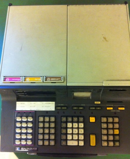
What we have
Our copy was previously used in accounting and came to us with two large drives on cartridges similar to HP7900 and DEC RK05 ( I think this is HP 9880, which supported 2 cartridges with a diameter of 36cm - one as permanent storage, the second as removable ). Accounting past is confirmed by stickers for the keyboard and inscriptions on the cartridges.
The calculator spent some time in a dusty warehouse, but the first obvious problem was with the keys - four of them were broken, and three, from the top row, were not at all. "DELETE LINE", "END" and the number 5.
I was able to purchase a set of keys for the keyboard of the HP264x terminal, but among them there were no “DELETE LINE” and “END”. But good luck favored me, and DELETE LINE was sent by a collector from Holland, and END came from Canada. Thanks for this!
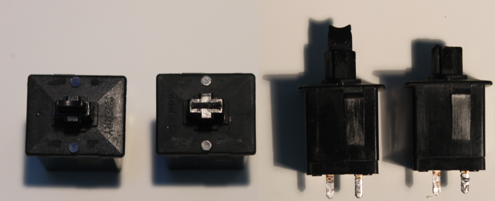
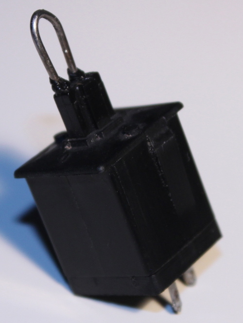
Returning to the problem of broken buttons, I contacted Cherry (they produce keyboards, quite good ones, by the way ), but I couldn’t get any useful information ( surprisingly, if I could, since Cherry moved to Germany in the late 70s ). They could not even recognize the keys, despite the presence of the inscription “CHERRY”.
I tried to repair them myself. I took the string wire and bent it in the shape of the letter U, then, using a soldering iron, melted it into the plastic of the button. However, a 100% match with the original could not be achieved.
It turned out half a millimeter higher, but to me it does not matter. The main thing is that the construction looks strong enough and should not break so easily. However, this stage of restoration ended with the fact that the collector from Canada was so kind that he sent five more keys for replacement. Therefore, I did not have to try out my own repair buttons.
Scheme
Tony Duell designed the electrical circuit for a large number of machines from HP. That helped me a lot, as only a few original schemes from the company are available. Unlike DEC, HP never published them. I contacted Tony and got an excellent HP98x0 series calculator repair guide (this file was in PostScript format and weighed quite a bit, but I converted it to PDF, so the size has increased significantly). In addition, I downloaded the electronic circuits made by Tony. While searching for materials on the HP9830, I came across an excellent Brent page and an emulator for this calculator.
Check the power supply
After I cleaned the unit of dust, I started with a megger meter (a special device that, oddly enough, measures large resistances ) to check the transformer insulation, following the advice from Tony's manual. No deviations. Then I slowly started the car through a continuously adjustable transformer (having removed all the boards in advance, except for the PSU module). Measuring the voltage at the outputs of the power supply gave the correct values. But it turned out that the + 5V switch needs to be supplied with a minimum load, as well as the 19.5V output circuit. About the second, I would have learned if I had studied the circuit before applying power. 19.5V is generated by the circuit of the current source, and, without a load, simply gives off an unregulated voltage. Connecting a 1 kΩ resistor and a ROM card as an artificial load gives 5.01V. 19.5V should be adjusted through the Zener diode to 16V, but, without a load on this circuit, the output 16V starts to grow. I think that, in the end, the overload protection circuit will work, but in tests with variacs ( “a continuously adjustable transformer” it takes a long time to write, so they often use tracing paper ) never before.
Works?
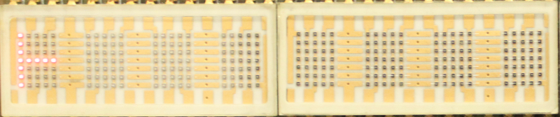
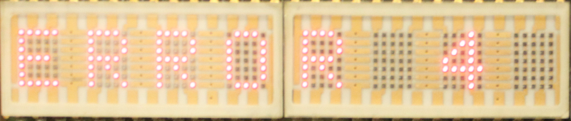
Since all the voltage measurements were correct, I inserted the cards back and pressed the power button. It's amazing that I got at least something!
And after pressing a random key and then “EXECUTE”, I saw the following line:
Quality
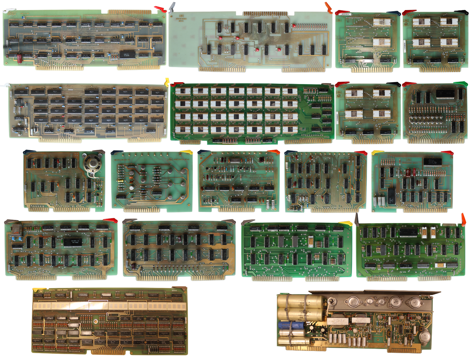
It seems to me that it would be nice to show the insides of HP9830. Therefore, I made a general view of all the boards of the calculator. They are wonderful.
All cards are gilded. Fantasy! Excellent quality.
The first and second rows are a memory subsystem with a main board containing DRAM on TMS4060 4k NMOS chips. The third row is the display and cassette controllers. The fourth row is filled with processor cards, and the last one contains the display itself and the PSU. As far as I know, the HP9830B differs from the HP9830A only in the memory card (in the second row, on the left) and in the addressing card (in the first row, on the left).
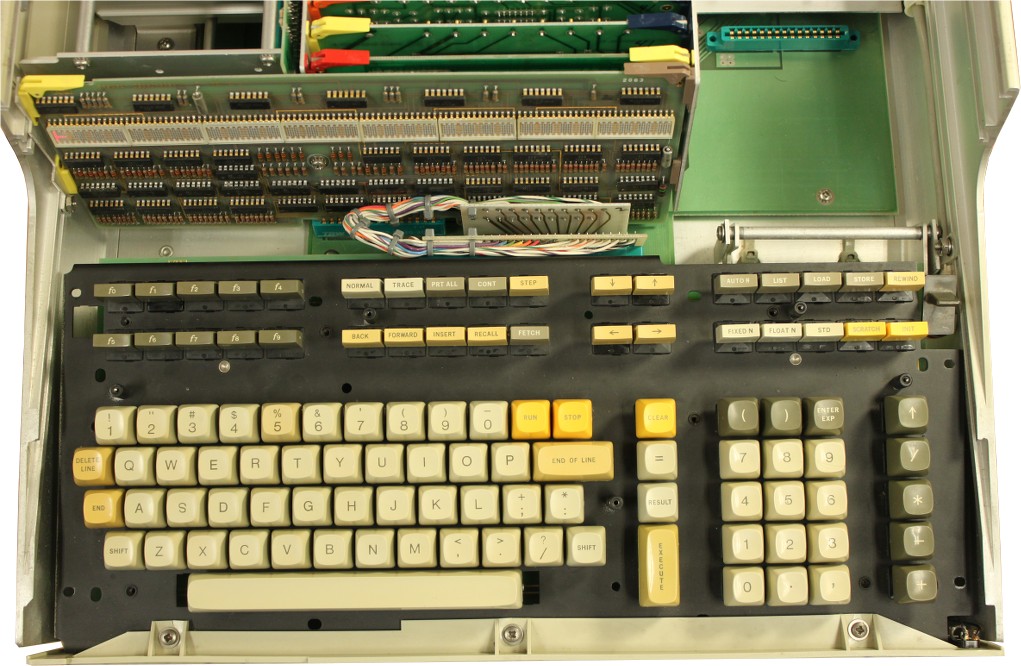
Keyboard assembly
As soon as I received the keyboard covers and switches, I was able to rebuild the keyboard:
Magnetic tape drive
I pressed the rewind button, but from external manifestations there was only a sound of rotation, although there was no movement itself. I think that there would still have to be a clicking sound from the solenoids. If it is not there, it means that either a failure has occurred, or it has jammed them. When I opened the drive module, I found that the rubber pads on the wheels were worn out so I, at a minimum, needed to correct this defect.
New challenges
New o-ring'i ( sealing ring, the same rubber on the wheels ) arrived and were installed instead of the old. Bulb for leader tape ( leader lamp, not sure if there is a Russian term. On magnetic tapes there is no working layer in the first and last Nmm, and when the film is rewound, it is illuminated with such a lamp, and when an empty area appears , the detector triggers and stops rewinding ) was damaged, and I replaced it with a white LED (yes, I know that in its place there should be a small incandescent lamp 5V 60mA, but I can argue that if the LEDs were available in 1972, then HP would use them). Now rewind earned, and the solenoids, really, just jammed.
I also tried the “MARK” command (the tape contains several files in a flat structure, the MARK XX command, YY creates XX files with a length of YY. It’s generally strange to start testing with this command because it involves a huge number of blocks of the entire computer ) but the drive continued to rotate until it stopped at some point, and the machine stopped responding to external commands.
After the reboot, I noticed that the machine is mistaken even in simple arithmetic. On 2 + 2 answers 8.4444444, but 3 + 1 gives 6.4444444. Pretty weird. This part of the calculator should work flawlessly.
Just dialing the numbers and pressing "EXECUTE", I got a strange result.
0 turned into 2, 1 in 3, 7 in 9, but 8 in 32.9444444, and 9 in 33.9444444.
18 to 20, 19 to 21, but 20 to 42, 11 to 33, 30 to 52, 1000 to 3222.
SQR (2) returned 2.22636363, and 2 ^ 2 yielded 41.96520965.
What's happening?
Despite all this, I can write a simple program on BASIC, a la:
10 DISP "HELLO WORLD" 20 GOTO 10 And it will work correctly!
It looks as if the calculator adds 2 to each digit of a number, but if overflow occurs (8 + 2), then we get some strange floating point number.
The problem is definitely not in the keyboard module, because the line numbers for BASIC are entered correctly. In addition, the AUTO # button ( AUTO # XX, YY, where XX is the initial line number, and YY is the increment. Press AUTO # + 10.5 + EXECUTE to obtain the line number 10, AUTO # + EXECUTE displays 15, next time 20, then 25, and so on ) also works as it should, that is, the simplest integer arithmetic is in order.
Perhaps this behavior comes from floating point numbers? I believe that the memory subsystem works without failures, since it can store the program on BASIC and execute it.
I, nevertheless, was not completely sure whether the problem was in ROM or in RAM, until I switched the calculator to FLOAT11 mode ( floating-point numbers, 11 significant digits after the dot ) and did not enter 1,000,000. I received the number 3.22222222222 + E6, in which the exhibitor is displayed correctly, but the mantissa is incorrect in all figures. This fact, together with the addition of two to the numbers (22222 turns into 44444), turned my eyes to the ALU ROMs.
I checked the BCD ROM, but its dump is absolutely identical to what Tony provided. The funny thing is that the machine can execute BASIC programs without using this unit!
Then I followed the main ALU ROM, the first 128 nibbles ( Intel 3601, 4-bit x 256 were taken for ROM ) were considered normal, but the last 128 were simply pro-OR-en with the first part of the memory. Looking at the scheme, you can see that the upper part of the addresses is used when the BCD signal is set ( in the diagram it stands so straight, A7 is pulled up on the BCD ). Now there is a sense that BCD arithmetic does not work, although everything is fine with the usual one.
I ordered a chip from Bulgaria, and its programming was included in the price! Although, I think it would be possible to do this on my Data IO 29B programmer. I had difficulty programming some Harris chips and, moreover, I never tried to program Signetics chips on it.
Run again
82S126 arrived from Bulgaria, and Nikolay coped well with its programming. I checked the chip on Data IO, and he confirmed that everything is OK.
We solder it in the right place, and my HP9830B comes back to life again! Now he must be able to count correctly.
I can continue from the place where I stopped last time when I discovered this bug. Namely, the launch of the tape drive. Unfortunately, it does not work very well.
Entering the “MARK” command still makes it rotate for a while, then stop and the suspended system. Repeat all operations for its inclusion again.
Running other commands related to the operation of the drive, like TLIST, STORE, FIND, received in response ERROR 58, which seems to be a common error. And this message is displayed immediately, the calculator does not even try to do anything.
I am a little surprised by the fact that the “MARK” command is being executed, but it never ends. What is waiting for the car? Since REWIND works, I think EOT / BOT LDR ( I mentioned it in the light bulb remark, LDR is just a photoresistor. EOT - End of Tape, BOT - Beginning of Tape, but here these terms are incorrect. In tape format, they perform another role. Here it is more correct to talk about the leader, clear-leader ) the detector is not malfunctioning.
BOT sensor
I thought that replacing incandescent bulbs to LED will take place without problems. But now it occurred to me that perhaps the light was too bright. This leads to erroneous operation of the photoresistor. The harsh truth came to me at the moment when the tape stopped in the middle while rewinding, and I pressed the REWIND button again (and held it). The drive was rewinding very slowly, just as slowly as on the leader tape. Then I removed the cassette and inserted it back, and it rewound normally for a while. I assume that as a result of such maneuvers the cassette took a slightly different position.
A resistor with a little more resistance solved the problem. Now the cassette was scrolled many times in a row without any stops.
But the main problem with the commands for working with magnetic tape has not been solved.
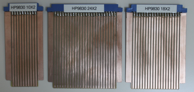
I need extension boards so that I can connect the probes of the logic analyzer. It is very annoying that there are a lot of different form factors for connectors. Six or seven types of extension boards are needed to cover all the options. After I decided to resort to a logic analyzer, I ordered the production of such boards from John Neri from the USA.
HP9810
We were in contact with the Swedish Maritime Administration, because there was a computer from HP, whose fate we were asked to take in our hands. After I found out about this, the best solution was to go to Norrköping and look at it. During the inspection, I noticed the marking HP9810! I brought it home and cleaned it. He was very dusty. I slowly applied voltage through the variac and monitored the state of the power supply. He was in good shape. But, unfortunately, this was the only thing that pleased us. The computer was dead with all the cards connected, and it was not the fault of PSU, which could not withstand the full load, because all the voltage measurements gave the correct result, even with a set of cards. Checking the processor cards on a running HP9830 revealed a malfunction in the boards of the operating machine and the clock generator. The other two boards worked fine. The transfer of obviously working cards with HP9830 did not bring success. The only manifestation was to turn on the STATUS light after some time. Based on this, I decided that there are multiple faults. Therefore, I set it aside for the time being and began cleaning the HP9866 printer ( top of 9830B, separate module ), which I brought home from the warehouse.
The tape drive is working!
The HP9866 was also completely dusty. I formed the capacitors. They were all in excellent condition. Therefore, I launched the power supply. No obvious problems. The LOAD button worked, and I successfully loaded the paper into the printer.
Connect it to 9830. He did not earn. Since both the printer and the tape drive depended on a single I / O processor card, I changed it to a card from the HP9810A. Well, it didn't really help the printer, but the drive was working!
I was finally able to successfully execute the “MARK” command, which consisted in stopping after a short interval, instead of scrolling to the end of the tape. I managed to tape a small program on BASIC and load it back!
We debug the printer
I connected the analyzer probes to the HP9866 microcode address bus, which is derived as part of the test pad on the control board. I actively used the schemes drawn by Tony on the basis of his reverse engineering of this module.
To understand what was going on inside the printer, I again used Tony's help — he did an excellent job describing the micro code. I will leave it here:
Hidden text
HP9866 Control State Machine ---------------------------- ** Character Entry ** 00 : 20 if(Stb/) goto (00,02) , ClrFlg Start of main loop (also entry point on power on). Clear interface flag (not busy) Wait for strobe pulse on interface 02 : 2B goto (06) 06 : C2 if(PrtChar) goto (12,11) , InClk Load chracter into input register, set interface flag flip-flop (indicating printer busy). Test if it is a printable character (including linefeed). If not, ignore it. 12 : F4 if(LF/) goto (19,1B) Is it a linefeed? 1B : CF if(Empty/) goto (17,15) Input character is a linefeed. Is the line buffer empty? If so, just feed the paper, if not, do a full print cycle. 19 : C1 if(Start/) goto (14,11) It's not a linefeed. Is the line buffer full (that is character counter = 0 and empty/ flip-flop set). If so, ignore it (truncate the line) 14 : 9D goto (0D) , SClk Line buffer is not full, store new character in the shift register 0D : C4 goto (11) , PHOut Increment the character counter, set empty/ flip-flop, and end this character 11 : C0 if(Stb/) goto (10,11) End of character processing. Loop until strobe is inactive 10 : 00 goto (00) , ClrFlg Clear interface flag and round again. ** Print cycle ** Now to actually print a line. Begin by filling the unused space in the data shift register with spaces 17 : 89 if(Start/) goto (04,05) , ForceSpace Set the data input flip-flops to a space character. Exit from loop when the line buffer is full (effectively a while(buffer not full) loop). 04 : 10 goto (08) , SClk Load a space into the next buffer location 08 : EF goto (17) , PHClk Increment character counter and round again. The line buffer is now ready, so print it. 05 : E6 goto (13) , Autofeed Advance the paper one dot line 13 : E3 if(Timing) goto (16,13) Loop until U26b times out to give the motor time to move 16 : 3E if(Row7) goto (0B,0E) , InClk Is this the end of the printed character (7 rows of dots printed)? If so, goto the paper feed routine, starting by incrementing the row counter. 0B : 7B goto (1E) 1E : 84 goto (01) , RowClk Increment row counter. This also controls the RotEn line so as to go into printing mode 01 : 50 goto (18) 18 : BF goto (0F) , PHClk Clock the 5 bits for the current row of the current character into the printhead shift registers. 0F : DA if(char0/) goto (1A,1D) Is the line completed? This will skip the 4-chracter rotation at the end of the complete print line, so as to leave the line buffer in the same state at the start and end of a line. Thus each row of dots comes from the same chracters in the same positions. 1A : AF goto (07) 07 : 59 goto (1C) , ForceSpace No, start to roate the line buffer by 4 characters. Now ForceSpace/ had a second meaning. It increments the '4 character' counter U17a/b 1C : A7 if(LnFlg) goto (07,03) , SClk Rotate the line buffer and round again if it's not been done 4 times (print every 4th character on each pass) 03 : D8 if(newbank/) goto (18,1D) Has a complete bank been loaded? If not, go back and load the next character. 1D : 32 goto (0A) , PHOut A complete bank has been loaded, so trigger printhead timing monostable and print this bank of dots. 0A : 31 if(Timing) goto (0C,0A) Wait for U26a to time out (this bank has been printed). 0C : 8C if(firstbank/) goto (01,05) , SClk Rotate the line buffer by one character to get the next quarter of a line into postion. Has the character counter wrapped around so all banks have been done? If so, back round, advance the paper and start the next dot line. If not, then round again to start the next bank of data ** Paper feed ** This routine advances the paper by enough dot lines to complete the character and inter-row space 15 : 94 goto (09) , Autofeed Clock the stepper motor counter 09 : 93 if(Timing) goto (0E,09) Loop until monostable U26b times out (to give motor time to move) 0E : FF goto (1F) , RowClk Increment dot row counter 1F : C5 if(RotEn) goto (15,11) Round again if dot row counter has not got back to 0 (RotEn = 1). Otherwise go to end of character processing Perhaps, I will leave it without translation, although it is rather amusing to read. Unless, I will give an explanation of the format. The general structure is "Status ID: opcode action_list". Each action is: 1. if (XXX) goto (YY, ZZ) - XXX is a signal, if there is a trailing slash, then it is a signal with an active-low level, switching to YY, if XXX is false, otherwise to ZZ; 2. goto (XX) - just go to XX; 3. Everything else is set to high level with the specified name.
When a command is sent from the calculator to a printer for printing, it looks like a series of strobe pulses. Each series represents one character that is processed by a microcode.
I received a sequence of states “00, 02, 06, 12, 19, 14, 0D, 11, 10, 00”, which coincides quite well with what is needed. As soon as the LF symbol is detected ( not the full sequence is given, but only its beginning, therefore in the example after state 12 goes to 1B, but 19, as it should have been at LF'e ), the state machine switches to the new path, which ends with waiting able to 13 as long as Timing is active. After the end of the wait, a jump to the state 16 follows. Starting from this moment, the looping “16, 0B, 1E, 01, 18, 0F, 1A, 07, 1C, 03” occurs, and then again 18 and to the new circle.
Immediately checked the signal newbank / ( which is involved in the condition of the transition from state 03 ), but it switches as it should on the basis of input signals. However, during the execution of micro-instructions for state 03, the input 74150 (a simple multiplexer ) is sent 8, instead of the expected 0. It seems that the signal RotEn /, which is fed to the input D4 of the multiplexer is always at a high level. Testing the RotEn signal supplied to the 7404 inverter gives us that it is always at a low level ( in fact, we simply check all the elements in the signal path in order to make sure that they do not fail ). RotEn comes from an operating machine board, which I'll be testing now.
Revision B fee!
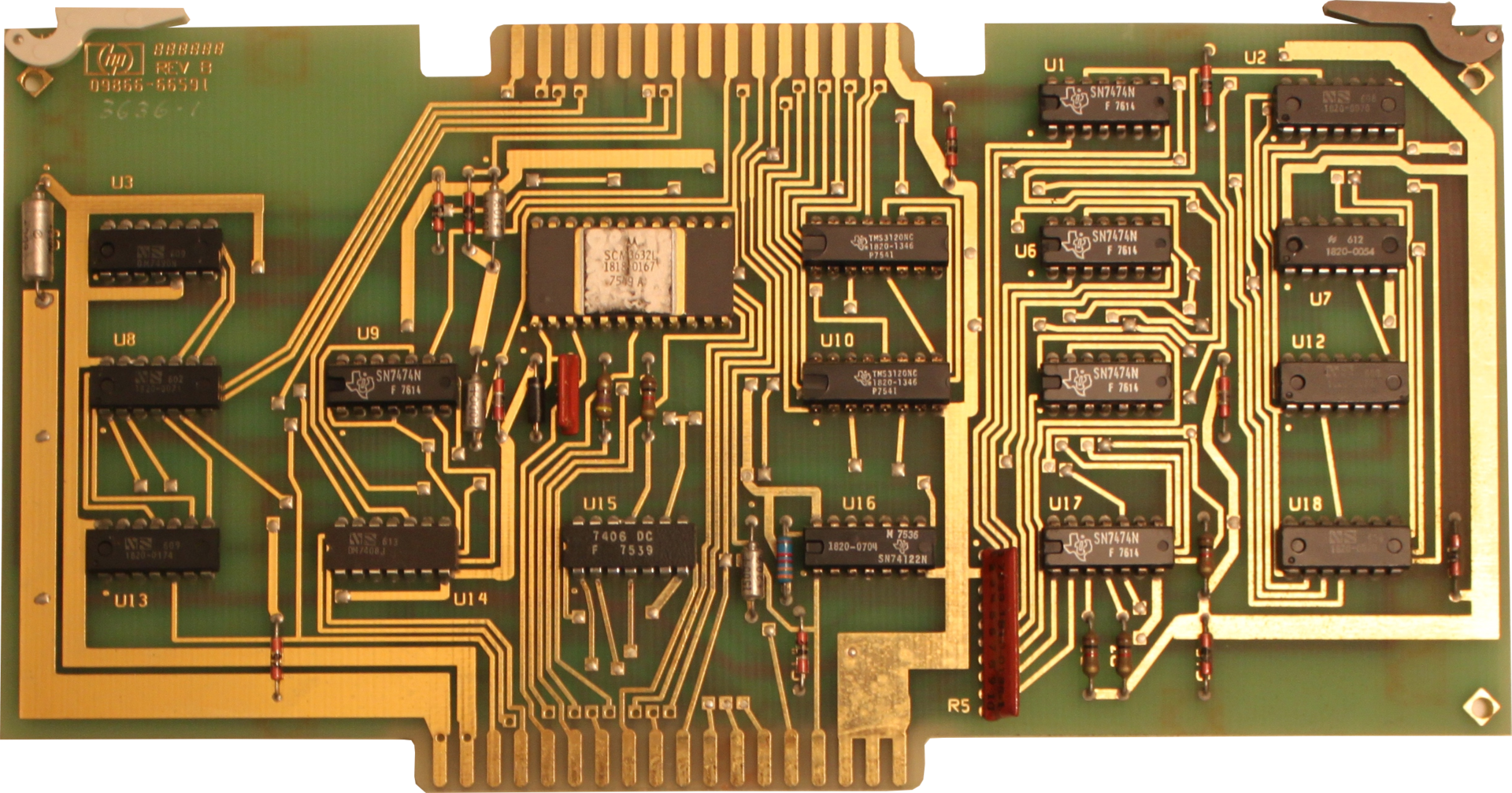
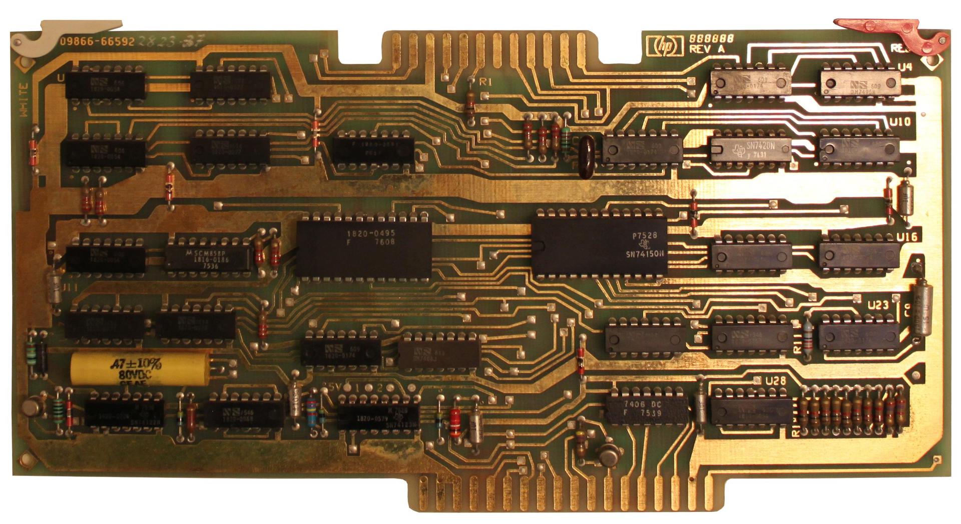
The next step was to track the signal in the operating device to the U19 chip, but suddenly it turned out that there was no such chip on the board! Before that, I had no need to verify that the electronic circuit corresponds to this particular board. I just assumed it was. In my HP9866, there were two different modules from the module - the above-mentioned automatic machine 09866-66591 and control board 09866-66592. The reason for the differences was that I had HP9866B, and the diagrams were made for HP9866A!
The operating machine had another ROM for character encoding - SCM3632 from Motorola, with an HP ID of 1818-0167. Two quad-shift TMS3120 shift registers ( quadruple, four registers with separate legs in one case ) from Texas Instruments were used instead of three MM5052.
I decided that HP changed only the PCB layout, but the signals for the connector with the cross-board left the same. Rapid testing of the RotEn signal revealed that it comes from the sixth pin of the U8 chip, which is 1820-0071. Google told me that this is 7440. It is fully consistent with the scheme that Tony made.
Control board I can not say exactly what has changed in it. However, the microcode ROM has the same nomenclature as in the diagram, so my inventions, made earlier, must still be correct. That is, the input signals and control codes should be fed to the 74150 ones that I was thinking about.
The next step should be the measurement of signals on the U8, U3 (7490) chips and on the U13 with the number 1820-0174, behind which lies 7404.
New glitch
While debugging the printer, suddenly, strobe pulses stopped coming from the calculator. I immediately tried if another I / O module was working — a tape drive. It did not work ... Let me remind you that I had previously replaced the card in 9830 with a card from 9810, since it worked better. However, it seems that now she is also failing.
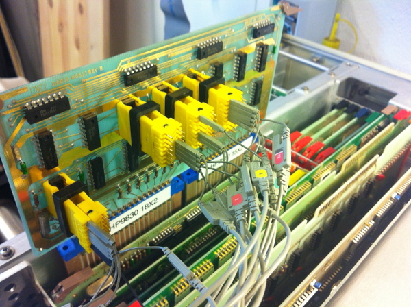
Let's start debugging this board. After reading the manual from Tony and studying the diagrams, I had an idea that the ribbon usage flag was incorrectly determined, which goes through the Bus_IO_Rd / ( nCFI signal in a newer version of the scheme from Brent ). After that, it passes the three-input NAND-valve 7410, monostable multivibrator 74121, trigger 7474, and then the I / O-flag is generated at the output of the 7453 valve. Therefore, I connected the analyzer probes to these microcircuits, designated as U7, U8, U9 and U13.
By the way, pay attention to the use of extension boards. Now, if necessary, you can easily bring the probes to the contacts of the connector with the cross-board.
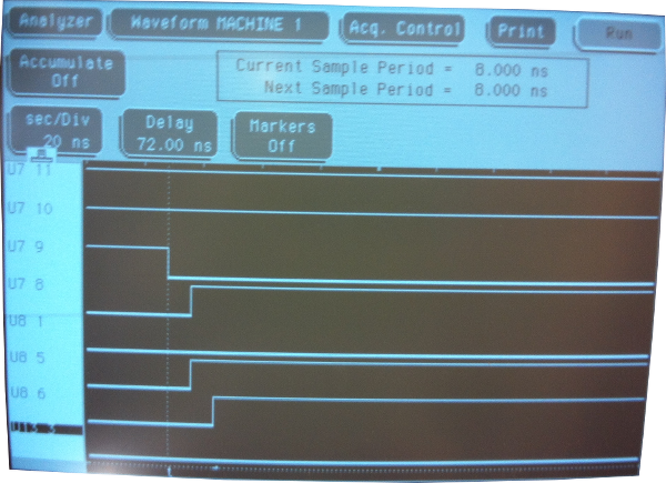
The HP1664 analyzer triggered a trigger for a drop in the signal from pin 9 on the U7 chip. The output signal on pin 1 of the U8 (74121) chip was quite entertaining.
It seems that this signal is always at a low level, although the non-inverted output is healthy ( pin1 = NOT pin6 for 74121, and, judging by the picture, U8 6 is fine ). Replacing with 74121 from another board (it’s very annoying that 7412X and 74123 were present in my relatively large set of 74XX chips, although 74122 and 74123 were present) gave a much better result.
Now the commands for the drive have worked exactly the same as with the replacement card from 9810 (before it broke).
Returning to the printer
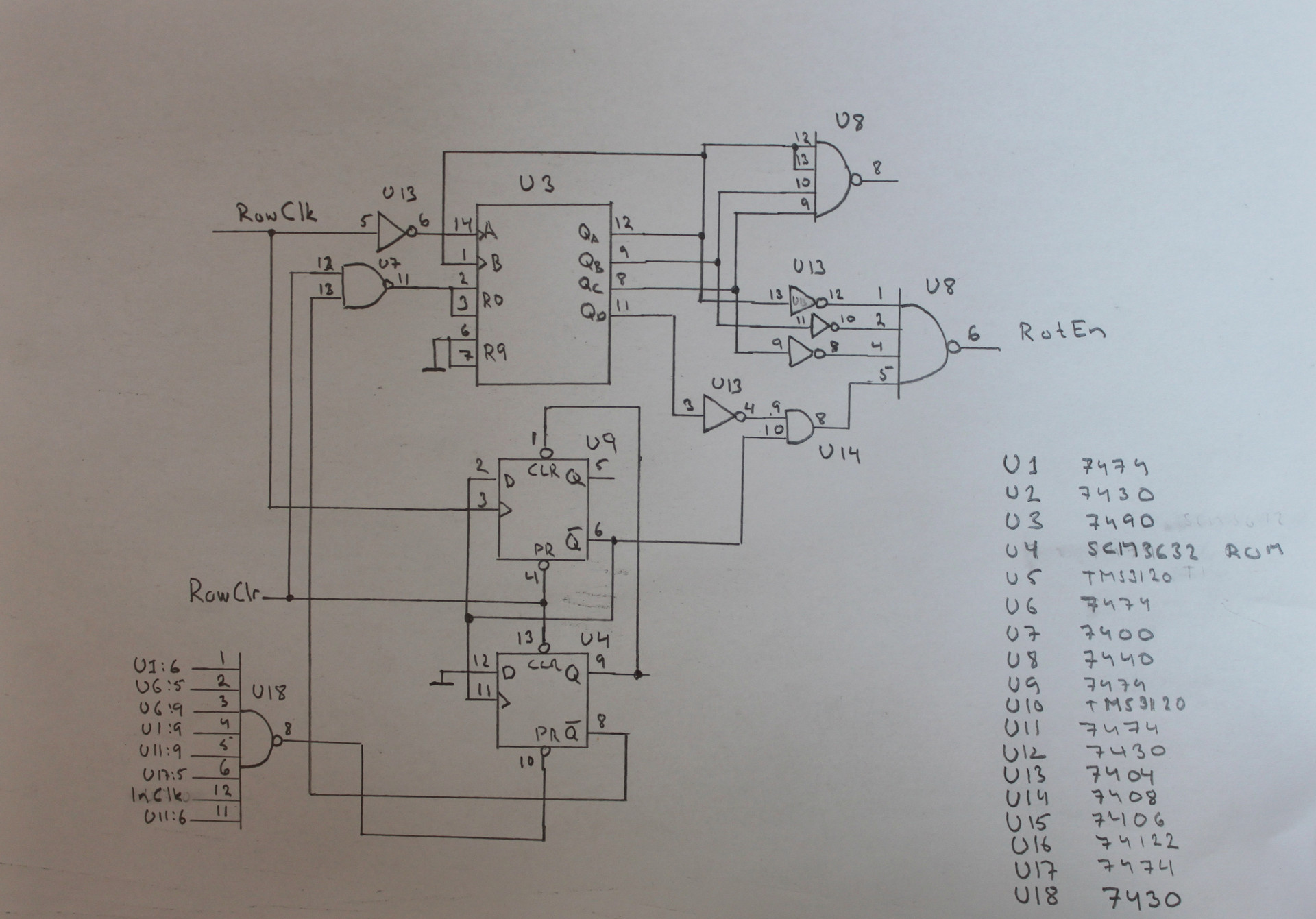
Before the I / O board went out of order, I tracked the signal from RotEn, which never changed. The signal was generated by an operating machine board, which was different from the schemes I used.
Therefore, I drew my own actual version.
I connected the analyzer to U3, U7, U8, U13 and U14. Immediately after turning on the printer, I noticed that the output pin 4 to U13 (7404 inverter) was constantly switching from one level to another, while the Qd signal from 7490, which was always low, was fed to the input. This is definitely wrong behavior.
After replacing the 7404 with a new chip, the printer began to stretch the paper, line by line, and not hang on waiting, as before. It did not print anything, because I dismantled the printhead and its power supply in order to prevent any potential damage in case the logic is faulty.
Back in work!
I just checked the signal bank, which chooses which group of needles in the head to use (The board responsible for working with the needles was one, but it contained 4 groups of 5 needles, since the characters were set by a 5x7 matrix. To optimize the temperature and power consumption, the engineers decided to use these groups sequentially.Group 1 prints lines for characters in positions 1, 5, 9, ..., 79, group 2 - 2, 6, ... 78, etc. That is, in fact, four passes are made. This signal just sets the number of the passage. ). Everything was OK. It was embarrassing that the marking marked the location of the first pin in the opposite of where it should be, the end of the connector. However, I returned the print head to its place and tested the printer. He worked!
I made a small video with information about the calculator and its repair.
It is interesting to see the last part of the video, which shows the process of work.
Replaced parts
I replaced the following components:
- Two lamps for indicators
- Lamp in magnetic tape drive
- BCD ALU 256 x 4 PROM on the board of the operation machine in the calculator
- 74121 on the I / O processor board
- 7404 on the operating machine board in the printer
- Five broken keys
- Three lost keys
- Two o-ring'a for wheels in a tape drive
Future plans
I still have a disk subsystem of two heavy drives for 14 "cartridges (plus a pallet for fixed storage), two heavy power supplies, a control module, cables and a ROM cartridge. All this is in stock, but I will leave it this is for the following years.
Links to useful materials
- hpmuseum.net has this good page on the HP9830
- Repair guide for the HP98x0 that Tony Duell has written
- Hand drawn schematics of HP9830A made by Tony Duell
- Brent Hilpert has this very good page on the HP9830 with schematics and a lot more
- A repair guide for the HP9866A written by Tony Duell
- Hand drawn schematics for the HP9866A made by Tony Duell
- A HP9830 emulator
- hp9830.com
- A web page by Rob Ferguson who also restored a HP9830
- HP98xx story
- hpmusuem.org page on the HP9830
- Andreas page on the HP9810
Source: https://habr.com/ru/post/244033/
All Articles