Overview of the Hantek DSO-6022BL USB Oscilloscope with a Logic Analyzer and Diffuser
Good afternoon, Habr!
I offer to the attention of a respected audience a review of the oscilloscope / logic analyzer Hantek6022BL.

Interested please under the cat.
Oscilloscope:
Logic analyzer:
Are common
')
Appearance is uniquely 5. Brilliant and stylish aluminum body, plastic lining, Hantek mirror inscription. Immediately obvious, the design does not save here.

Front view. Two probes BNC connectors, logic analyzer connector, calibration contacts. Everything is predictable.
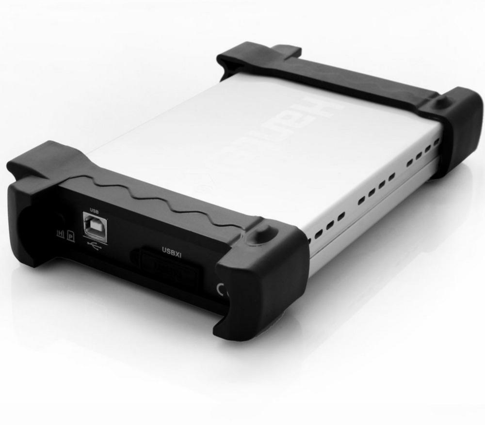
USB, mysterious button and no less mysterious hatch with the inscription USBXI, under which there is a strange connector.
The kit includes the oscilloscope itself, a USB cable, two cables to the logic analyzer, 20 terminals for the logic analyzer, two probes to the oscilloscope complete with multi-colored marking rings and screwdrivers for adjusting the frequency response of the probe. Probes are called PP-80, but they have a bandwidth of 60 MHz, not 80, as one might think. The reasons for this lie, it seems to me, in the properties of the gloomy Chinese genius.
There is also a CD with software, a thing of little use these days.
At first glance, an excellent thing. Compact, lightweight device, in a very high-quality aluminum case (like Ipad, the seller writes on aliexpress).
In addition to the listed interfaces, there is a latching button on the device case (and this is not a power switch, as one might think) and a connector marked USBXI, not described in the documentation, and probably intended to connect several devices to each other. There are also contacts built-in calibration generator.
It is time to install the software and turn on the device.
The easiest way to download the software is from the Russian site hantek.ru ; registration is not even required, unlike the “main” site hantek.com . Instruction in English, software, too, although the site is and Russification.
So, the software has been downloaded, installed, the device is connected to the computer. We connect the probes, connect them to the contacts of the calibration generator and run the program of the oscilloscope. We see two signals of a rectangular (almost) shape. Using a screwdriver, adjust the probes so that the signals acquire an ideal rectangular shape.
After the device has warmed up within 20 minutes (according to the instructions), we do self-calibration. It seems that nothing has changed, but my heart has become calmer.
After playing a little bit with the sensitivity knobs of the channels and the sweep time (nothing new has been invented here), we will move on to a deeper study of the software.
The trigger has a single trigger mode: Edge (on the front), the user can select the source (channel 1 or channel 2 and front, positive or negative).
<lyrical digression>
Beg a lyrical digression. When I was studying at the institute, some teachers didn’t like expressions like “front front” and “back front”. The front is only the front, by definition, they said, so you just need to say “front”, and what is called the “back front” is correctly called a “recession.” In my heart, I agree with them, but here I will use the phrases “front front” and “back front”.
</ lyrical digression>
Autorun, “Normal” mode, and one-time start are provided. The trigger has no more “tricky” modes.
The horizontal sweep is adjustable from 1 ns (a completely useless range for this device) to 3000 seconds. There is a display mode with horizontal scanning (x (t), y (t)) and with XY mode (it is convenient, for example, for Lissajous figures).
The sensitivity of the channels is adjustable within 200mV / div to 5V / div with a probe ratio of 1: 1, and allows you to work with probes with dividers up to 1: 10,000 (honestly, I have never seen anything like this, it should be a very high-voltage thing).
The trigger trigger level and horizontal shift can be changed simply with the mouse, but the values of these values are not displayed anywhere. The moment the trigger is triggered is not tied to any divisions on the oscillogram, nor to the center of the screen, nor to anything at all.
It is displayed as the third waveform and can display the sum, difference, product and the partial values of the signal in channels A and B, as well as the spectrum (FFT). For FFT, you can select the window type: rectangular, Hamming, Hanning, Blackman. You can select a linear or logarithmic amplitude scale.
In fact, this is not a special channel; it is just a display of a previously saved signal next to the current ones, for example, for comparison.
The period and frequency of the signal, the time of rise and fall of the signal, the pulse width and the width of the gap between the pulses in units of time and as a percentage of the full period are measured.
The maximum and minimum values of the signal, the voltage “from peak to peak”, the voltage of the “top” and “base” of the pulse, the average value, the root-mean-square value, positive and negative overshoot in percent.
Perhaps the only mode that is more convenient in the "virtual" oscilloscope than in the "present". Simply select the rectangle on the screen with the mouse and see deltaT and deltaV. There are three curtain modes: vertical, horizontal and “cross”, that is, both are at once. Why do we need the first two, it is not clear.
"Magic" button that adjusts the optimal (according to the program) display mode.
Due to the discrete nature of the measurements, the displayed data can be interpolated as follows: “stepwise” mode, that is, no interpolation, “linear” mode and interpolation of the form of sin (x) / x, which, theoretically, should be the most accurate. Unfortunately, the effect of its inclusion was never seen.
Display by vectors or points, display of a coordinate grid, brightness of oscillograms and grids, nothing unusual.
Waveforms can be saved in different formats: txt, xls, doc and bmp. The first three represent simply the values of the samples in text form, the latter is a screenshot of the waveform. There is also a ref-format, designed to work with the ref-channel.
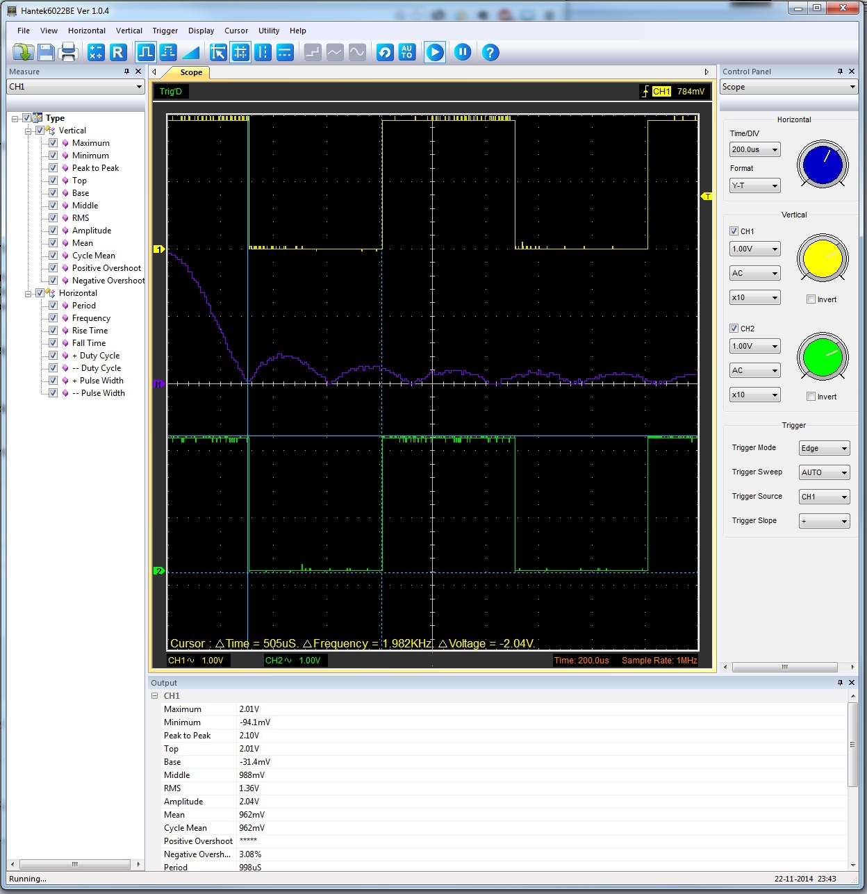
The picture above shows the program interface with two signals at the inputs A and B, with the math channel to which FFT is output, with the cursors and with the measurement mode turned on.
In general, the oscilloscope as an oscilloscope, only the simplest functions, but work fine. Could do better. Grade 4.
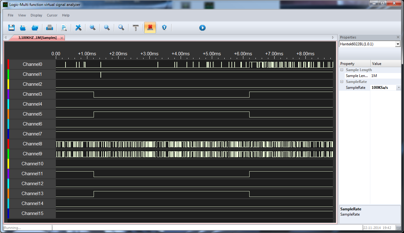
The logic analyzer is displayed in a separate window.
We see 16 signals and ... everything. No settings, no launch conditions, nothing at all. Signal triggering is performed manually with the button. However, there is one setting, SampleRate can be selected from 100 kSa / s to 48 kSa / s. Capturing signals occurs before the memory is full (1M samples).
The logic analyzer is in no way connected with the oscilloscope, it can neither be triggered by its trigger, nor can it be triggered, nor can it be triggered on the front of any logic signal, nor, all the more, by more complex events and conditions.
The analyzer interface, after capturing signals, begins to shamelessly brake.
Those who worked with real analyzers will cry with burning tears.
In general, for the analyzer, the rating is 2 plus (at least something works). Maybe there is some hope that the logic analyzer will work better in the next software version.
There is nothing good in this regard yet. There is an alternative software for the DSO-6022BE, but it did not work with this model. In addition, it is practically no different from the native, except for small changes in the design of the GUI.
There is software for Hantek devices under Linux, but it does not support the DSO-6000 line at all.
Windows 7 did not automatically find anything, of course, she had to specify the folder with the drivers manually.
As you can understand from the manual, this button is designed to invoke software. However, it does not fulfill this function, and is currently just a button for beauty. The same can be said about the USBXI connector. Even if it is intended for combining several devices into one, neither the cable nor any traces of supporting this function could be found in the software.
This is, of course, a toy. If using an oscilloscope is your daily business, then it is better to buy a normal oscilloscope, without the prefix "USB". Even an inexpensive oscilloscope has much more features and functions. Not to mention the logic analyzer.
However, if you rarely need an oscilloscope, or if your budget is very limited, then you can work with this model.
The manufacturer has laid out the SDK, which can open up some non-trivial possibilities of using the device, for example, in automated measuring complexes. But I have not looked at the SDK yet.
What's inside it?
Remove the plastic lining and unscrew the front and back covers. Now you can remove the board.
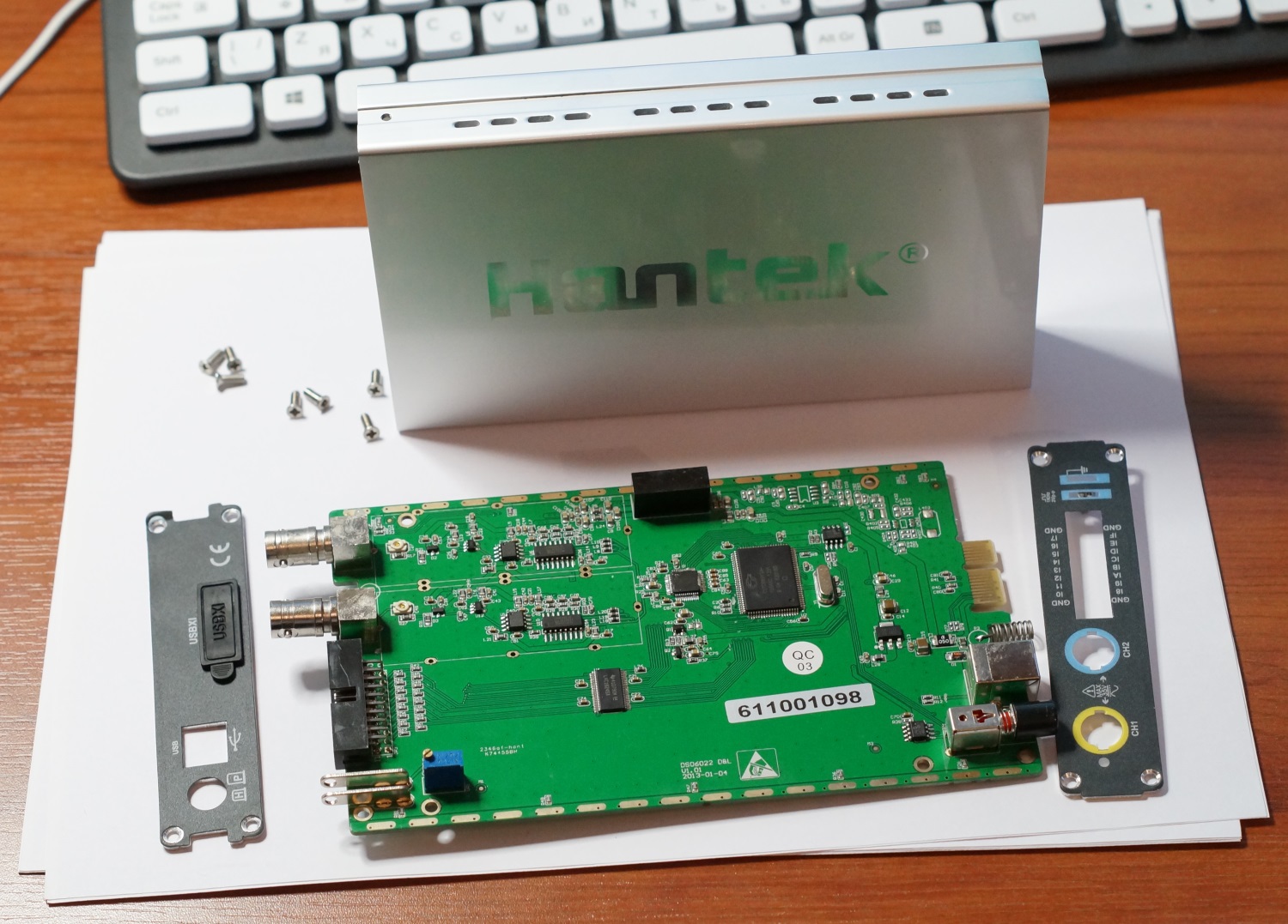
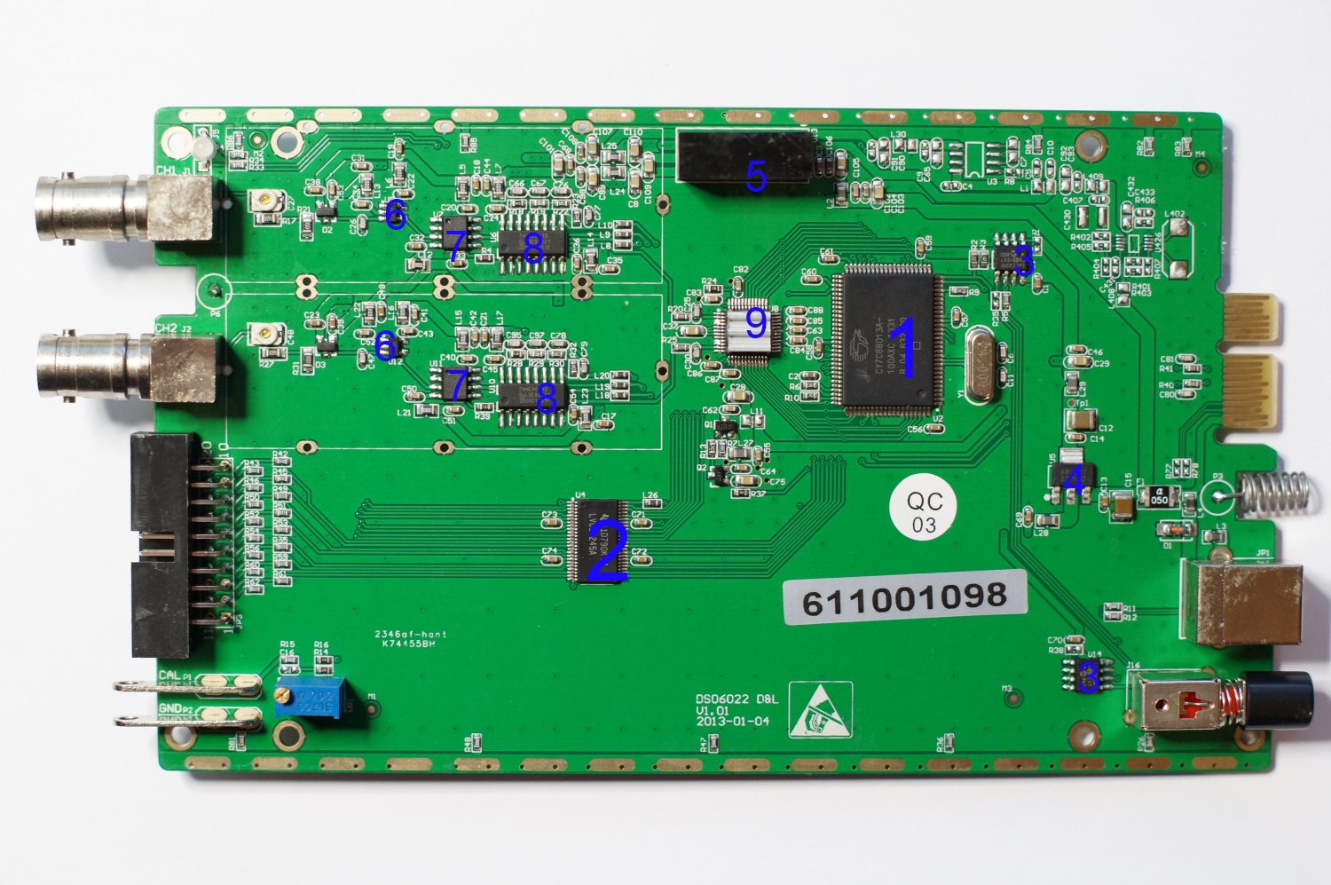
Photo board
What is what on this board? I numbered all the chips. Let's see what is what.
1. The “brains” is the Cypress micro7 microcontroller cy7c68013a-100axc ( http://www.cypress.com/?docID=45142 ). Microcontroller on 8051 core with High-speed USB interface. In principle, a clear choice. You do not need high speed from the processor, since all processing takes place on the computer side, but you need a fast USB.
2. SN74LVC16245A ( http://www.ti.com/lit/ds/symlink/sn74lvc16245a.pdf ) is a front-end logic analyzer. Normal 16-bit buffer.
3. 24LC02BI ( http://ww1.microchip.com/downloads/en/DeviceDoc/21709J.pdf ) - 2 kb EEPROM for storing any settings. Why are two of them, it is not clear.
4. AMS1117-3.3 ( http://www.advanced-monolithic.com/pdf/ds1117.pdf ) - 3.3V linear power supply stabilizer.
5. Inout A0505S-2WR ( http://pdf1.alldatasheet.com/datasheet-pdf/view/611588/MORNSUN/A0505S-2WR2.html ) - + 5V converter to bipolar voltage of 5V to power the analog front end.
6. AD8065 ( http://www.analog.com/static/imported-files/data_sheets/AD8065_8066.pdf ) is an operational amplifier with FET inputs and a frequency band of 145 MHz.
7. EL5166 ( http://www.intersil.com/content/dam/Intersil/documents/el51/el5166-67.pdf ) - Intersil broadband operational amplifier (band with a single gain of 1.4 GHz).
8. 74HC4051 ( http://www.nxp.com/documents/data_sheet/74HC_HCT4051.pdf ) - 8-channel analog multiplexer / demultiplexer
9. The most interesting chip, the ADC, is hidden under the radiator. A slight heating with a soldering iron, and the radiator peeled off, and under it was AD9288 ( http://www.analog.com/static/imported-files/data_sheets/AD9288.pdf ) - 8-bit ADC, 2 channels of 100 MSa / s.
Everything is done very simply and minimalist, but neat. Too simple, I was hoping to see at least some FPGAs. Analog frontend has a large frequency margin, which is very good. In "adult" oscilloscopes, the same hardware is often used for the whole model range, and the frequency band for younger models is cut off programmatically for marketing reasons. Knowing the necessary dance with a tambourine, you can get from the younger model of the older, using the capabilities of iron at 100%.
But in this case, the older models from the same line have a sampling frequency of 150 and 250 MHz, that is, at least another ADC.
Price at the time of purchase: 3866 rubles (on aliexpress). The price on the official Russian website hantek 4400 rubles, for example.
Is it worth the money, you decide. In my opinion, if the device is purchased for simple tasks (playing with arduine, for example), then you can hardly find something cheaper with comparable parameters. And for honest work, I recommend to spend money on a portable desktop oscilloscope.
That's all for now. Request for noticed inaccuracies and errors to report to the PM.
I offer to the attention of a respected audience a review of the oscilloscope / logic analyzer Hantek6022BL.
Interested please under the cat.
Specifications
Oscilloscope:
- Channels: 2
- bandwidth: 20 MHz
- sampling rate: 48 Msa / s
- memory capacity: 1Ms
- interface: USB 2.0
Logic analyzer:
- logical channels: 16
- bandwidth: 10 MHz
- memory capacity: 48Msa
- memory depth: 1 Ms
Are common
- Dimensions: 205 x 120 x35
- power supply: from USB port
- weight: 0.382 kg
')
Appearance
Appearance is uniquely 5. Brilliant and stylish aluminum body, plastic lining, Hantek mirror inscription. Immediately obvious, the design does not save here.
Front view. Two probes BNC connectors, logic analyzer connector, calibration contacts. Everything is predictable.
USB, mysterious button and no less mysterious hatch with the inscription USBXI, under which there is a strange connector.
Equipment
The kit includes the oscilloscope itself, a USB cable, two cables to the logic analyzer, 20 terminals for the logic analyzer, two probes to the oscilloscope complete with multi-colored marking rings and screwdrivers for adjusting the frequency response of the probe. Probes are called PP-80, but they have a bandwidth of 60 MHz, not 80, as one might think. The reasons for this lie, it seems to me, in the properties of the gloomy Chinese genius.
There is also a CD with software, a thing of little use these days.
Subjective impressions
At first glance, an excellent thing. Compact, lightweight device, in a very high-quality aluminum case (like Ipad, the seller writes on aliexpress).
In addition to the listed interfaces, there is a latching button on the device case (and this is not a power switch, as one might think) and a connector marked USBXI, not described in the documentation, and probably intended to connect several devices to each other. There are also contacts built-in calibration generator.
It is time to install the software and turn on the device.
Beginning of work
The easiest way to download the software is from the Russian site hantek.ru ; registration is not even required, unlike the “main” site hantek.com . Instruction in English, software, too, although the site is and Russification.
So, the software has been downloaded, installed, the device is connected to the computer. We connect the probes, connect them to the contacts of the calibration generator and run the program of the oscilloscope. We see two signals of a rectangular (almost) shape. Using a screwdriver, adjust the probes so that the signals acquire an ideal rectangular shape.
After the device has warmed up within 20 minutes (according to the instructions), we do self-calibration. It seems that nothing has changed, but my heart has become calmer.
After playing a little bit with the sensitivity knobs of the channels and the sweep time (nothing new has been invented here), we will move on to a deeper study of the software.
Scan
The trigger has a single trigger mode: Edge (on the front), the user can select the source (channel 1 or channel 2 and front, positive or negative).
<lyrical digression>
Beg a lyrical digression. When I was studying at the institute, some teachers didn’t like expressions like “front front” and “back front”. The front is only the front, by definition, they said, so you just need to say “front”, and what is called the “back front” is correctly called a “recession.” In my heart, I agree with them, but here I will use the phrases “front front” and “back front”.
</ lyrical digression>
Autorun, “Normal” mode, and one-time start are provided. The trigger has no more “tricky” modes.
The horizontal sweep is adjustable from 1 ns (a completely useless range for this device) to 3000 seconds. There is a display mode with horizontal scanning (x (t), y (t)) and with XY mode (it is convenient, for example, for Lissajous figures).
Channel sensitivity
The sensitivity of the channels is adjustable within 200mV / div to 5V / div with a probe ratio of 1: 1, and allows you to work with probes with dividers up to 1: 10,000 (honestly, I have never seen anything like this, it should be a very high-voltage thing).
The trigger trigger level and horizontal shift can be changed simply with the mouse, but the values of these values are not displayed anywhere. The moment the trigger is triggered is not tied to any divisions on the oscillogram, nor to the center of the screen, nor to anything at all.
Channel "mathematics"
It is displayed as the third waveform and can display the sum, difference, product and the partial values of the signal in channels A and B, as well as the spectrum (FFT). For FFT, you can select the window type: rectangular, Hamming, Hanning, Blackman. You can select a linear or logarithmic amplitude scale.
"Ref" channel
In fact, this is not a special channel; it is just a display of a previously saved signal next to the current ones, for example, for comparison.
Measurement mode
"Horizontal" measurements
The period and frequency of the signal, the time of rise and fall of the signal, the pulse width and the width of the gap between the pulses in units of time and as a percentage of the full period are measured.
"Vertical" measurements
The maximum and minimum values of the signal, the voltage “from peak to peak”, the voltage of the “top” and “base” of the pulse, the average value, the root-mean-square value, positive and negative overshoot in percent.
Cursor measurement mode
Perhaps the only mode that is more convenient in the "virtual" oscilloscope than in the "present". Simply select the rectangle on the screen with the mouse and see deltaT and deltaV. There are three curtain modes: vertical, horizontal and “cross”, that is, both are at once. Why do we need the first two, it is not clear.
Auto install
"Magic" button that adjusts the optimal (according to the program) display mode.
Interpolation
Due to the discrete nature of the measurements, the displayed data can be interpolated as follows: “stepwise” mode, that is, no interpolation, “linear” mode and interpolation of the form of sin (x) / x, which, theoretically, should be the most accurate. Unfortunately, the effect of its inclusion was never seen.
Display settings
Display by vectors or points, display of a coordinate grid, brightness of oscillograms and grids, nothing unusual.
Saving data
Waveforms can be saved in different formats: txt, xls, doc and bmp. The first three represent simply the values of the samples in text form, the latter is a screenshot of the waveform. There is also a ref-format, designed to work with the ref-channel.
The picture above shows the program interface with two signals at the inputs A and B, with the math channel to which FFT is output, with the cursors and with the measurement mode turned on.
In general, the oscilloscope as an oscilloscope, only the simplest functions, but work fine. Could do better. Grade 4.
Logic analyzer
The logic analyzer is displayed in a separate window.
We see 16 signals and ... everything. No settings, no launch conditions, nothing at all. Signal triggering is performed manually with the button. However, there is one setting, SampleRate can be selected from 100 kSa / s to 48 kSa / s. Capturing signals occurs before the memory is full (1M samples).
The logic analyzer is in no way connected with the oscilloscope, it can neither be triggered by its trigger, nor can it be triggered, nor can it be triggered on the front of any logic signal, nor, all the more, by more complex events and conditions.
The analyzer interface, after capturing signals, begins to shamelessly brake.
Those who worked with real analyzers will cry with burning tears.
In general, for the analyzer, the rating is 2 plus (at least something works). Maybe there is some hope that the logic analyzer will work better in the next software version.
Alternative software
There is nothing good in this regard yet. There is an alternative software for the DSO-6022BE, but it did not work with this model. In addition, it is practically no different from the native, except for small changes in the design of the GUI.
There is software for Hantek devices under Linux, but it does not support the DSO-6000 line at all.
Drivers
Windows 7 did not automatically find anything, of course, she had to specify the folder with the drivers manually.
Mysterious button and connector on the back panel
As you can understand from the manual, this button is designed to invoke software. However, it does not fulfill this function, and is currently just a button for beauty. The same can be said about the USBXI connector. Even if it is intended for combining several devices into one, neither the cable nor any traces of supporting this function could be found in the software.
Overall rating
This is, of course, a toy. If using an oscilloscope is your daily business, then it is better to buy a normal oscilloscope, without the prefix "USB". Even an inexpensive oscilloscope has much more features and functions. Not to mention the logic analyzer.
However, if you rarely need an oscilloscope, or if your budget is very limited, then you can work with this model.
Sdk
The manufacturer has laid out the SDK, which can open up some non-trivial possibilities of using the device, for example, in automated measuring complexes. But I have not looked at the SDK yet.
Geekporn
What's inside it?
Remove the plastic lining and unscrew the front and back covers. Now you can remove the board.
Photo board
What is what on this board? I numbered all the chips. Let's see what is what.
1. The “brains” is the Cypress micro7 microcontroller cy7c68013a-100axc ( http://www.cypress.com/?docID=45142 ). Microcontroller on 8051 core with High-speed USB interface. In principle, a clear choice. You do not need high speed from the processor, since all processing takes place on the computer side, but you need a fast USB.
2. SN74LVC16245A ( http://www.ti.com/lit/ds/symlink/sn74lvc16245a.pdf ) is a front-end logic analyzer. Normal 16-bit buffer.
3. 24LC02BI ( http://ww1.microchip.com/downloads/en/DeviceDoc/21709J.pdf ) - 2 kb EEPROM for storing any settings. Why are two of them, it is not clear.
4. AMS1117-3.3 ( http://www.advanced-monolithic.com/pdf/ds1117.pdf ) - 3.3V linear power supply stabilizer.
5. Inout A0505S-2WR ( http://pdf1.alldatasheet.com/datasheet-pdf/view/611588/MORNSUN/A0505S-2WR2.html ) - + 5V converter to bipolar voltage of 5V to power the analog front end.
6. AD8065 ( http://www.analog.com/static/imported-files/data_sheets/AD8065_8066.pdf ) is an operational amplifier with FET inputs and a frequency band of 145 MHz.
7. EL5166 ( http://www.intersil.com/content/dam/Intersil/documents/el51/el5166-67.pdf ) - Intersil broadband operational amplifier (band with a single gain of 1.4 GHz).
8. 74HC4051 ( http://www.nxp.com/documents/data_sheet/74HC_HCT4051.pdf ) - 8-channel analog multiplexer / demultiplexer
9. The most interesting chip, the ADC, is hidden under the radiator. A slight heating with a soldering iron, and the radiator peeled off, and under it was AD9288 ( http://www.analog.com/static/imported-files/data_sheets/AD9288.pdf ) - 8-bit ADC, 2 channels of 100 MSa / s.
Everything is done very simply and minimalist, but neat. Too simple, I was hoping to see at least some FPGAs. Analog frontend has a large frequency margin, which is very good. In "adult" oscilloscopes, the same hardware is often used for the whole model range, and the frequency band for younger models is cut off programmatically for marketing reasons. Knowing the necessary dance with a tambourine, you can get from the younger model of the older, using the capabilities of iron at 100%.
But in this case, the older models from the same line have a sampling frequency of 150 and 250 MHz, that is, at least another ADC.
Price
Price at the time of purchase: 3866 rubles (on aliexpress). The price on the official Russian website hantek 4400 rubles, for example.
Is it worth the money, you decide. In my opinion, if the device is purchased for simple tasks (playing with arduine, for example), then you can hardly find something cheaper with comparable parameters. And for honest work, I recommend to spend money on a portable desktop oscilloscope.
That's all for now. Request for noticed inaccuracies and errors to report to the PM.
Source: https://habr.com/ru/post/243937/
All Articles