Recovery PDP 11/04. Terminal LA30 Decwriter
Continuation of the translation of the article on the restoration of one old interesting machine. In the first part, we adjusted the main board unit. In the second - the tape station TU60. Many heavy pictures. Italic my comments.
Now I have started the final part of my quest - to get a good terminal, which would be as vintage as the main system. I am lucky that I have LA30 in storage, which I am now going to begin to recover. Our copy was made in early 1973. Although, the print heads were apparently replaced in 1979.
LA30, apparently, was one of the first dot-matrix printers, which makes it interesting, in itself, even in isolation from the PDP-11.
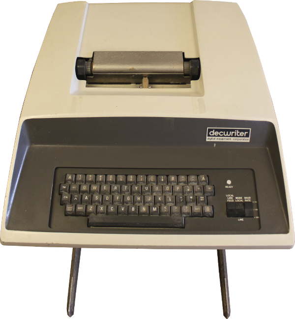
Printing terminal with a really nice vintage look! It is also heavy. The body is made of casting (it seems to me) of aluminum, and the top cover is made of fiberglass, reinforced with ordinary plastic.
')
The decwriter on the right has a data rate switch, which is why I think it was the LA30S for the serial port, but on the information plate behind it is written LA30P. In addition, it does not have two cards that are needed to connect via a serial port.
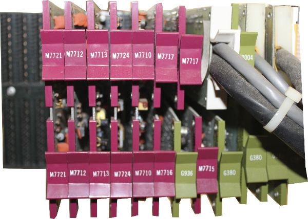
All printer control logic is transistor ( TTL ), with the exception of ROM for decoding characters, a keyboard coder and an optional UART.
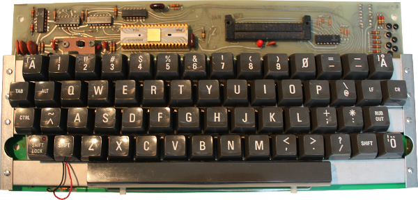
After cleaning, the keyboard looks pretty dignified. The layout is slightly different from modern keyboards. Microchip keyboard coder is very beautiful, is not it? Very early BIS, created by SMC.
I started working with fixing capacitors. Although all the capacitors were in quite good condition. The leakage current is 100µA at the worst of them. Not bad, especially after 40 years. After that, I cleaned the printheads from old ink.
When (and if) I make it work, I will still have a serious problem: this is a parallel terminal that requires the M7910 fee on the PDP-11. I don't have one like that. Another option is to find two missing boards - M7731 and M7389, which, I think, is even more difficult. The last possibility is to assemble a small adapter on the Arudino from the parallel port to the serial port.
Pictured below is the LA30 printhead. The time stamp on it contains 1979. This means that the head has been replaced. It looks like this is the same head that was used in LA36 and LA180.

I tested the printheads, delivering 15V and ~ 2A to each coil for an extremely short amount of time. Only 2 of the 7 needles reacted. Therefore, I bought a special recommended oil - Omega 636, and, by the way, it contains something called allspice. Liquid oil and a few days of rest brought life to three additional needles, and the remaining two need a little pressure for release. I hope that when I return the heads to the printer, these needles will also work.
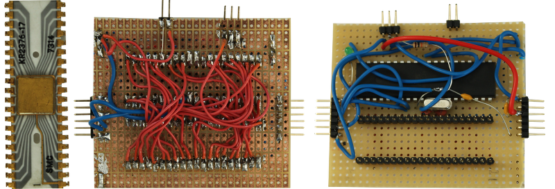
KR2376 from SMC, a pMOS chip that performs keyboard coding, was broken. Looking for a suitable replacement would not be easy and very expensive. I made my own equivalent on AVR.
Since the keyboard is of capacitive type, it means that each and every key is a transistor. The collector of which is connected to the X-matrix, and the emitter to Y. The base, in turn, is connected to a variable capacitor, which is formed by the moving part of the key and the board itself. On the other hand, an oscillator is connected to this capacitor.
The original SMC chip is on the left, and my replacement is on the right.
For Arudino, there is a pretty good keyboard library that needed only a few minor edits. In addition to the faulty encoder, there was a micro-crack on the keyboard board, which I patched with a small amount of solder. After that, the keyboard worked fine!
Software can be downloaded here .
The power supply contains a large transformer and four electrolytic capacitors. One of the transformer windings is connected to an AC capacitor to form a ferroresonant circuit. Thus, the power supply becomes more resistant to power glitches. It saves energy in the coil and the capacitor. But this capacitor is already very old and most likely contains polychlorinated biphenyls. The nomenclature of the capacitor was recorded in the list of elements of the board, so I decided to replace it just in case, before continuing work. I found a suitable capacitor from Cornell-Dublier

Old replacement capacitor
While I was waiting for delivery, I rechecked electrolytic capacitors. They were all right, and as soon as the AC capacitor arrived, I was able to run the power supply under the test load without any problems. All specifications were excellent.
My homemade keyboard coder was a bit clumsy and didn’t look very cool. For self-education, I decided to do the layout and order a fee in China. The result was great!

Before starting the full test, I dismantled the printer in order to clean it and lubricate all the places where it was required. After reassembling the machine and raising it to the “ON” position, of course, nothing happened. The first problem was that there were two locking keys that must be in the correct position for the unit to be ready for operation. One of them checked that there is paper in the printer. When the printer is in the “READY” state, the “B INI L” signal is at a high level and the “READY” light on the keyboard glows pleasantly. In addition, a strobe pulse is generated from the keyboard to the control logic of the printer. The LA30 version with parallel connection does not have a LINE / LOCAL switch, so this option is not user adjustable, but it turns out that a logic circuit with this feature is present on the M7712 board, but is not used. When the “LCL ENA L” signal is sent through the AR2 pin on the M7712 board, it closes the printer for local operation.
And, voila, he really prints something when we type the text on the keyboard, but since there is no ribbon in his place, it is very difficult to understand what he is typing.
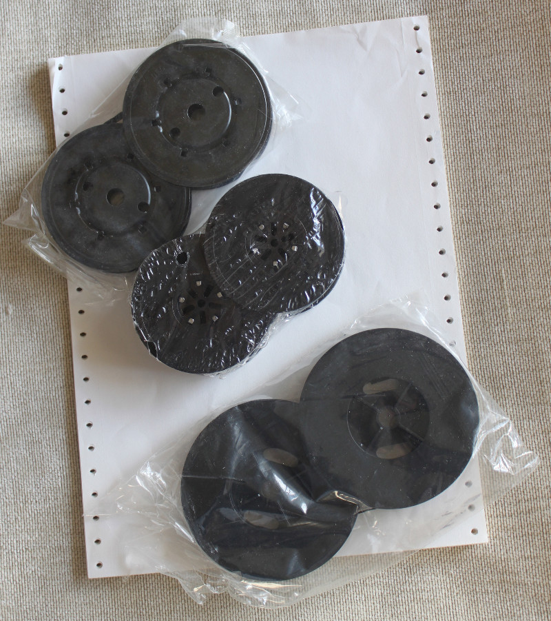
Looking through the repository, I found three different colored ribbons in the original packaging, still in heat shrinkage and even in folded paper. It looks like the top one is for LA30, and the bottom one is for LA36 / LA180. The average is unknown for sure, but perhaps for LS01 / Centronics 101. By the way, plain paper did not fit LA30. It needs 250mm paper instead of 216mm.
By inserting paper into the printer, I was able to check it, and he did print something, but this “something” was incorrect.
It seems that the last column of each character disappeared and, moreover, despite the keystrokes, only a limited set of characters appears on the paper. After checking with the ASCII table, you can see that two bits are stuck. Having traced these bits, we see that the correct values are supplied to the input of the symbol generator. Since the column counter is also located inside this generator, it becomes the main suspect. First you need to check the triggers marked in red.
It turned out that these chips are not working properly. Replace the broken 7474, produced by National Semiconductor (again NS!) In 1972, with ceramic from Fairchild and Texas Instruments.

There is one more trouble. The function "visible last character" does not work for the first time until the machine is warmed up. It starts functioning some time after the start. This is a function that moves the printhead two characters to the right after a timeout of 1 second so that the print character can see the last character typed. Great stuff if you use the machine as a console terminal. I traced the problem to a dead 1 second timeout generator. Red area in the diagram.
Initially, it looked like a non-working E14 (7440), but when I tested it with the use of a cooling spray, it turned out that this E12 meter (7493) behaves badly. Again the NS chip! Replacing it with a chip from TI, released in 1969, I saw that the generator was working.

The last problem is connected with the fact that the stepping motor was stalled during the carriage transfer on the filled line. Step pulses were just too fast. The LA30 has a separate unit that controls acceleration during carriage transfer. I simply lowered the maximum speed by setting one of the potentiometers in the G936 module.
With this last edit, the printer is working as it should!
LA30 Decwriter
Now I have started the final part of my quest - to get a good terminal, which would be as vintage as the main system. I am lucky that I have LA30 in storage, which I am now going to begin to recover. Our copy was made in early 1973. Although, the print heads were apparently replaced in 1979.
LA30, apparently, was one of the first dot-matrix printers, which makes it interesting, in itself, even in isolation from the PDP-11.
Printing terminal with a really nice vintage look! It is also heavy. The body is made of casting (it seems to me) of aluminum, and the top cover is made of fiberglass, reinforced with ordinary plastic.
')
The decwriter on the right has a data rate switch, which is why I think it was the LA30S for the serial port, but on the information plate behind it is written LA30P. In addition, it does not have two cards that are needed to connect via a serial port.
All printer control logic is transistor ( TTL ), with the exception of ROM for decoding characters, a keyboard coder and an optional UART.
After cleaning, the keyboard looks pretty dignified. The layout is slightly different from modern keyboards. Microchip keyboard coder is very beautiful, is not it? Very early BIS, created by SMC.
I started working with fixing capacitors. Although all the capacitors were in quite good condition. The leakage current is 100µA at the worst of them. Not bad, especially after 40 years. After that, I cleaned the printheads from old ink.
When (and if) I make it work, I will still have a serious problem: this is a parallel terminal that requires the M7910 fee on the PDP-11. I don't have one like that. Another option is to find two missing boards - M7731 and M7389, which, I think, is even more difficult. The last possibility is to assemble a small adapter on the Arudino from the parallel port to the serial port.
Allspice?
Pictured below is the LA30 printhead. The time stamp on it contains 1979. This means that the head has been replaced. It looks like this is the same head that was used in LA36 and LA180.
I tested the printheads, delivering 15V and ~ 2A to each coil for an extremely short amount of time. Only 2 of the 7 needles reacted. Therefore, I bought a special recommended oil - Omega 636, and, by the way, it contains something called allspice. Liquid oil and a few days of rest brought life to three additional needles, and the remaining two need a little pressure for release. I hope that when I return the heads to the printer, these needles will also work.
Homemade keyboard coder
KR2376 from SMC, a pMOS chip that performs keyboard coding, was broken. Looking for a suitable replacement would not be easy and very expensive. I made my own equivalent on AVR.
Since the keyboard is of capacitive type, it means that each and every key is a transistor. The collector of which is connected to the X-matrix, and the emitter to Y. The base, in turn, is connected to a variable capacitor, which is formed by the moving part of the key and the board itself. On the other hand, an oscillator is connected to this capacitor.
The original SMC chip is on the left, and my replacement is on the right.
For Arudino, there is a pretty good keyboard library that needed only a few minor edits. In addition to the faulty encoder, there was a micro-crack on the keyboard board, which I patched with a small amount of solder. After that, the keyboard worked fine!
Software can be downloaded here .
Power Supply
The power supply contains a large transformer and four electrolytic capacitors. One of the transformer windings is connected to an AC capacitor to form a ferroresonant circuit. Thus, the power supply becomes more resistant to power glitches. It saves energy in the coil and the capacitor. But this capacitor is already very old and most likely contains polychlorinated biphenyls. The nomenclature of the capacitor was recorded in the list of elements of the board, so I decided to replace it just in case, before continuing work. I found a suitable capacitor from Cornell-Dublier
Old replacement capacitor
While I was waiting for delivery, I rechecked electrolytic capacitors. They were all right, and as soon as the AC capacitor arrived, I was able to run the power supply under the test load without any problems. All specifications were excellent.
Enhanced encoder board
My homemade keyboard coder was a bit clumsy and didn’t look very cool. For self-education, I decided to do the layout and order a fee in China. The result was great!
We are testing the entire terminal
Before starting the full test, I dismantled the printer in order to clean it and lubricate all the places where it was required. After reassembling the machine and raising it to the “ON” position, of course, nothing happened. The first problem was that there were two locking keys that must be in the correct position for the unit to be ready for operation. One of them checked that there is paper in the printer. When the printer is in the “READY” state, the “B INI L” signal is at a high level and the “READY” light on the keyboard glows pleasantly. In addition, a strobe pulse is generated from the keyboard to the control logic of the printer. The LA30 version with parallel connection does not have a LINE / LOCAL switch, so this option is not user adjustable, but it turns out that a logic circuit with this feature is present on the M7712 board, but is not used. When the “LCL ENA L” signal is sent through the AR2 pin on the M7712 board, it closes the printer for local operation.
And, voila, he really prints something when we type the text on the keyboard, but since there is no ribbon in his place, it is very difficult to understand what he is typing.
Looking through the repository, I found three different colored ribbons in the original packaging, still in heat shrinkage and even in folded paper. It looks like the top one is for LA30, and the bottom one is for LA36 / LA180. The average is unknown for sure, but perhaps for LS01 / Centronics 101. By the way, plain paper did not fit LA30. It needs 250mm paper instead of 216mm.
Problem with character generation
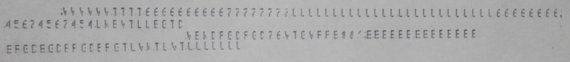
By inserting paper into the printer, I was able to check it, and he did print something, but this “something” was incorrect.
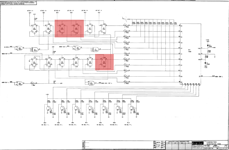
It seems that the last column of each character disappeared and, moreover, despite the keystrokes, only a limited set of characters appears on the paper. After checking with the ASCII table, you can see that two bits are stuck. Having traced these bits, we see that the correct values are supplied to the input of the symbol generator. Since the column counter is also located inside this generator, it becomes the main suspect. First you need to check the triggers marked in red.
It turned out that these chips are not working properly. Replace the broken 7474, produced by National Semiconductor (again NS!) In 1972, with ceramic from Fairchild and Texas Instruments.
Visible last character
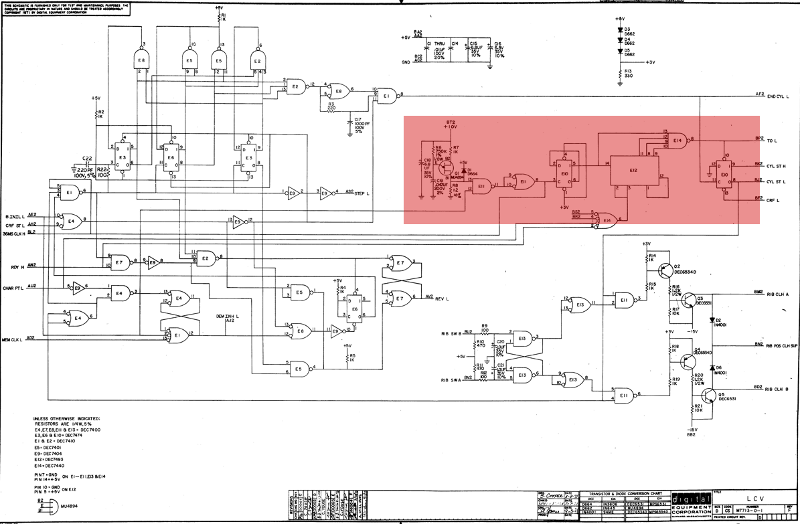
There is one more trouble. The function "visible last character" does not work for the first time until the machine is warmed up. It starts functioning some time after the start. This is a function that moves the printhead two characters to the right after a timeout of 1 second so that the print character can see the last character typed. Great stuff if you use the machine as a console terminal. I traced the problem to a dead 1 second timeout generator. Red area in the diagram.
Initially, it looked like a non-working E14 (7440), but when I tested it with the use of a cooling spray, it turned out that this E12 meter (7493) behaves badly. Again the NS chip! Replacing it with a chip from TI, released in 1969, I saw that the generator was working.
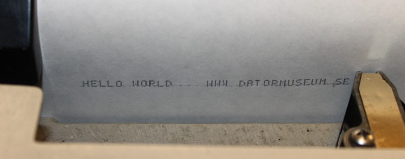
Works!
The last problem is connected with the fact that the stepping motor was stalled during the carriage transfer on the filled line. Step pulses were just too fast. The LA30 has a separate unit that controls acceleration during carriage transfer. I simply lowered the maximum speed by setting one of the potentiometers in the G936 module.
With this last edit, the printer is working as it should!
Source: https://habr.com/ru/post/243555/
All Articles