Recovery PDP 11/04. Tape station TU60
Continuation of the translation of the article on the restoration of one old interesting machine. In the first part, we adjusted the main board unit. Many heavy pictures. Italic my comments.
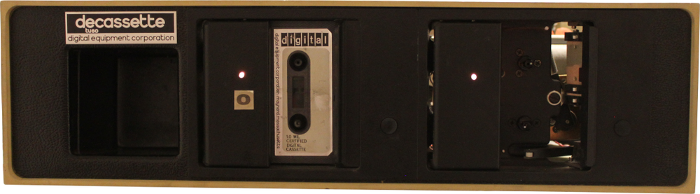
In the 70s, DEC created a simple replacement for punched tapes, which was based on a variety of simple audio cassettes. The TU60 accommodates two blocks of streamers. 50 meter tape could store up to 100Kb:
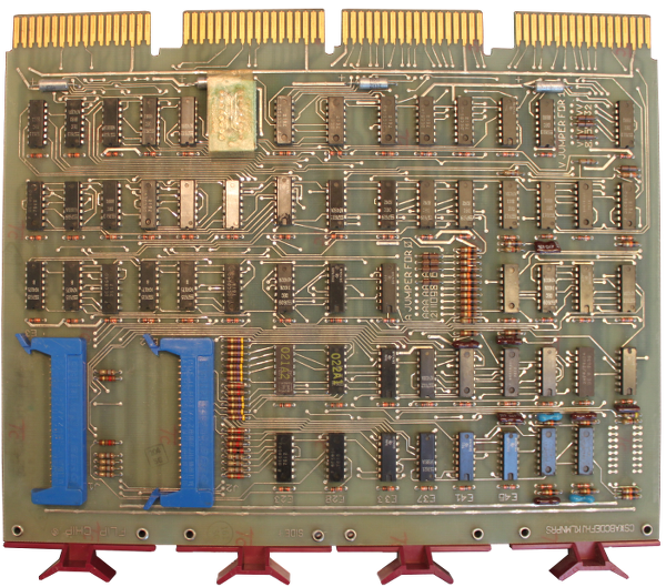
All the drive logic is contained in 2x six-contact boards ( I wrote about this earlier, unification is good ):
')
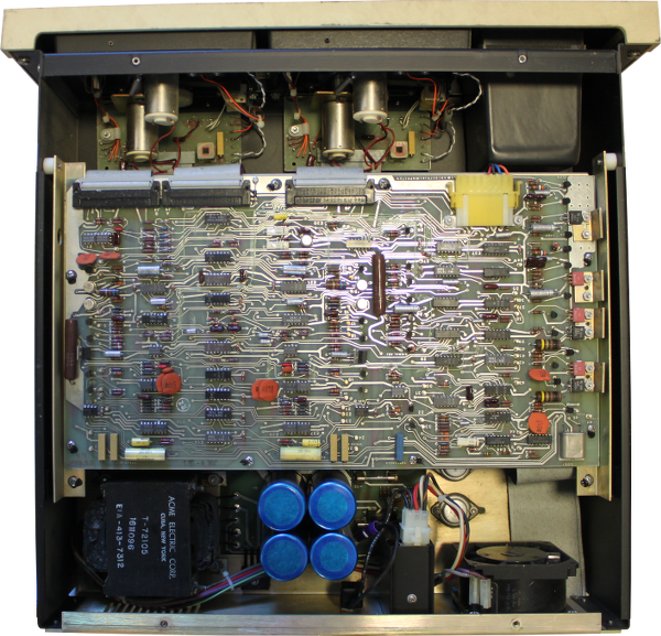
In the top view, you can see a board with analog logic, which controls the motors and reads data from the magnetic heads. Unlike conventional audio cassettes, the drives in the TU60 do not use a tension drum to control the speed of the tape passage. Instead, two independent motors are used. One to rewind the tape and to keep it in tension. The second one, controlled by servo, serves to pull the tape forward ( in fact, this is a hell of a scheme. When the cassette is played or just pauses, the first motor is also turned on. Let's say one of them tries to wind back 100 revolutions, and the second - forward at 110. And then the stronger wins, but, of course, the magnetic tape does not really like it, so it is not even recommended to keep this station turned on for a long time. ). The rotation speed of the second motor is constant ( not quite correctly stated, it is constant when reading the tape, but the server is the same! And the speed changes depending on the tasks. For example, when the tape is idle, this motor paired with the first, reverse, motor provides tension, there is its speed lower than during broaching ), the bitrate on the tape is also, so the information density varies throughout the length of the tape. The TU60 uses a Manchester code to encode the data.
The TA11 controller module is represented by the four-contact Unibus M7892 board ( I also wrote about the different names of one board in the last article ):
The controller provides a simple interface from two registers: command-status ( despite frequent practice, give the register for reading in one format and accept for writing in the other, everything is wrong here. This is a complete register, but in which some fields are read-only , the others are write-only, but there are also mixed read-write. ), available at 0177500, and a data buffer, located on 0177502. The board is not just an intermediary between TU60 and PDP-11, but also contains additional logic - a work circuit interrupt and address decoder (it is necessary to catch the reference to Regis frames).
When I started playing with this device, I immediately ran into a problem. The rewind button seemed to work fine. But then, suddenly, she broke down. It was clear that the triangular thing that connected the motor axis and the cassette fell from the axis. According to the drawings, there should be an installation screw # 2-56 1/8 "( inch size ). But it was not there! And it was not clear how he could disappear. The second drive had the same problem (this kind of installation screws is extremely difficult to find in Sweden, for we use the metric system.) I looked more closely at the scheme, and noticed “loctite” on the other lower triangular coupling instead of “set screw” ( Loctite produces glue and other chemistry ). Perhaps they just used Loctite for both linkages ? Anyway, I bought glue and, you know what, it worked. just great!
However, the Maindec ZTAA diagnostic test did not pass. The first problem I discovered was the DEC8881 driver located on the control board, which prevented the EOT and BOT signals from passing. I replaced it with 7439, which I bought in China for about $ 3 / piece. The interesting thing is that when I unsoldered the DEC8881, it was labeled 7439 below! After this, the diagnosis began to take place on the second streamer, but not on the first one. Broach forward did not work at all. Step by step, I tracked the faulty open collector driver 75452. Finally, both drives passed ZTAA. But not ZTAB ...
In order to find out what happens when writing data to a tape, I wrote a small program in assembler, which continuously wrote a sequence of bytes from 0 to 255 throughout the tape. The program worked, so I modified it the same way to read data from the tape. By connecting the logic analyzer to the data buffer, I received a constant stream of bytes 00, 01, 02, ... FD, FE, FF, 00, 01. Reading and writing worked!
I received images of tapes with the CAPS-11 operating system. The boot cassette contained the file CTLOAD.SYS, which provided the initial load of the CAPS-11 OS itself. Well, maybe the “operating system” is too loud, the CAPS-11 is a fairly simple command line parser with the functions of loading and saving files to a cassette. The system itself was in the CAPS11.S8K file, and was linked to work in an environment with 8 kilograms of memory ( memory in the PDP was measured in processor words. By the way, this was a good octal system that was used to set numbers, mainly addresses ) . . The boot process of this OS is quite complicated. The boot area (located at 01000) is called CBOOT. It skips the first 32 bytes of the CTLOAD.SYS file (which must be first on the tape). It then reads the next 128 bytes into memory at address 0. This part of CTLOAD.SYS is called PRELDR. PRELDR finds out the size of available memory and loads the entire CTLOAD.SYS into memory at the highest possible address. The unit to be loaded contains CABLDR and CBOOT (mirror). CABLDR is Cassette Absolute Loader, but, despite the name, the format of the files read is the same as for punched tapes. It follows that CAPS11.S8K has a punched tape format, and can be easily downloaded via PDP11GUI ( read about this program in the last article ). However, since CABLDR uses the switch register, which the programming console provides, to determine what and how to load ( in this register, for example, it was possible to set the system relocation address and load it to the user address ), and since I have no, CABLDR stops the machine with the exception of non-existent memory.
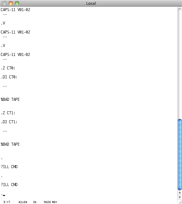
Using the PDP11GUI with a starting address of 021510, allows you to see the CAPS-11 prompt. The system from the beginning of the 70s was launched in 2014. 40 years:
Undoubtedly, the TU60 does not work very well.
In order to deal with the problem of TU60, it is necessary that this device could simply repeat the recorded sequence of operations in the desired order. Alas, the work with diagnostics in the XXDP is rather unpredictable. They can print the same error code for both read and write operations. At least I can’t pinpoint what’s going wrong. In addition, when using a logic analyzer, I can carry out the same measurements over and over again, only slightly changing the test points for research. I decided that the best way to move on is to write my own simple test program. Before that, I wrote a tiny assembler code that read and wrote data on tape. But even with a small increase in the amount of code, more and more effort was needed to debug, because I am not a very experienced assembler programmer for PDP-11. I love C.
What do you need to write C programs? Of course, the cross compiler! Page Diane Neisus inspired me. I downloaded Binutils 2.24 with GCC 4.8.2 and compiled them.
Binutils:
GCC:
Then I needed a file with an entry point for CRT - crt0.s. I just wrote a minimal version that worked:
Since the formatted line output is quite a useful thing, I looked for and found a tiny printf implementation for embedded development that completely satisfied me. Compiling the library and trying to link it, I received a packet of messages that many functions were not found - ___mulhi3, ___udivhi3 and others. Functions were used by gcc instead of the native instructions of the PDP-11 assembler. I had to write my own versions of these simple functions that performed multiplication, division, and taking the remainder.
Now, at compile time using the -m10 flag used to create a PDP-11/10 compatible output file, the compiler crashed while generating code to convert short to long. The only solution I found is to compile under the PDP-11/40 and then manually replace those instructions that are not supported by the PDP-11/04, like SXT or ASHC.
After that, I was ready to write a real Hello world:
I told the linker that I had to relocate the code to the address 0x1000 or 010000, and then I used objdump to convert the objektnik to a pure binary file.
At first I tried to run this file in the E11 emulator, before turning on the real hardware. But here is a screenshot of the launch via PDP11GUI on a real machine:
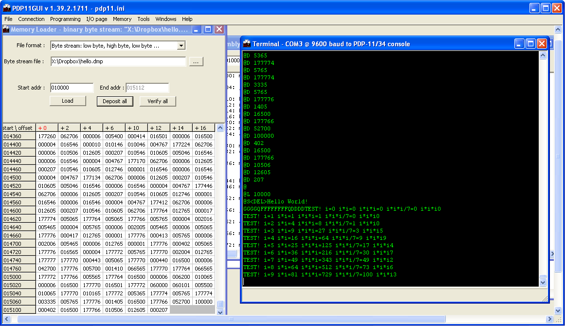
Excellent! Formatted output works as expected. Multiplication, division and taking the remainder also give the correct result (Well, in fact, not quite. It turned out that the function of taking the remainder contains a bug, which I had to fix). Now I had an easy way to write my own C test programs that would load my old TU60. In the end, I think I can write a program that reads files through the serial port and sends them to the TU60, thus creating boot cartridges. In any case, I have to patch CABLDR inside CTLOAD.SYS so that it does not try to read the switch register, which certainly results in an exception being thrown. (The machine does not have a programming console).
I spent a few hours writing a small program, which I called the TU60EXERCISER :

Now I can perform any operations on the drive in an easier way than using standard ZTA ** programs. Testing team READ revealed a problem on the driver with an open collector DEC8881 ( this is the next DEC8881, and not the one that was replaced earlier ), which I did not notice earlier when I connected the logic analyzer directly to the TU60 data buffer. The problem was that the CRC generation or, conversely, the CRC check failed. I always got a CRC error when reading the data, even when they were read correctly.
The TU60EXERCISER'a source can be found here .
Below are four photos showing what happens when we write “AB” characters to tape, and a 16-bit checksum is generated. The data LSB is written first, and the WRITED signal is set to the active-low level.
The clue is that the CRC is generated by a shift register with feedback from the input signal passing through the XOR gates for bits 15, 13 and 0.
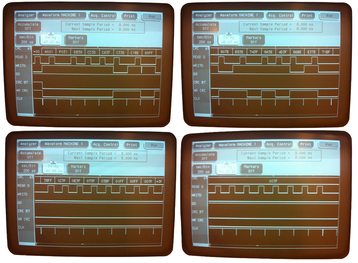
Is the error obvious? I did not immediately notice her, but after a few hours I studied the photo again and found it!
Bit 5 is stuck at a high level. But not always, as sharp-eyed comrades can correct me. At the beginning, all bits are zero. That's right, but the entire shift register is in a reset state due to the fact that it was given a clear signal ( at 8271, like many others, there is a state clearing pin ). In this case, the output is correct, but, when sequential data is entered into the shift register, it produces an incorrect result. He always moves one. The element is implemented by the Signetics N8271 chip, similar to Texas Instruments SN74179.
I ordered a new one from Bulgaria (!).
I had several failures. After I finally got 74179 from Bulgaria and soldered it, and my TU60EXERCISER program, with the appropriate emulator setup, tested in E11, the tapes began to fail. This was manifested in the fact that the friction between the head and the tape was so great that the streamer could not rewind them correctly. In addition, this led to a situation where the drive could not write or count anything due to the fact that the movement of the tape was intermittent.
It turned out that this is a common problem of old tapes. I did not have at hand Deoxit D5 (a special lubricant for electro-mechanical connections, used in the article by reference ). I tried the CRC silicone spray, but it did not give any noticeable effect.
Therefore, you need to look for new tapes. I tried to convert standard audio tapes with a soldering iron. In some way it worked, but for some reason it was sometimes not detected that the rewind reached the beginning of the tape. The streamer just kept rewinding at high speed.
But then I, nevertheless, found a guy with Ebay from Germany, who sold me 10 Verbatim cassettes from a thermopolymer for 1 euro each.
When they arrived, I immediately rushed to test them, but it turned out that the computer no longer gives me the command line of the console emulator. What happened? Having connected the logic analyzer, I found that the machine stops after trying to execute the instruction “mov” on the 83rd line.
Connecting the probes to the micro address bus showed that, after the sampling step, the processor jumps to the micro instruction at address 60 instead of 62 (source mode 2 handler ( when decoding the instructions, there are 8 operand addressing modes, a la register, the immediate value, etc. For some reason, mode 0 was considered here, instead of mode 2. The mode itself is encoded directly in the instructions. )). It seems that the E88 does not work, as its output is always 1, regardless of the input. But it is possible that there is also a problem with the E77, since it controls the micro address bus. In any case, I have neither 7427 nor 74H01. A fellow collector from Sweden sent me 7427 for verification.
But, while this chip is on the way, I can use a spare processor board for testing, so as not to waste time.
I started checking new cassettes using ZTAA diagnostics, which went perfectly well. Then I launched ZTAB, which should also be successful, since I fixed the CRC check. I started the test and left for half an hour. When I returned, the sound made by the streamer was different, unusual, and the console was full of endless heaps of errors. The second drive rotated very slowly. It turned out that rubber or plastic on the spindle turned into some amorphous glue.
I was looking for any replacement for this elastic band, but I could not find anything that would fit snoop-snoop. I tried two layers of bicycle tire chamber. I was not sure that this type of rubber is soft enough. But, in any case, I had to use good glue in order to glue the rubber on the spindle wheel, because the gum on the bad glue quickly flew off. The second problem was that the thickness of the bicycle chamber was not constant over the entire cut circle. It may or may not interfere. Let's see.
I went and asked the plumbers if they had anything suitable, but, unfortunately, they could not help me.
By the way, at that moment I received 7427 to replace the chip in the E88 position, and the processor was working! Through the Swedish electronics forum, I contacted the person who sent me a spindle gum. I was able to remove the old one and paste a new one on the super glue.
Now the majority of diagnostics pass on both drives, with the exception of ZTAE, which doesn’t check anything special?
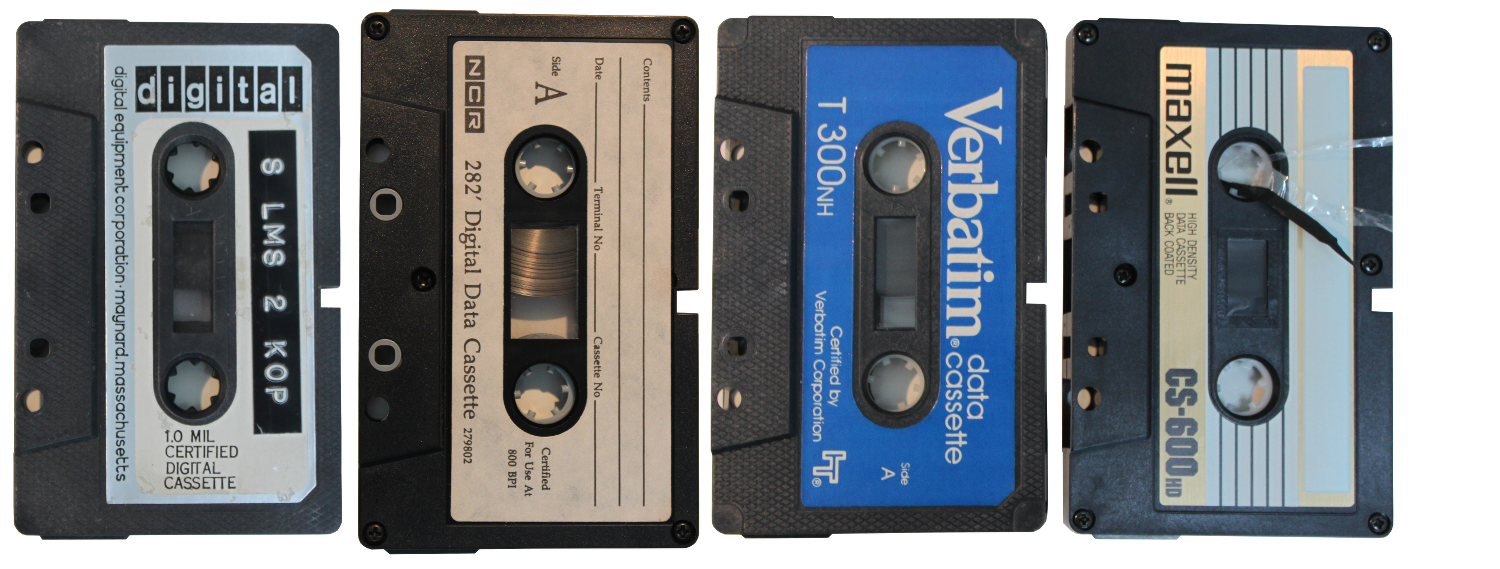
The next question was to choose the right carrier. I only had 2 original tapes from DEC. Later I got some NCR tapes from a guy from Morocco. Apparently, they were stored in the desert for a long time, because all the grease evaporated. Verbatim cassettes from a guy from Germany look pretty good. Although I had problems with a pressure device made from something like foam, which wears out over time. Finally, I have Maxell cassettes that fail almost continuously. It seems that the tape can not withstand the tension created by the drive, it breaks after just a few rewinds ( which, by the way, I wrote about earlier ).
I also tried to convert ordinary audio cassettes, but with varying success. Some worked, some did not.
The next step is to record CAPS-11 on the tape and run it! Just need a little refinement TU60EXERCISER .
After several rounds of debugging TU60EXERCISER (now renamed to 60tools), I finally got the option that allowed me to write data to tape. Now, I wonder if the PDP-11 will load from the cassette?
After typing "CT" in the console emulator, the tape drive first wrapped the tape for a short moment, but then just stopped. I began to reread the manual for CAPS-11 and noticed the following:
Does PRELDR rely on the fact that CBOOT, judging by the scheme, is located at 01000? I, of course, boot from the PROM.
EDIT: The real source of the problem is found thanks to a collector-friend: CBOOT places the TA11 CSR ( command-and-status register of the tape drive controller ) in R0 ( user processor register ), while the M9312 CT ( M9312 is a console emulator, CT is the command of this emulator, but At the same time, this is the name of the EPROM chip, which contains the boot code from the tape. The command only runs the code of this EPROM, but it automatically tries to boot even when the system starts. ) When loaded, it inserts TA11 CSR in R1 (and the number of the tape measure in R0). PRELDR expects to see precisely in R0 the value of register TA11. I have to patch PRELDR so that it can boot directly from the CT-ROM.
I used E11 to build CBOOT from sources and wrote the result in the CBOOT.BIN file. After that, I loaded it into memory via pdp11gui and ran it from the address 01000. Yes! The tape began to play for about half a minute, and then a single "." Appeared. I launched CAPS-11!
My program, for writing to tape, did not write the closing file, which should be the last on the tape. However, it worked and so! CTLOAP.SYS is the patched version of CTLOAD.SYS, from which all references to the switch register have been removed so that the program can work on machines only with the operator console.
For starters, I patched CTLOAD.SYS to boot directly from the CT EPROM to the M9312, which is extremely convenient. No more swearing when typing commands or when uploading a file ( 9600bps, sadly it all ) boot loader. Just turn on the INIT toggle switch and the streamer starts working. Fine. It turned out that not only PRELDR needs to be modified, but we also need to add the BR instruction ( unconditional short transition, -128 .. + 127 ) in order to skip the initialization of the R0 register in the depths of CABLDR. Here is the patched version, if anyone needs it.
After downloading the CAPS-11, I was interested in what is actually stored on those two old DEC cassettes. Photos of one of them are above, it is marked as “S LMS 2 KOP”. “KOP” may mean “KOPIA”, COPY. But besides that, I can't make out what the other characters mean. It contains some files:
In the CAPS-11 system, the cassette is dated January 1975. Files almost 40 years old. I made a copy and used my patched bootloader to run it. She started. But there was no command line. It is possible that the software was configured for a different version of hardware, different from mine.
It would be interesting to extract the contents of the cassette. I continued to work on tu60tools . Again, long debugging when running on bare metal. There are no nice stack traces when there is a problem with pointers. Finally, the TU60read was ready to read files from a cassette, and, it seems, even worked. At the very least, she correctly read the file that I recorded on the tape. I used it for a copy cassette made earlier and received the following files:
CTLOAD.SYS
CAPS11.S8K
PIP.SRU
EDIT.SLG
LINK.SRU
ODT.SLG
PAL.SRU
BASIC.LDA
I studied the CTLOAD.SYS binary. It occupies 896 bytes (7 blocks) instead of 1024. But it looks full. Disassembling shows that most of the code is identical to CTLOAD.SYS, coming with CAPS-11.
BASIC.LDA is like a copy of a punched tape with BASIC. Running strings over this binary, I got “PDP-11 BASIC, VERSION 007A”. Similarly, for "CAPS11.S8K" gives "CAPS-11 V01-02". Therefore, I think that this tape is only slightly different from the original.
After that, I tried to do the same study of the second tape, but the file system on it was damaged. I managed to dig out only this piece of code for the PDP-8:
Okay. Now that the machine is running as it should, I will begin the final stage of this PDP-11 recovery project: revitalize the LA30 Decwriter and launch it in conjunction with the PDP-11.
In the third part of the article, we repair the LA30 Decwriter terminal.
Streamer TU60 and controller TA11
In the 70s, DEC created a simple replacement for punched tapes, which was based on a variety of simple audio cassettes. The TU60 accommodates two blocks of streamers. 50 meter tape could store up to 100Kb:
All the drive logic is contained in 2x six-contact boards ( I wrote about this earlier, unification is good ):
')
In the top view, you can see a board with analog logic, which controls the motors and reads data from the magnetic heads. Unlike conventional audio cassettes, the drives in the TU60 do not use a tension drum to control the speed of the tape passage. Instead, two independent motors are used. One to rewind the tape and to keep it in tension. The second one, controlled by servo, serves to pull the tape forward ( in fact, this is a hell of a scheme. When the cassette is played or just pauses, the first motor is also turned on. Let's say one of them tries to wind back 100 revolutions, and the second - forward at 110. And then the stronger wins, but, of course, the magnetic tape does not really like it, so it is not even recommended to keep this station turned on for a long time. ). The rotation speed of the second motor is constant ( not quite correctly stated, it is constant when reading the tape, but the server is the same! And the speed changes depending on the tasks. For example, when the tape is idle, this motor paired with the first, reverse, motor provides tension, there is its speed lower than during broaching ), the bitrate on the tape is also, so the information density varies throughout the length of the tape. The TU60 uses a Manchester code to encode the data.
The TA11 controller module is represented by the four-contact Unibus M7892 board ( I also wrote about the different names of one board in the last article ):
The controller provides a simple interface from two registers: command-status ( despite frequent practice, give the register for reading in one format and accept for writing in the other, everything is wrong here. This is a complete register, but in which some fields are read-only , the others are write-only, but there are also mixed read-write. ), available at 0177500, and a data buffer, located on 0177502. The board is not just an intermediary between TU60 and PDP-11, but also contains additional logic - a work circuit interrupt and address decoder (it is necessary to catch the reference to Regis frames).
When I started playing with this device, I immediately ran into a problem. The rewind button seemed to work fine. But then, suddenly, she broke down. It was clear that the triangular thing that connected the motor axis and the cassette fell from the axis. According to the drawings, there should be an installation screw # 2-56 1/8 "( inch size ). But it was not there! And it was not clear how he could disappear. The second drive had the same problem (this kind of installation screws is extremely difficult to find in Sweden, for we use the metric system.) I looked more closely at the scheme, and noticed “loctite” on the other lower triangular coupling instead of “set screw” ( Loctite produces glue and other chemistry ). Perhaps they just used Loctite for both linkages ? Anyway, I bought glue and, you know what, it worked. just great!
However, the Maindec ZTAA diagnostic test did not pass. The first problem I discovered was the DEC8881 driver located on the control board, which prevented the EOT and BOT signals from passing. I replaced it with 7439, which I bought in China for about $ 3 / piece. The interesting thing is that when I unsoldered the DEC8881, it was labeled 7439 below! After this, the diagnosis began to take place on the second streamer, but not on the first one. Broach forward did not work at all. Step by step, I tracked the faulty open collector driver 75452. Finally, both drives passed ZTAA. But not ZTAB ...
In order to find out what happens when writing data to a tape, I wrote a small program in assembler, which continuously wrote a sequence of bytes from 0 to 255 throughout the tape. The program worked, so I modified it the same way to read data from the tape. By connecting the logic analyzer to the data buffer, I received a constant stream of bytes 00, 01, 02, ... FD, FE, FF, 00, 01. Reading and writing worked!
Launch CAPS-11
I received images of tapes with the CAPS-11 operating system. The boot cassette contained the file CTLOAD.SYS, which provided the initial load of the CAPS-11 OS itself. Well, maybe the “operating system” is too loud, the CAPS-11 is a fairly simple command line parser with the functions of loading and saving files to a cassette. The system itself was in the CAPS11.S8K file, and was linked to work in an environment with 8 kilograms of memory ( memory in the PDP was measured in processor words. By the way, this was a good octal system that was used to set numbers, mainly addresses ) . . The boot process of this OS is quite complicated. The boot area (located at 01000) is called CBOOT. It skips the first 32 bytes of the CTLOAD.SYS file (which must be first on the tape). It then reads the next 128 bytes into memory at address 0. This part of CTLOAD.SYS is called PRELDR. PRELDR finds out the size of available memory and loads the entire CTLOAD.SYS into memory at the highest possible address. The unit to be loaded contains CABLDR and CBOOT (mirror). CABLDR is Cassette Absolute Loader, but, despite the name, the format of the files read is the same as for punched tapes. It follows that CAPS11.S8K has a punched tape format, and can be easily downloaded via PDP11GUI ( read about this program in the last article ). However, since CABLDR uses the switch register, which the programming console provides, to determine what and how to load ( in this register, for example, it was possible to set the system relocation address and load it to the user address ), and since I have no, CABLDR stops the machine with the exception of non-existent memory.
Using the PDP11GUI with a starting address of 021510, allows you to see the CAPS-11 prompt. The system from the beginning of the 70s was launched in 2014. 40 years:
Undoubtedly, the TU60 does not work very well.
Running C-code on a bare system
In order to deal with the problem of TU60, it is necessary that this device could simply repeat the recorded sequence of operations in the desired order. Alas, the work with diagnostics in the XXDP is rather unpredictable. They can print the same error code for both read and write operations. At least I can’t pinpoint what’s going wrong. In addition, when using a logic analyzer, I can carry out the same measurements over and over again, only slightly changing the test points for research. I decided that the best way to move on is to write my own simple test program. Before that, I wrote a tiny assembler code that read and wrote data on tape. But even with a small increase in the amount of code, more and more effort was needed to debug, because I am not a very experienced assembler programmer for PDP-11. I love C.
What do you need to write C programs? Of course, the cross compiler! Page Diane Neisus inspired me. I downloaded Binutils 2.24 with GCC 4.8.2 and compiled them.
Binutils:
src/configure --target=pdp11-aout --disable-nls make all sudo make install GCC:
src/configure --target=pdp11-aout --disable-nls --without-headers --enable-languages=c make all-gcc sudo make install-gcc Then I needed a file with an entry point for CRT - crt0.s. I just wrote a minimal version that worked:
.text .globl _main, ___main, _start _start: mov $400,sp jsr pc, _main halt ___main: rts pc Since the formatted line output is quite a useful thing, I looked for and found a tiny printf implementation for embedded development that completely satisfied me. Compiling the library and trying to link it, I received a packet of messages that many functions were not found - ___mulhi3, ___udivhi3 and others. Functions were used by gcc instead of the native instructions of the PDP-11 assembler. I had to write my own versions of these simple functions that performed multiplication, division, and taking the remainder.
Now, at compile time using the -m10 flag used to create a PDP-11/10 compatible output file, the compiler crashed while generating code to convert short to long. The only solution I found is to compile under the PDP-11/40 and then manually replace those instructions that are not supported by the PDP-11/04, like SXT or ASHC.
After that, I was ready to write a real Hello world:
pdp11-aout-gcc -m10 -Ttext 1000 -msoft-float -nostartfiles -nodefaultlibs -nostdlib crt0.s printf.c test.c divmulmod.s pdp11-aout-objcopy -O binary a.out hello.dmp I told the linker that I had to relocate the code to the address 0x1000 or 010000, and then I used objdump to convert the objektnik to a pure binary file.
At first I tried to run this file in the E11 emulator, before turning on the real hardware. But here is a screenshot of the launch via PDP11GUI on a real machine:
Excellent! Formatted output works as expected. Multiplication, division and taking the remainder also give the correct result (Well, in fact, not quite. It turned out that the function of taking the remainder contains a bug, which I had to fix). Now I had an easy way to write my own C test programs that would load my old TU60. In the end, I think I can write a program that reads files through the serial port and sends them to the TU60, thus creating boot cartridges. In any case, I have to patch CABLDR inside CTLOAD.SYS so that it does not try to read the switch register, which certainly results in an exception being thrown. (The machine does not have a programming console).
TU60EXERCISER
I spent a few hours writing a small program, which I called the TU60EXERCISER :
Now I can perform any operations on the drive in an easier way than using standard ZTA ** programs. Testing team READ revealed a problem on the driver with an open collector DEC8881 ( this is the next DEC8881, and not the one that was replaced earlier ), which I did not notice earlier when I connected the logic analyzer directly to the TU60 data buffer. The problem was that the CRC generation or, conversely, the CRC check failed. I always got a CRC error when reading the data, even when they were read correctly.
The TU60EXERCISER'a source can be found here .
Search for errors in the logic of working with CRC
Below are four photos showing what happens when we write “AB” characters to tape, and a 16-bit checksum is generated. The data LSB is written first, and the WRITED signal is set to the active-low level.
The clue is that the CRC is generated by a shift register with feedback from the input signal passing through the XOR gates for bits 15, 13 and 0.
Is the error obvious? I did not immediately notice her, but after a few hours I studied the photo again and found it!
Bit 5 is stuck at a high level. But not always, as sharp-eyed comrades can correct me. At the beginning, all bits are zero. That's right, but the entire shift register is in a reset state due to the fact that it was given a clear signal ( at 8271, like many others, there is a state clearing pin ). In this case, the output is correct, but, when sequential data is entered into the shift register, it produces an incorrect result. He always moves one. The element is implemented by the Signetics N8271 chip, similar to Texas Instruments SN74179.
I ordered a new one from Bulgaria (!).
One step forward and two (three?) Back
I had several failures. After I finally got 74179 from Bulgaria and soldered it, and my TU60EXERCISER program, with the appropriate emulator setup, tested in E11, the tapes began to fail. This was manifested in the fact that the friction between the head and the tape was so great that the streamer could not rewind them correctly. In addition, this led to a situation where the drive could not write or count anything due to the fact that the movement of the tape was intermittent.
It turned out that this is a common problem of old tapes. I did not have at hand Deoxit D5 (a special lubricant for electro-mechanical connections, used in the article by reference ). I tried the CRC silicone spray, but it did not give any noticeable effect.
Therefore, you need to look for new tapes. I tried to convert standard audio tapes with a soldering iron. In some way it worked, but for some reason it was sometimes not detected that the rewind reached the beginning of the tape. The streamer just kept rewinding at high speed.
But then I, nevertheless, found a guy with Ebay from Germany, who sold me 10 Verbatim cassettes from a thermopolymer for 1 euro each.
When they arrived, I immediately rushed to test them, but it turned out that the computer no longer gives me the command line of the console emulator. What happened? Having connected the logic analyzer, I found that the machine stops after trying to execute the instruction “mov” on the 83rd line.
77 165046 005503 adc r3 ; R3=000000 C=1 78 165050 000303 swab r3 ; R3=000000 C=0 79 165052 001377 bne . ; br . if FAIL 80 81 ; ----------------------------------------- 82 83 165054 012702 165000 T2: mov #data0,r2 ; R2=165000 84 165060 011203 mov (r2),r3 ; R2=165000 R3=165000 Connecting the probes to the micro address bus showed that, after the sampling step, the processor jumps to the micro instruction at address 60 instead of 62 (source mode 2 handler ( when decoding the instructions, there are 8 operand addressing modes, a la register, the immediate value, etc. For some reason, mode 0 was considered here, instead of mode 2. The mode itself is encoded directly in the instructions. )). It seems that the E88 does not work, as its output is always 1, regardless of the input. But it is possible that there is also a problem with the E77, since it controls the micro address bus. In any case, I have neither 7427 nor 74H01. A fellow collector from Sweden sent me 7427 for verification.
But, while this chip is on the way, I can use a spare processor board for testing, so as not to waste time.
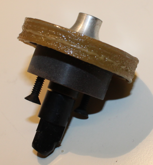
I started checking new cassettes using ZTAA diagnostics, which went perfectly well. Then I launched ZTAB, which should also be successful, since I fixed the CRC check. I started the test and left for half an hour. When I returned, the sound made by the streamer was different, unusual, and the console was full of endless heaps of errors. The second drive rotated very slowly. It turned out that rubber or plastic on the spindle turned into some amorphous glue.
I was looking for any replacement for this elastic band, but I could not find anything that would fit snoop-snoop. I tried two layers of bicycle tire chamber. I was not sure that this type of rubber is soft enough. But, in any case, I had to use good glue in order to glue the rubber on the spindle wheel, because the gum on the bad glue quickly flew off. The second problem was that the thickness of the bicycle chamber was not constant over the entire cut circle. It may or may not interfere. Let's see.
I went and asked the plumbers if they had anything suitable, but, unfortunately, they could not help me.
New rubber pad on the spindle
By the way, at that moment I received 7427 to replace the chip in the E88 position, and the processor was working! Through the Swedish electronics forum, I contacted the person who sent me a spindle gum. I was able to remove the old one and paste a new one on the super glue.
Now the majority of diagnostics pass on both drives, with the exception of ZTAE, which doesn’t check anything special?
Hidden text
@ 007574 006574 006774 170617 @DD CLEARING MEMORY CHMDDA0 XXDP+ DD MONITOR 8K BOOTED VIA UNIT 0 ENTER DATE (DD-MMM-YY): RESTART ADDR:033726 50 HZ? NY LSI? N THIS IS XXDP+. TYPE "H" OR "H/L" FOR DETAILS .D ENTRY# FILNAM.EXT DATE LENGTH START 000001 HMDDA1.SYS 22-MAR-80 17 000050 000002 HDDDA1.SYS 22-MAR-80 3 000071 000003 HUDIA0.SYS 22-MAR-80 6 000074 000004 UPD1 .BIN 22-MAR-80 12 000102 000005 UPD2 .BIN 22-MAR-80 16 000116 000006 HELP .TXT 22-MAR-80 26 000136 000007 HSAAA0.SYS 22-MAR-80 24 000170 000010 SETUP .BIN 22-MAR-80 26 000220 000011 GKAAA0.BIC 1-MAR-89 14 000252 000012 GKABC0.BIC 1-MAR-89 15 000270 000013 ZTAAC0.BIN 11-AUG-76 16 000307 000014 ZTABC0.BIN 11-AUG-76 17 000327 000015 ZTACC0.BIN 11-AUG-76 13 000350 000016 ZTADC0.BIN 11-AUG-76 16 000365 000017 ZTAEB0.BIN 11-AUG-76 13 000405 000020 ZTAFC0.BIN 11-AUG-76 2 000422 000021 ZTAHA0.BIN 11-AUG-76 6 000424 000022 ZKLAE0.BIC 11-AUG-76 14 000432 000023 ZDLAF1.BIN 12-MAR-77 17 000450 000024 ZDLBB0.BIN 11-AUG-76 16 000471 000025 ZDLCA0.BIC 11-AUG-76 19 000511 000026 ZDLDA1.BIC 29-JAN-77 19 000534 000027 ZDLOC0.BIN 17-AUG-76 4 000557 000030 ZKWKA1.BIC 29-JAN-77 27 000563 .R ZTABC0 MAINDEC-11-DZTAB-C SWR = 000000 NEW = TESTING DRIVE A | END PASS TESTING DRIVE B ` END PASS TESTING DRIVE A ` DATA PROBLEM PC TACS EXPECT RCV'D 010470 000004 000377 000122 x END PASS TESTING DRIVE B ` END PASS TESTING DRIVE A ` 000000 177500 001056 016632 @DD CLEARING MEMORY CHMDDA0 XXDP+ DD MONITOR 8K BOOTED VIA UNIT 0 ENTER DATE (DD-MMM-YY): RESTART ADDR:033726 50 HZ? NY LSI? N THIS IS XXDP+. TYPE "H" OR "H/L" FOR DETAILS .R ZTAEB0 MAINDEC-11-DZTAE-B SWR = 000000 NEW = DRIVE A AND DRIVE B WILL BE TESTED *** FORMAT *** DRIVE A 001612 000000 001056 011646 @DD CLEARING MEMORY CHMDDA0 XXDP+ DD MONITOR 8K BOOTED VIA UNIT 0 ENTER DATE (DD-MMM-YY): RESTART ADDR:033726 50 HZ? NY LSI? N THIS IS XXDP+. TYPE "H" OR "H/L" FOR DETAILS .R ZTADC0 MAINDEC-11-DZTAD-C SWR = 000000 NEW = TESTING DRIVE A AND DRIVE B WRITE-FILE-GAP IMPROPER FLAG OCCURRED TEST ERROR PC PC TACS TADB 005636 010562 120140 000017 END PASS TESTING DRIVE B AND DRIVE A READ SHORT RECORD TEST ERROR BYTES PC PC TACS TADB LEFT 004742 011204 140144 000350 000006 BUFFER COMPARE BAD DATA READ TEST ERROR EXPT'D RCV'D BYTE PC PC TACS DATA DATA NUMBER 004746 010512 140144 000314 000357 000001 END PASS TESTING DRIVE A AND DRIVE B END PASS TESTING DRIVE B AND DRIVE A END PASS TESTING DRIVE A AND DRIVE B END PASS TESTING DRIVE B AND DRIVE A END PASS TESTING DRIVE A AND DRIVE B END PASS TESTING DRIVE B AND DRIVE A The next question was to choose the right carrier. I only had 2 original tapes from DEC. Later I got some NCR tapes from a guy from Morocco. Apparently, they were stored in the desert for a long time, because all the grease evaporated. Verbatim cassettes from a guy from Germany look pretty good. Although I had problems with a pressure device made from something like foam, which wears out over time. Finally, I have Maxell cassettes that fail almost continuously. It seems that the tape can not withstand the tension created by the drive, it breaks after just a few rewinds ( which, by the way, I wrote about earlier ).
I also tried to convert ordinary audio cassettes, but with varying success. Some worked, some did not.
The next step is to record CAPS-11 on the tape and run it! Just need a little refinement TU60EXERCISER .
Finally loading from the cassette
After several rounds of debugging TU60EXERCISER (now renamed to 60tools), I finally got the option that allowed me to write data to tape. Now, I wonder if the PDP-11 will load from the cassette?
After typing "CT" in the console emulator, the tape drive first wrapped the tape for a short moment, but then just stopped. I began to reread the manual for CAPS-11 and noticed the following:
PRELDR should be the first entry in the first file on the system tape. This preloader is a small program written in accordance with the “CBOOT Loader Format”, which is sufficiently advanced to determine the size of the memory and load subsequent programs into the upper memory addresses. CBOOT links, loads into memory at address 0 and starts it automatically. CAPS-11, at this stage of loading, is depicted in Figure E-3 as Memory Map # 2.
Does PRELDR rely on the fact that CBOOT, judging by the scheme, is located at 01000? I, of course, boot from the PROM.
EDIT: The real source of the problem is found thanks to a collector-friend: CBOOT places the TA11 CSR ( command-and-status register of the tape drive controller ) in R0 ( user processor register ), while the M9312 CT ( M9312 is a console emulator, CT is the command of this emulator, but At the same time, this is the name of the EPROM chip, which contains the boot code from the tape. The command only runs the code of this EPROM, but it automatically tries to boot even when the system starts. ) When loaded, it inserts TA11 CSR in R1 (and the number of the tape measure in R0). PRELDR expects to see precisely in R0 the value of register TA11. I have to patch PRELDR so that it can boot directly from the CT-ROM.
I used E11 to build CBOOT from sources and wrote the result in the CBOOT.BIN file. After that, I loaded it into memory via pdp11gui and ran it from the address 01000. Yes! The tape began to play for about half a minute, and then a single "." Appeared. I launched CAPS-11!
.DI -- CTLOAP SYS 19-FEB-14 CAPS11 S8K 25-NOV-13 DEMO PAL 25-NOV-13 EDIT SLG 25-NOV-13 LINK SRU 25-NOV-13 ODT SLG 25-NOV-13 PAL SRU 25-NOV-13 PIP SRU 25-NOV-13 ?NO SENTINEL FILE ?SYNTAX ERROR . My program, for writing to tape, did not write the closing file, which should be the last on the tape. However, it worked and so! CTLOAP.SYS is the patched version of CTLOAD.SYS, from which all references to the switch register have been removed so that the program can work on machines only with the operator console.
Archeology of old cassettes
For starters, I patched CTLOAD.SYS to boot directly from the CT EPROM to the M9312, which is extremely convenient. No more swearing when typing commands or when uploading a file ( 9600bps, sadly it all ) boot loader. Just turn on the INIT toggle switch and the streamer starts working. Fine. It turned out that not only PRELDR needs to be modified, but we also need to add the BR instruction ( unconditional short transition, -128 .. + 127 ) in order to skip the initialization of the R0 register in the depths of CABLDR. Here is the patched version, if anyone needs it.
After downloading the CAPS-11, I was interested in what is actually stored on those two old DEC cassettes. Photos of one of them are above, it is marked as “S LMS 2 KOP”. “KOP” may mean “KOPIA”, COPY. But besides that, I can't make out what the other characters mean. It contains some files:
010000 051415 177714 000002 @CT CAPS-11 V01-02 .DA 27-MAR-14 .DI CT1: 27-MAR-14 CTLOAD SYS 07-JAN-75 CAPS11 S8K 07-JAN-75 PIP SRU 07-JAN-75 EDIT SLG 07-JAN-75 LINK SRU 07-JAN-75 ODT SLG 07-JAN-75 PAL SRU 07-JAN-75 BASIC LDA 07-JAN-75 . In the CAPS-11 system, the cassette is dated January 1975. Files almost 40 years old. I made a copy and used my patched bootloader to run it. She started. But there was no command line. It is possible that the software was configured for a different version of hardware, different from mine.
It would be interesting to extract the contents of the cassette. I continued to work on tu60tools . Again, long debugging when running on bare metal. There are no nice stack traces when there is a problem with pointers. Finally, the TU60read was ready to read files from a cassette, and, it seems, even worked. At the very least, she correctly read the file that I recorded on the tape. I used it for a copy cassette made earlier and received the following files:
CTLOAD.SYS
CAPS11.S8K
PIP.SRU
EDIT.SLG
LINK.SRU
ODT.SLG
PAL.SRU
BASIC.LDA
I studied the CTLOAD.SYS binary. It occupies 896 bytes (7 blocks) instead of 1024. But it looks full. Disassembling shows that most of the code is identical to CTLOAD.SYS, coming with CAPS-11.
BASIC.LDA is like a copy of a punched tape with BASIC. Running strings over this binary, I got “PDP-11 BASIC, VERSION 007A”. Similarly, for "CAPS11.S8K" gives "CAPS-11 V01-02". Therefore, I think that this tape is only slightly different from the original.
After that, I tried to do the same study of the second tape, but the file system on it was damaged. I managed to dig out only this piece of code for the PDP-8:
Hidden text
TO +1 IF HIGH TEST DCA TEST TAD TABNO AND P777 DCA TABNO /SAVE TABLE NUMBER TAD LTAB DCA TCORE /SET CORE ADDRESS CLL CIF JMS I TABLE /READ LIMIT TABLES TABNO, 0 TCORE, 0 CLA CLL CDF TAD I BAND1 /FETCH NUMBER OF DCA B1 /CHANNELS FROM MEM0 TAD I BAND2 DCA B2 JMS I RSETDF IAC JMS COMWRD /FETCH BATCH TRAIN NO SPA CLA /RELOCATE OUTER BAND? JMP INNER /NO - INNER DCA CHNO /YES - SET 1:ST CHANNEL NUMBER TAD B1 /FETCH CHANNEL COUNTER JMP BOTH INNER, TAD B1 /CALCULATE FIRST CHANNEL NO CIA DCA CHNO TAD B2 /FETCH CHANNEL COUNTER BOTH, DCA CHCNT /SAVE COUNTER ON PAGE ZERO TAD P5 JMS COMWRD /FETCH CHANNEL NUMBER SNA /ZERO? JMP ALL /YES - TEST ALL ON ONE BAND TAD M1 /NO - SAVE CORRECT DCA CHNO /CHANNELNUMBER TAD M1 DCA CHCNT /SET COUNTER TO -1 SKP SINGLE, CLA IAC /SET AC TO 11 ALL, TAD P10 /SET AC TO 10 JMP I RELO /RELOCATE ACLEAR, DCA I TEMP /CLEAR RCLEAR IN COMMAND BUFFER ISZ TADDR /SET POINTER TO CORRECT CDF /ADD TERM IN TBTAB DCA I TADDR /ZERO ADD TERM JMS I RSETDF /RESET DATA FIELD NOP CMA DCA QCPFEL JMS I DCWAIT TAD QCP /INDICATE READY CIF CLL JMS I MONDSC /RETURN TO QCP HLT /SECURITY HALT COMWRD, 0 /ADD TERM IN AC TAD COMAND DCA TEMP /ADDR IN COMAND BUFFER TAD I TEMP /FETCH COMAND WORD JMP I COMWRD /TO AC AND RETURN /CONSTANTS: BAND1, 66 /PAGE0, MEM0 BAND2, 67 / " " B1, 0 B2, 0 TEMP, 0 P3, 3 P4, 4 P5, 5 P10, 10 P50, 50 P51, 51 P52, 52 P54, 54 P55, 55 P77, 77 P777, 777 P3777, 3777 P6000, 6000 M1, -1 M2, -2 M2001D, -3721 QCP, 4023 /AUT OSTART QCP $ Okay. Now that the machine is running as it should, I will begin the final stage of this PDP-11 recovery project: revitalize the LA30 Decwriter and launch it in conjunction with the PDP-11.
In the third part of the article, we repair the LA30 Decwriter terminal.
Source: https://habr.com/ru/post/243553/
All Articles