Repair of a loop of LEGO NXT
 The article describes one of the possible ways to make handicraft of the graphite LCD loop of the LEGO Mindstorms NXT control unit. Addressed to those who are no longer helped by laying folded pieces of paper, rubber bands, or a magical act with warming up capacitors on the board of control buttons (some complicated magic, I could not understand what its sacred meaning is).
Also, the article may be useful to those who have stopped working screen favorite calculator, remote control car alarm, sewing machine and other devices, repair of which in specialized workshops for some reason is impossible or impractical. Written by non-professionals for non-professionals, publicly available materials and tools will be used for repairs. Carefully, in the text of the article a lot of large photos of mediocre quality.
Required resources
- breadboard knife;
- scissors;
- tweezers;
- tripod "third hand" with a lens;
- small soldering iron or soldering station;
- non-flushing flux;
- conductive adhesive;
- epoxy adhesive;
- double sided tape;
- masking tape;
- thin wire;
- wooden toothpicks;
- cotton buds;
- ethanol.
Prologue
A congenital problem of the control block of the LEGO Mindstorms NXT designers of the first releases was a graphite cable. Judging by the number of articles devoted to replacing or restoring articles, similar trains have helped pass the time with a soldering iron in the hands of more than one evening to the owners of some models of cars, sewing machines, calculators, synthesizers and other equipment. The failure of such a loop in the LEGO NXT control unit is a matter of time rather than intensity of use. At least, I once had to face such a problem with the designer, who just lay packed for several years after purchase.
Outwardly, it looks like this: after switching on the unit, you hear the start melody, pressing the control buttons is also accompanied by sounds, when connected to a computer, the unit is normally detected by the system, you can add your own programs or upgrade the firmware through the LEGO NXT software. But it does not work built-in LCD.
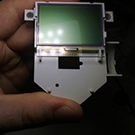
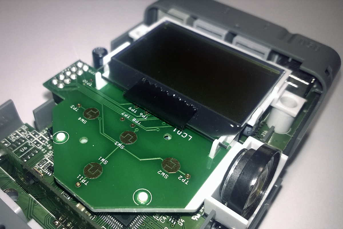
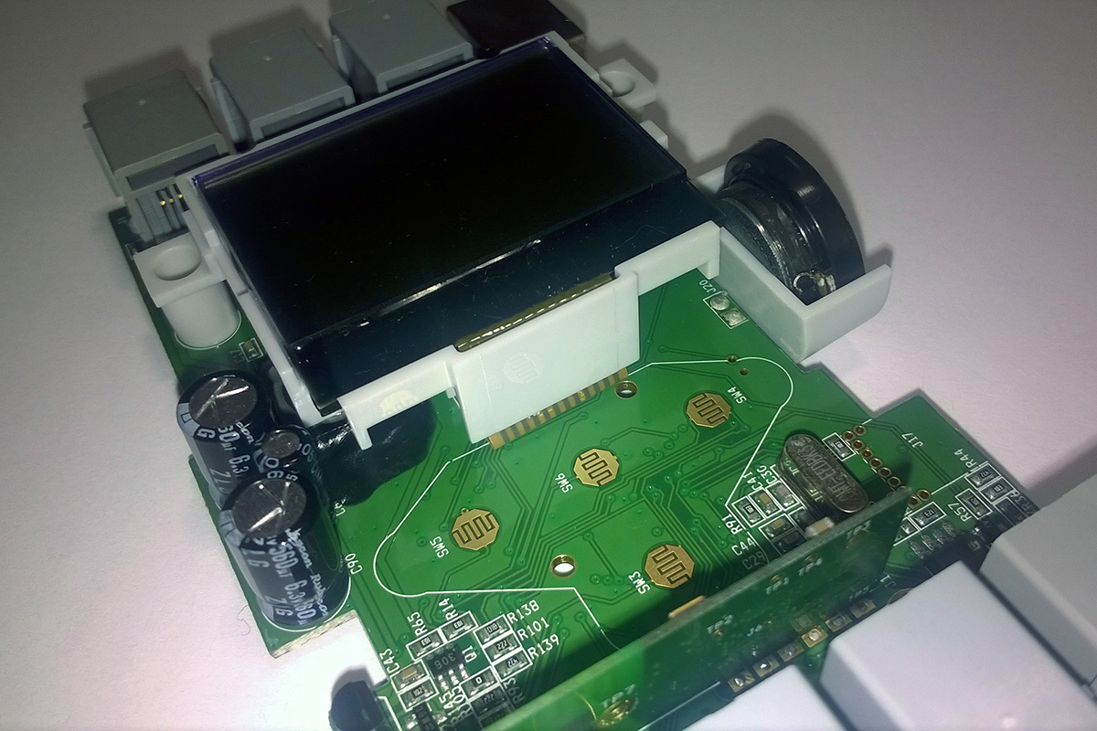
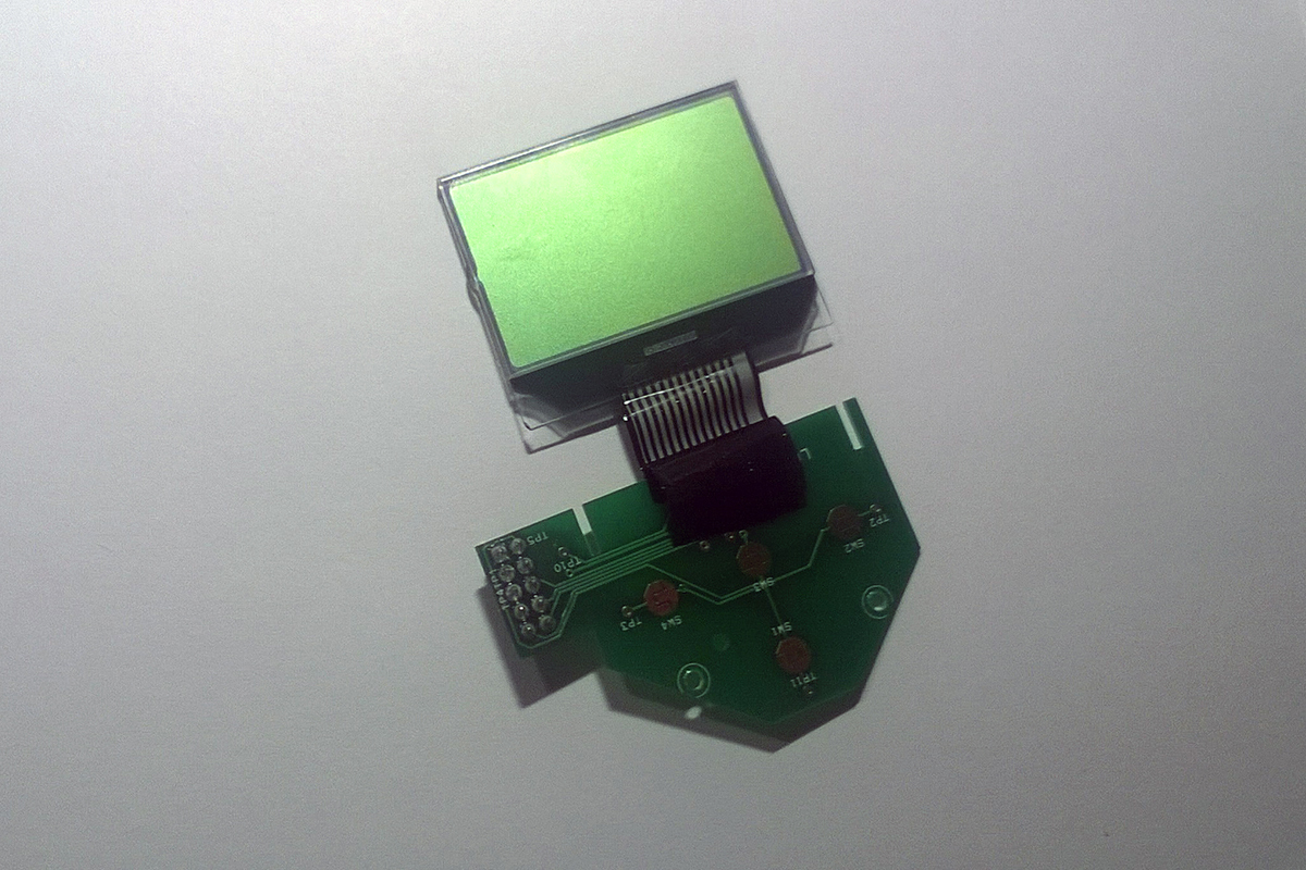
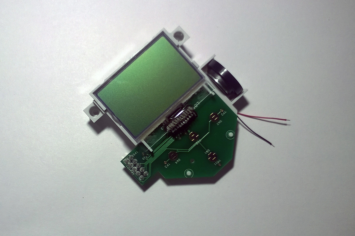
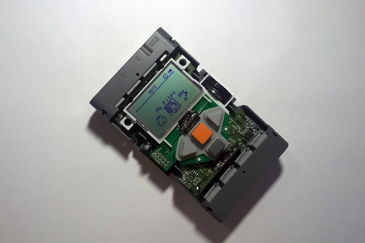
We must pay tribute to LEGO, after a couple of years they reworked the control unit board, replacing the graphite cable with a copper one, at the same time transferring the contact pads of the control buttons to the main board. This made it possible to abandon the additional charge for buttons and simplified the design, adding reliability to it. Externally, the blocks are almost indistinguishable. You can quickly find out who is in front of us by unscrewing the four screws in the battery compartment and removing the cover from the unit. In the first and second photographs there is a block with a graphite cable, in the third - its more “happy” fellow with copper.
')
If your unit has the same cable as the first two photos, you can first try to iron it in the places of contact with a heated soldering iron through a folded paper sheet twice or three times. Proceed carefully, the glass screen - may burst. Such warming up can help, sometimes long enough. If it does not help, you will have to repair the cable. For repair, you need to remove the LCD together with the control button board, the speaker and the plastic base. Twisting out two more screws, and wiring to the dynamics of the board, you can unsolder or just bite off. They are still short, for convenience, it is better to replace them with longer ones.
Outwardly, it looks like this: after switching on the unit, you hear the start melody, pressing the control buttons is also accompanied by sounds, when connected to a computer, the unit is normally detected by the system, you can add your own programs or upgrade the firmware through the LEGO NXT software. But it does not work built-in LCD.
We must pay tribute to LEGO, after a couple of years they reworked the control unit board, replacing the graphite cable with a copper one, at the same time transferring the contact pads of the control buttons to the main board. This made it possible to abandon the additional charge for buttons and simplified the design, adding reliability to it. Externally, the blocks are almost indistinguishable. You can quickly find out who is in front of us by unscrewing the four screws in the battery compartment and removing the cover from the unit. In the first and second photographs there is a block with a graphite cable, in the third - its more “happy” fellow with copper.
')
View photos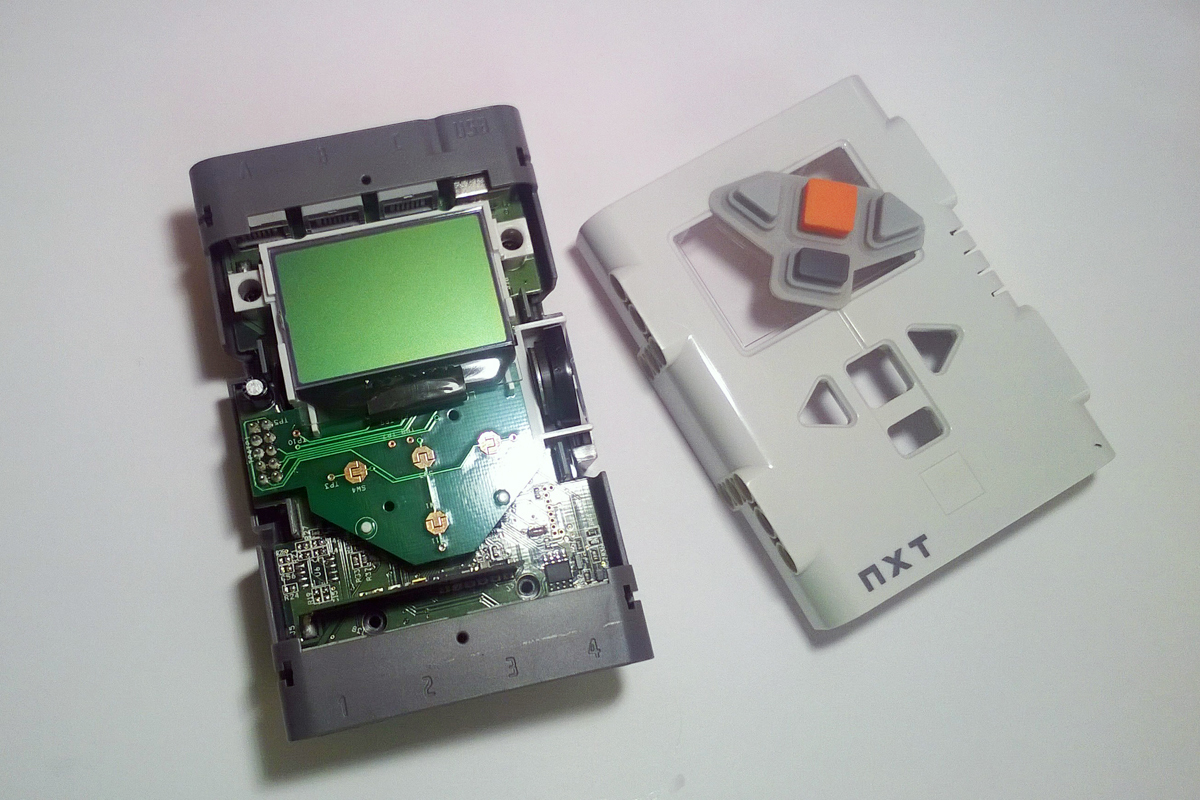
If your unit has the same cable as the first two photos, you can first try to iron it in the places of contact with a heated soldering iron through a folded paper sheet twice or three times. Proceed carefully, the glass screen - may burst. Such warming up can help, sometimes long enough. If it does not help, you will have to repair the cable. For repair, you need to remove the LCD together with the control button board, the speaker and the plastic base. Twisting out two more screws, and wiring to the dynamics of the board, you can unsolder or just bite off. They are still short, for convenience, it is better to replace them with longer ones.
Formulation of the problem
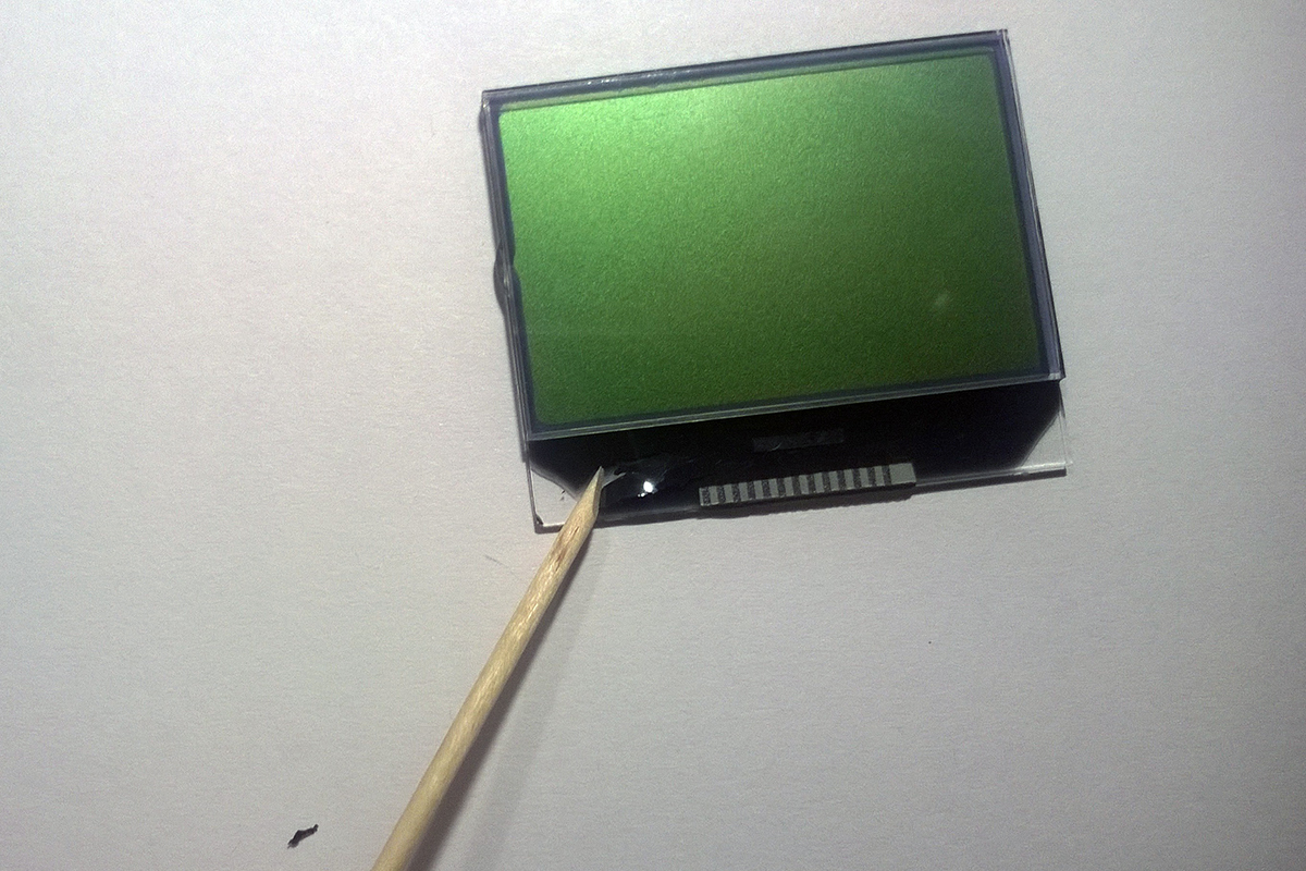
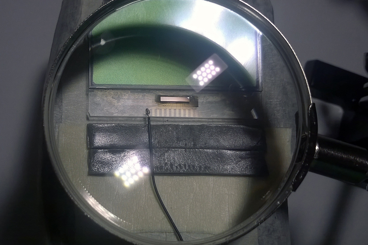
Our goal is to create a conductive connection between the pads on the LCD glass and the wiring, which we will replace the defective cable. Contact pads on the glass can be seen by placing the LCD at a certain angle to the light source. Just put it on your palm and try to gently shake in different directions under the light of a desk lamp.
View photos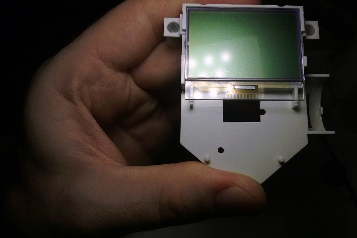
Preparation of the bridgehead
So, the hero of the occasion lies in front of us on the table. Podkovyrivaem board control buttons and remove it from the plastic base. LCD is glued to the base with two strips of double-sided tape. Remembering that the screen is glass , do not exert excessive effort. We drip the inner side of the LCD with five or six drops of alcohol, let it flow into the gap between the base and the LCD and spread along the scotch tape and, slightly pulling the LCD off the base, carefully peel it off. The adhesive tape on the basis of change is not worth it, after the evaporation of alcohol, it will not lose its adhesive properties.
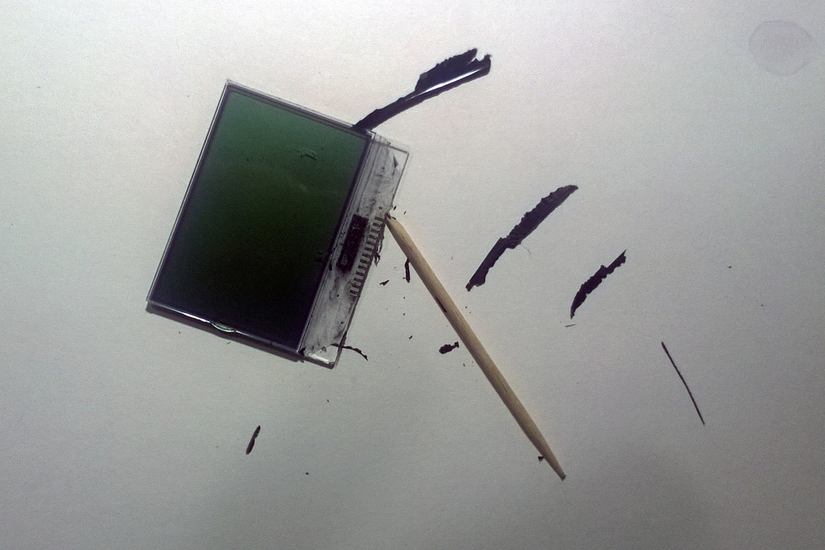
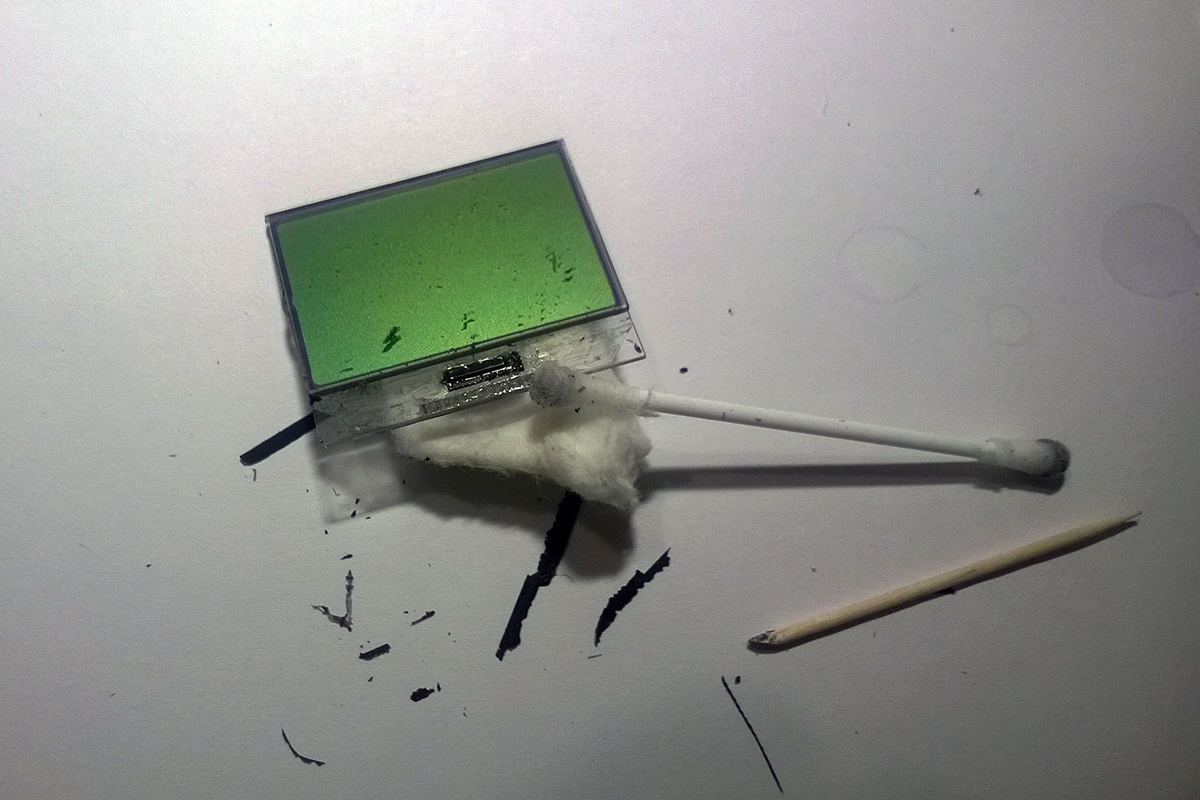
Similarly, peel off the speaker from the base so as not to burn it when replacing wires. The speaker is glued to the base through the gasket, when peeling off we try to keep the gasket on the speaker, and the tape on the base. We help them sharpened in the form of a blade with a toothpick.
With the same toothpick we hook on a black protective tape, and rip it off from both sides of the cable. Behind an adhesive tape we hook up and we tear off a loop. Since we decided to replace the cable with thin mounting wires, it is possible not to stand on ceremony with it. If you still want to keep it for history, you can try to remove the protective tape from it, gradually soaking it with alcohol.
After removing the old cable with toothpicks, cotton swabs and alcohol sharpened with a spatula, we clean the contact pads on the LCD and the board. Cleaning the glass will require some time and effort. The remains of the silicone compound around the pads are removed quite hard, and they need to be cleaned well. Attention, do not use for cleaning metal objects and liquids more aggressive than alcohol . The contact pads on the glass are very thin, and the surface of the screen is covered with a layer of plastic.
After the cleaning is completed, you can fix the LCD with double-sided tape on some basis for the convenience of further work.
View photos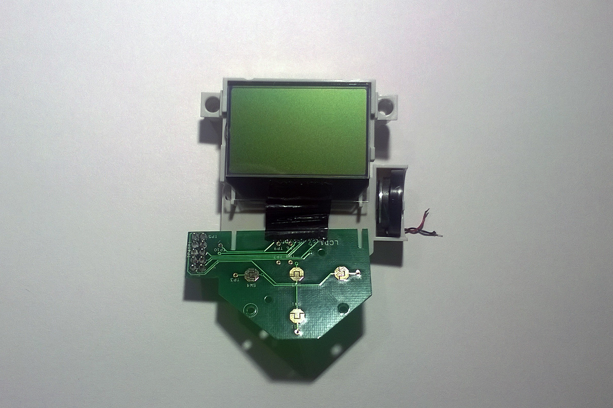


Climax
Bearing in mind how the advertising articles are related to Habré, I still have to note that I managed to more or less tolerably paste the wiring with only a specific adhesive from a specific manufacturer. What kind of glue can be viewed on the first photo of this section. At the end of the article I will try to explain what inspired me to write it and justify the choice of glue.
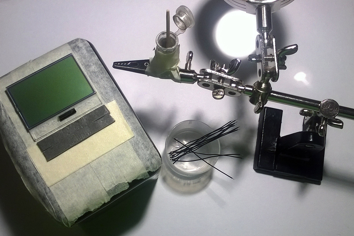
So, our test subject is secured with double-sided tape on a suitable basis, about two millimeters from him are glued strips of double-sided tape for temporary fixation of the wires. The wiring itself is neatly cleaned and trimmed on both sides, then placed in a suitable container with alcohol.
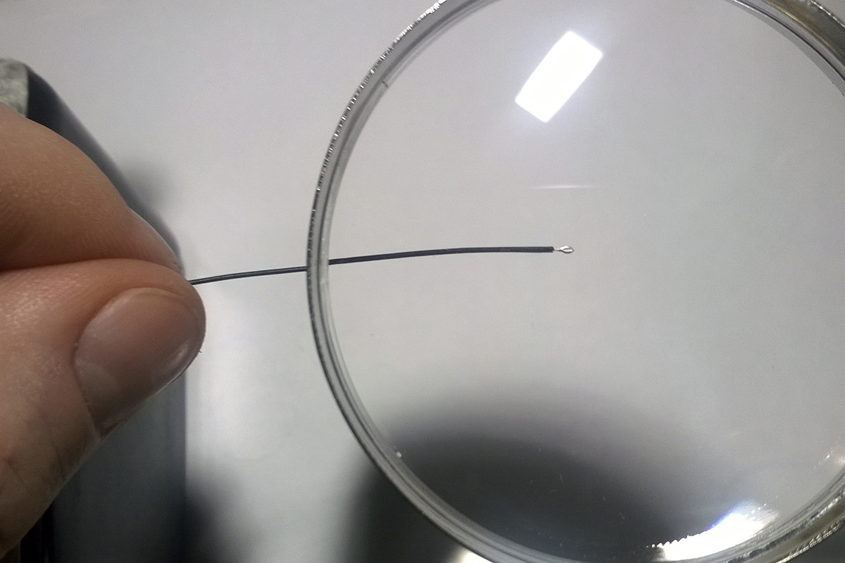
The basic idea is to pick up one or two drops of carefully mixed conductive glue on a toothpick and, holding it vertically above the vial of glue, substitute the exposed tip and cut to the desired length under the flowing from the toothpick. Gently turning the wire, you must achieve the formation of a drop of glue on it. Similar to the one on which you can look at the third photo of this section. It is necessary to act quickly, because the glue thickens quickly enough . Therefore, as soon as possible after applying the adhesive postings need to cling to the contact area on the glass. Approximately as shown in the fourth photo section.
If you do everything quickly enough, the glue on the tip of the wire does not have time to thicken much and wets the pad well. For the correct distribution of glue it is useful to make one or two movements with a tip wiring along the contact pad. After a successful docking, the wiring and the contact area for the complete success of the wiring is fixed on the double-sided tape pasted next to the LCD. And if it didn’t work out, it doesn’t matter - the wiring is returned with the end soiled with glue into the container with alcohol, the glue remains from the glass are cleaned with a toothpick, after which the operation is repeated the necessary number of times.
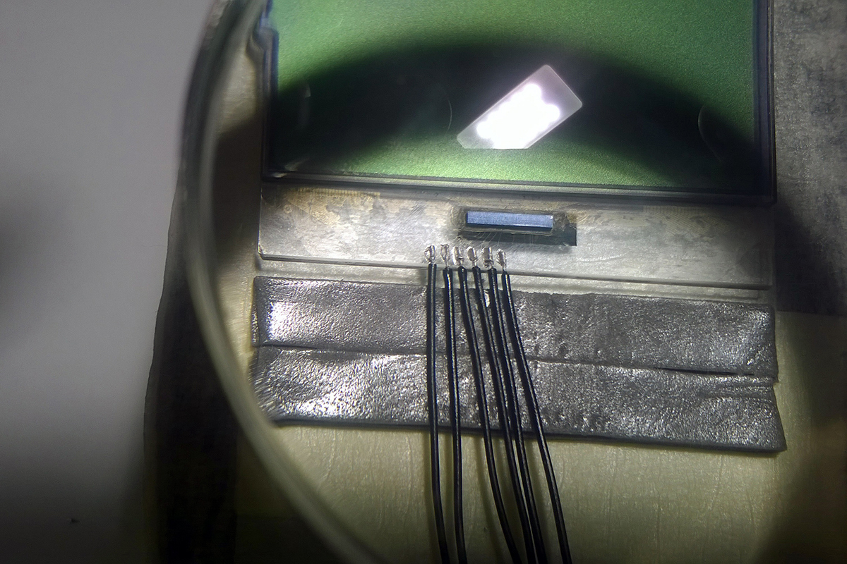
After the last posting has been stuck victoriously on its contact pad and fixed on the adhesive tape, wait half an hour for the glue to set. Now you can carefully install an additional retainer for the wires, I used in this quality a piece of plastic that was broken when unpacking the syringe with epoxy resin.
Well, the moment of truth comes. We serve contact pads on the board of control buttons and, acting as carefully as possible, solder the free ends of the wiring to them. We connect everything to the main board, after inserting five batteries into the battery compartment. Insert the sixth battery, watching the LCD. We try not to break the wires, if everything works. Remember that the strength of the compound in conductive glue is almost none.
We consolidate the success of applying a layer of epoxy to the glued wiring. During this procedure, we try not to touch any wires or glass. You can wait until a small drop of epoxy collected on it will drain from the toothpick, touch this drop on the first wire and start to stretch it, trying to pull it down to the twelfth. If there is not enough epoxy, we recruit a new batch and continue from the point of rupture. We are waiting for the full setting of epoxy resin.
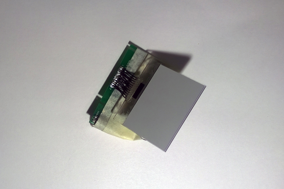
Everything, the most difficult behind. If necessary, we align the wiring, add another layer of epoxy on the front side, wait for its setting, detach and turn over the LCD, glue the back side with epoxy.
View photos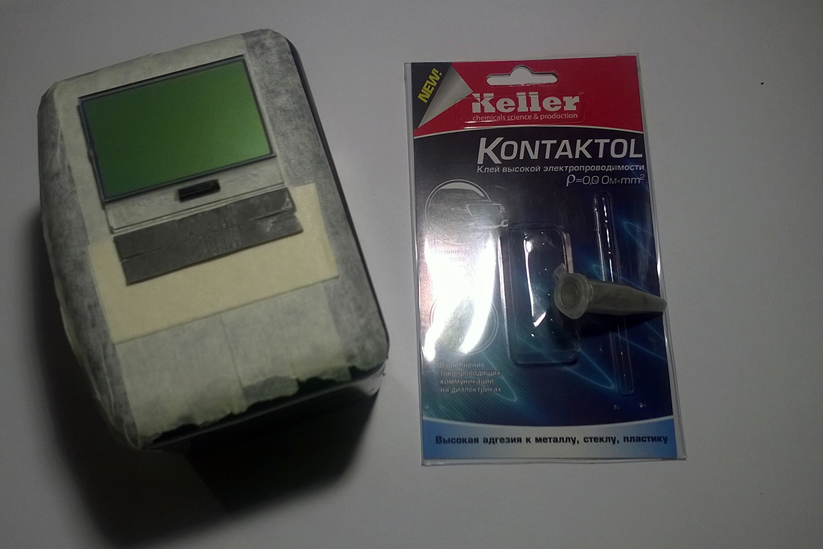


Final stage
Carefully measuring everything, align and trim to the required length glued to the LCD wiring. Carefully clean and fix the ends of the wiring and, folding the LCD and the board of the control buttons on the front sides, solder the wiring to the pre-tinned contact pads of the board. When soldering use no washout flux.
Flush out excess flux with alcohol, install the reunited board and the LCD on the base. It is more convenient to first install the board, and then, gently bending the wires to glue to the base of the LCD. Do not forget to replace the wiring, we return to the place of the speaker and buttons.
Solder the wires from the speaker to your places, install the repaired unit on the main board. Twist the two screws, fill the battery compartment with batteries. Having heard the starting melody, we are convinced of the LCD operability.
View photos
Source: https://habr.com/ru/post/243501/
All Articles