Electronic Cake in your pocket: development diary
About a year ago, when I was playing with the official Arduino Starter Kit , I had the idea to make a “circuit cake” as a gift for my wife, namely, a board with LED candles that can be blown out. This task seemed to me a good educational project for understanding how to program microcontrollers and how to implement programs into matter (after all, I began to get involved in electronics relatively recently, and started programming at school, so I felt a huge gap in my education).
I would like to share my experience of developing such a simple device from scratch, and at the same time lay out its scheme and program, so that you can reproduce it at home.
Story
The first prototype was made on Arduino Uno and the piezo element attached to it as a candle blowing detector:
')
Reading the voltage on the piezo-element, the device was expecting the slightest change in readings. But even at the maximum resolution of the ADC, it was necessary to blow very well so that the candles began to fade. But they were extinguished well: at first they began to flicker with a different frequency and phase, and then in turn they were extinguished depending on the given random lifetime of each candle.
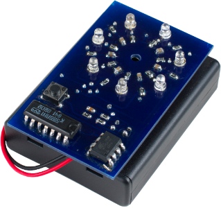
The next step I decided to make the cake more elegantly than a board with protruding wires. And I also wanted to show my wife that the cake works from a small microcontroller. Somewhere on the Internet, I found an article that the Arduino can be run on an ATTiny85 controller, I decided to use it as a brain. The problem was that this controller has only five general purpose legs that could be used for candles and a sensor, so it turned out that I could only use four candles if I put each LED on a separate leg. I did not know about charliplexing at that time, and decided to duplicate the candles with a delay circuit on the inverter: when the LEDs are flashing, it is unlikely that anyone will notice that they are duplicated with a phase delay. In addition, the additional elements fit well into the circular pattern of placement of candles:
I used four AAA batteries as power, which disrupted the brevity of the appearance. In addition, I wanted more honest candles and greater sensitivity. I rustled according to the specifications of the ATTiny series microcontrollers , and found an excellent analogue - ATTiny84 with 11 common legs of general purpose. In addition, it has an ADC input with a differential amplifier 20 times! So a new prototype appeared:
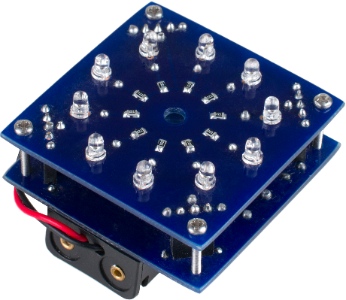
I was hoping to shove two AAA batteries between floors, but miscalculated with the size of the racks and the piezo-element, which should not fit close to the board, so I had to stick the batteries under the board. As the signal was amplified, the cake became much more sensitive, and noise appeared, so I needed to change the algorithm: I measured the standard deviation of the signal and turned on the blowing logic when this deviation exceeded some empirically found threshold. The program turned out to be small, less than 4 KB, so I took ATTiny44 , which has half the memory.
I didn’t like the power of the circuit and the empty space between the floors, I rummaged about the specifications of the batteries and found that there are AAAA batteries. They are quite small and provide a current of hundreds of milliamps. They are difficult to buy, but if you take a type 9LR61 nine-volt batteries, they inside consist of six AAAA batteries!
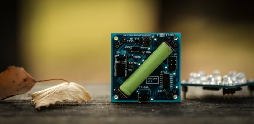
I also found an interesting HT7750 switching power supply microcircuit , which increases the supply voltage to +5 V by increasing the battery current, and decided to make a cake of such a size that one AAAA battery fit diagonally, which will power it. This is the result of this prototype:

The use of wide-angle LEDs not only improved the aesthetics of the cake, but also increased the viewing angle. I ordered the boards in China, which improved the quality of the finished device. But what I did not expect, so it is a sharp increase in noise when determining blowing. The fact is that the switching power supply itself is noisy, and here also the dependence of the output voltage on the current when a different number of LEDs is lit. The old algorithm stopped working, and I had to approach the task more thoroughly: read the readings from the piezo-sensor onto the computer and analyze the amplitude-frequency characteristic of the signal. I recorded one minute of silence, one minute of blowing and a minute of rustling friction against the hull. It turned out that the piezo-element has a resonance of about 1 kHz, by which one can quite reliably determine that the candles are now being blown out.
So, to determine the moment of blowing out the candles, I began to consider the fast Fourier transform with a Hanning window for a frequency of 1 kHz. ATTiny44 does not have a built-in multiplication command, and the memory is very limited (256 bytes of RAM, 4 KB per program), because all multiplications had to be replaced with shifts and additions, and in general, to significantly optimize the program so that everything fits. As a result of the program change, the cake exceeded all other prototypes in sensitivity. Then I began to remove the extra components in the signal path, which I naively considered a high-pass filter, and the cake began to react even better. Replacing the HT7750 with the HT7733 , i.e. replacing the output from +5 V to +3.3 V, I got a more economical use of the battery.
The last thing that confused me was that the power supply in off mode consumed approximately 17 µA, which meant emptying the battery in a year. But I remembered that this microcircuit has one version in the SOT-25 package, in which there is a permissive input, and made a small switch-on circuit, which, when the reset button was pressed, charged the capacitor to supply a high level at the permissive chip input with subsequent slow discharge within three minutes through a ten megohm resistor. After this timeout, the cake is turned off and begins to consume less than 1 µA, which is comparable to the self-discharge current of the battery.

Schematic diagram

The HT7733 is a switching power supply that increases the input supply voltage to +3.3 V. The 20-mm piezo element is connected to the differential AD converter of the microcontroller with a gain of 20 times. Each LED is connected to one leg of the microcontroller.
When you press the RESET, a transistor is opened, through which a 10 μF capacitor is charged and a high level is applied to the enable input of the power supply chip. The microcircuit turns on and starts producing a +3.3 V output for three minutes while the 10 μF capacitor discharges through a ten megohm resistor.
Program
C ++ program for Arduino IDE
///////////////////////////////////////////////////////////////////////////////////////////////// // BitCake v1.1.1 / November 8, 2014 // by Maksym Ganenko <buratin.barabanus at Google Mail> ///////////////////////////////////////////////////////////////////////////////////////////////// #include <avr/interrupt.h> #include <avr/pgmspace.h> #include <avr/power.h> #include <avr/sleep.h> #include <time.h> #include <util/delay.h> ///////////////////////////////////////////////////////////////////////////////////////////////// // set fixed delta loop time in milliseconds // 0 to use internal timer const uint8_t DELTA_LOOP_TIME_MS = 14; // amplify intermediate values to get better calculation accuracy const uint8_t SAMPLES_GAIN_ORDER = 5; // x32 const uint8_t RESULT_GAIN_ORDER = 2; // x4 // LEDs encoded by ports ID const prog_int8_t LEDS[] PROGMEM = { 0xA6, 0xA7, 0xB2, 0xB1, 0xB0, 0xA2, 0xA3, 0xA4, 0xA5 }; const uint8_t LEDS_NUM = sizeof(LEDS) / sizeof(LEDS[0]); // ADMUX register code for ADC const uint8_t PIEZO_ADMUX = 0b10101001; // Vref = 1.1V, (A1 - A0) x 20 // MCU prescaler const uint8_t MCU_PRESCALER = 0b000; // 1 => 8 Mhz CPU clock // ADC prescaler const uint8_t ADC_PRESCALER = 0b100; // 16 => 512 kHz ADC clock => 38.5k reads per sec // number of piezo reads to average per sample (for noise reduction) const uint8_t SUBSAMPLE_BUF_ORDER = 4; // => 16 const uint8_t SUBSAMPLE_BUF_SIZE = (1 << SUBSAMPLE_BUF_ORDER); // FFT samples number - can't be changed without changing FFT calculation code const uint8_t SAMPLE_BUF_ORDER = 5; // => 32 const uint8_t SAMPLE_BUF_SIZE = (1 << SAMPLE_BUF_ORDER); // FFT signal threshold to activate blowing logic // this value defines the sensitivity of device // depends on electronic components noise const uint8_t BLOWING_THRESHOLD = 3; // timeouts in milliseconds const uint32_t SETUP_TIME_MS = 750; // timeout before activating of cake logic const uint32_t DELAY_BLOWING_MS = 0; // delay LEDs flickering when blowing detected const uint32_t PROLONG_BLOWING_MS = 150; // prolong blowing logic when no blowing detected const uint32_t NO_ACTIVITY_MS = 60000; // turn off cake if no blowing detected const uint32_t TIME_LIMIT_MS = 150000; // time limit for cake to work // LEDs blinking periods when blowing logic is activated const uint8_t LEDS_PERIOD_MIN_MS = 100; const uint8_t LEDS_PERIOD_MAX_MS = 150; // LEDs time-to-live timeouts const uint16_t LEDS_TTL_MIN_MS = 200; const uint16_t LEDS_TTL_MAX_MS = 1000; ///////////////////////////////////////////////////////////////////////////////////////////////// volatile uint8_t samplePos = SAMPLE_BUF_SIZE; // FFT10 specific accumulators int16_t sampleAccA [5]; int16_t sampleAccB [5]; // LEDs state variables uint16_t ledsActivity; uint8_t ledsPeriod [LEDS_NUM]; uint8_t ledsPhase [LEDS_NUM]; uint8_t ledsTTL [LEDS_NUM]; // blowing logic state uint8_t blowing = false; uint32_t lastBlowingTime = 0; int16_t totalBlowingTime = 0; uint32_t globalTime = 0; uint32_t lastLoopTime; uint32_t setupPhaseTime; // for compatibility with other Atmel MCUs uint8_t portA, portB, portC, portD; ///////////////////////////////////////////////////////////////////////////////////////////////// // fast distance approximation uint32_t approxDist(int32_t dx, int32_t dy) { uint32_t min, max; if (dx < 0) dx = -dx; if (dy < 0) dy = -dy; if (dx < dy) { min = dx; max = dy; } else { min = dy; max = dx; } // coefficients equivalent to (123/128 * max) and (51/128 * min) return (((max << 8) + (max << 3) - (max << 4) - (max << 1) + (min << 7) - (min << 5) + (min << 3) - (min << 1)) >> 8); } const uint8_t FFT_DIVIDER_ORDER = 8; // => 256 // approximate multiplication int32_t mul256(int32_t x) { return x << 8; } int32_t mul240(int32_t x) { return (x << 8) - (x << 4); } int32_t mul208(int32_t x) { return (x << 7) + (x << 6) + (x << 4); } int32_t mul176(int32_t x) { return (x << 7) + (x << 5) + (x << 4); } int32_t mul144(int32_t x) { return (x << 7) + (x << 4); } int32_t mul96(int32_t x) { return (x << 6) + (x << 5); } int32_t mul48(int32_t x) { return (x << 5) + (x << 4); } typedef int32_t (*fmul32)(int32_t); const fmul32 fmulVec[4] = { mul96, mul176, mul240, mul256 }; // calculate FFT[10] for 32 samples uint8_t fft10() { int32_t a = 0; for (uint8_t i = 0; i < 4; ++i) { a += fmulVec[i](sampleAccA[i + 1]); } int32_t b = 0; for (uint8_t i = 0; i < 4; ++i) { b += fmulVec[i](sampleAccB[i + 1]); } uint32_t result = approxDist(a << RESULT_GAIN_ORDER, b << RESULT_GAIN_ORDER); result >>= FFT_DIVIDER_ORDER; if (result > 0xff) return 0xff; return result; } ///////////////////////////////////////////////////////////////////////////////////////////////// // fft10 specific coefficients const prog_int8_t sampleAccDestA[SAMPLE_BUF_SIZE / 2] PROGMEM = { +4, -1, -2, +3, +0, -3, +2, +1, -4, +1, +2, -3, +0, +3, -2, -1 }; const prog_int8_t sampleAccDestB[SAMPLE_BUF_SIZE / 2] PROGMEM = { +0, +3, -2, -1, +4, -1, -2, +3, +0, -3, +2, +1, -4, +1, +2, -3 }; const uint8_t HANNING_DIVIDER_ORDER = 6; // => 64 // hanning window coefficients int16_t mul0(int16_t x) { return 0; } int16_t mul1(int16_t x) { return x; } int16_t mul3(int16_t x) { return (x << 2) - x; } int16_t mul6(int16_t x) { return (x << 3) - (x << 1); } int16_t mul10(int16_t x) { return (x << 3) + (x << 1); } int16_t mul15(int16_t x) { return (x << 4) - x; } int16_t mul21(int16_t x) { return (x << 4) + (x << 2) + x; } int16_t mul27(int16_t x) { return (x << 5) - (x << 2) - x; } int16_t mul34(int16_t x) { return (x << 5) + (x << 2); } int16_t mul40(int16_t x) { return (x << 5) + (x << 3); } int16_t mul46(int16_t x) { return (x << 5) + (x << 4) - (x << 2); } int16_t mul52(int16_t x) { return (x << 6) - (x << 3) - (x << 2); } int16_t mul56(int16_t x) { return (x << 6) - (x << 3); } int16_t mul60(int16_t x) { return (x << 6) - (x << 2); } int16_t mul63(int16_t x) { return (x << 6) - x; } int16_t mul64(int16_t x) { return (x << 6); } // hanning window coefficients typedef int16_t (*fmul16)(int16_t); const fmul16 hanningVec[] = { mul0, mul1, mul3, mul6, mul10, mul15, mul21, mul27, mul34, mul40, mul46, mul52, mul56, mul60, mul63, mul64 }; // ADC interrup routine // we average SUBSAMPLE_BUF_SIZE reads from ADC to reduce noise // and apply the calculated value on fft10 specific accumulators ISR(ADC_vect) { static uint8_t subsampleCtr = 0; static int16_t subsampleSum = 0; // read ADC uint8_t low = ADCL, high = ADCH; int16_t subsample = (high << 8) | low; if (samplePos < SAMPLE_BUF_SIZE) { subsampleSum += subsample; ++subsampleCtr; if (subsampleCtr == SUBSAMPLE_BUF_SIZE) { // average of subsamples int16_t sample = (subsampleSum >> SUBSAMPLE_BUF_ORDER) << SAMPLES_GAIN_ORDER; uint8_t halfPos = samplePos & (SAMPLE_BUF_SIZE / 2 - 1); uint8_t mulPos = halfPos; if (halfPos != samplePos) { mulPos = SAMPLE_BUF_SIZE / 2 - mulPos; } // multiply by hanning window coefficient sample = hanningVec[mulPos](sample) >> HANNING_DIVIDER_ORDER; int8_t destA = pgm_read_byte_near(sampleAccDestA + halfPos); int8_t destB = pgm_read_byte_near(sampleAccDestB + halfPos); if (destA >= 0) sampleAccA[destA] += sample; else sampleAccA[-destA] -= sample; if (destB >= 0) sampleAccB[destB] += sample; else sampleAccB[-destB] -= sample; ++samplePos; subsampleSum = subsampleCtr = 0; } } } ///////////////////////////////////////////////////////////////////////////////////////////////// void powerDown() { // all pins to low portA = portB = portC = portD = 0; portsUpdateFinish(); // disable ADC ADCSRA &= ~_BV(ADEN); // power down set_sleep_mode(SLEEP_MODE_PWR_DOWN); sleep_mode(); } void portsUpdateStart() { #if defined(PORTA) portA = PORTA; #endif #if defined(PORTB) portB = PORTB; #endif #if defined(PORTC) portC = PORTC; #endif #if defined(PORTD) portD = PORTD; #endif } void portsUpdateFinish() { #if defined(PORTA) if (PORTA != portA) { PORTA = portA; } #endif #if defined(PORTB) if (PORTB != portB) { PORTB = portB; } #endif #if defined(PORTC) if (PORTC != portC) { PORTC = portC; } #endif #if defined(PORTD) if (PORTD != portD) { PORTD = portD; } #endif } void writeLed(uint8_t anIndex, uint8_t aValue) { uint8_t led = pgm_read_byte_near(LEDS + anIndex); uint8_t code = _BV(led & 0x0F); if (aValue && bitRead(ledsActivity, anIndex)) { switch(led & 0xF0) { #if defined(PORTA) case 0xA0: portA |= code; break; #endif #if defined(PORTB) case 0xB0: portB |= code; break; #endif #if defined(PORTC) case 0xC0: portC |= code; break; #endif #if defined(PORTD) case 0xD0: portD |= code; break; #endif } } else { switch(led & 0xF0) { #if defined(PORTA) case 0xA0: portA &= ~code; break; #endif #if defined(PORTB) case 0xB0: portB &= ~code; break; #endif #if defined(PORTC) case 0xC0: portC &= ~code; break; #endif #if defined(PORTD) case 0xD0: portD &= ~code; break; #endif } } } ///////////////////////////////////////////////////////////////////////////////////////////////// void setup() { portsUpdateStart(); for (uint8_t i = 0; i < LEDS_NUM; ++i) { bitSet(ledsActivity, i); uint8_t led = pgm_read_byte_near(LEDS + i); uint8_t code = _BV(led & 0x0F); switch (led & 0xF0) { #if defined(DDRA) case 0xA0: DDRA |= code; break; #endif #if defined(DDRB) case 0xB0: DDRB |= code; break; #endif #if defined(DDRC) case 0xC0: DDRC |= code; break; #endif #if defined(DDRD) case 0xD0: DDRD |= code; break; #endif } writeLed(i, HIGH); } portsUpdateFinish(); // set MCU prescaler CLKPR = 0b10000000; CLKPR = MCU_PRESCALER; // set ADC prescaler ADCSRA = (ADCSRA & ~0b111) | ADC_PRESCALER; // activate ADC auto-triggering ADCSRA |= _BV(ADATE) | _BV(ADIE); ADMUX = PIEZO_ADMUX; ADCSRA |= _BV(ADSC); // disable all digital inputs DIDR0 = 0xff; // disable analog comparator ACSR |= _BV(ACD); // disable timer if delta loop time is defined if (DELTA_LOOP_TIME_MS) { power_timer0_disable(); power_timer1_disable(); set_sleep_mode(SLEEP_MODE_ADC); } _delay_ms(100); lastLoopTime = DELTA_LOOP_TIME_MS ? 0 : millis(); setupPhaseTime = lastLoopTime + SETUP_TIME_MS; } void loop() { uint32_t time = DELTA_LOOP_TIME_MS ? globalTime : millis(); uint16_t loopDeltaTime = time - lastLoopTime; uint8_t setupPhase = time < setupPhaseTime; rand(); // update random seed // wait for ADC routine to read all samples for FFT memset(sampleAccA, 0, sizeof(sampleAccA)); memset(sampleAccB, 0, sizeof(sampleAccB)); samplePos = 0; while (samplePos != SAMPLE_BUF_SIZE) { if (DELTA_LOOP_TIME_MS) { sleep_mode(); } } portsUpdateStart(); // calculate FFT[10] uint8_t signal = fft10(); // blowing detection if (signal > BLOWING_THRESHOLD) { if (!blowing) { // generate LEDs flickering values for (uint8_t i = 0; i < LEDS_NUM; ++i) { ledsPeriod[i] = LEDS_PERIOD_MIN_MS + rand() % (LEDS_PERIOD_MAX_MS - LEDS_PERIOD_MIN_MS); ledsTTL[i] = (LEDS_TTL_MIN_MS + rand() % (LEDS_TTL_MAX_MS - LEDS_TTL_MIN_MS)) >> 3; ledsPhase[i] = rand() % ledsPeriod[i]; } } blowing = !setupPhase; lastBlowingTime = time; } if (blowing && time - lastBlowingTime > PROLONG_BLOWING_MS) { blowing = false; } if (blowing) { totalBlowingTime += loopDeltaTime; if (totalBlowingTime >= DELAY_BLOWING_MS) { // prolong startup time until noise stabilizes if (setupPhase) { setupPhaseTime += SETUP_TIME_MS; } // update LEDs state for (uint8_t i = 0; i < LEDS_NUM; ++i) { uint8_t level = ((time + ledsPhase[i]) % ledsPeriod[i] < (ledsPeriod[i] >> 1)) ? LOW : HIGH; if (signal <= BLOWING_THRESHOLD) { level = !level; } writeLed(i, level); if (!setupPhase && totalBlowingTime > (ledsTTL[i] << 3)) { bitClear(ledsActivity, i); } } } } else { totalBlowingTime = max(0, totalBlowingTime - loopDeltaTime); if (totalBlowingTime < 0) totalBlowingTime = 0; for (uint8_t i = 0; i < LEDS_NUM; ++i) { writeLed(i, HIGH); } } if (setupPhase) { if (time >= 1500) { // show busy state int lowLed = (time >> 6) % LEDS_NUM; for (uint8_t i = 0; i < LEDS_NUM; ++i) { writeLed(i, (i == lowLed) ? LOW : HIGH); } } } else { const bool DEBUG_MODE = false; // trace debug value using LEDs const bool INVERT_LEVELS = true; // LOW level means 1, HIGH level means 0 const bool MEASURE_TIME = false; // measure time in ms (minus offset, see code) const bool SHOW_ORDER = false; // show value as binary order if (DEBUG_MODE) { int value = signal; // value to show if (MEASURE_TIME) { static uint32_t totalLoopTime = 0; static uint32_t loopCtr = 0; totalLoopTime += loopDeltaTime; ++loopCtr; // set time offset here value = totalLoopTime / loopCtr - 10; } int dbgValue = value; if (SHOW_ORDER) { dbgValue = 0; for (; value > 0; ++dbgValue, value >>= 1); } for (uint8_t i = 0; i < LEDS_NUM; ++i) { bitSet(ledsActivity, i); writeLed(i, (dbgValue > i) ? (INVERT_LEVELS ? LOW : HIGH) : (INVERT_LEVELS ? HIGH : LOW)); } // the last LED shows blowing state writeLed(LEDS_NUM - 1, blowing ? HIGH : LOW); } } portsUpdateFinish(); if (ledsActivity == 0 || time - lastBlowingTime > NO_ACTIVITY_MS || time > TIME_LIMIT_MS) { powerDown(); } if (DELTA_LOOP_TIME_MS) { globalTime += DELTA_LOOP_TIME_MS; } lastLoopTime = time; } ///////////////////////////////////////////////////////////////////////////////////////////////// To program the controller, you need an ICSP programmer such as USBTiny or an Arduino board that is programmed to be a programmer (look for “Arduino as a programmer” ). The program can be downloaded directly from the Arduino IDE , but before that you need to put special libraries for ATTiny and select ATTiny44 8MHz as the controller.
Links
http://bitcake.eu - site dedicated to this project (eng.)
Source: https://habr.com/ru/post/243499/
All Articles