Another heart on Atmega
Not so long ago I became interested in circuitry for music (amplifiers, guitar effects) and somehow imperceptibly switched from analog to digital electronics. The choice fell on Atmel microcontrollers, because a comrade understood them quite well and, if anything, had someone to ask. The first thing I did was assemble a programmer (clone STK500) and set about my first project: blinking LEDs. And since it was nearing February 14, I decided to combine business with pleasure and to please my beloved spouse. The inspiration behind the idea was Terehoff's post: “How to please your loved one on February 14” .
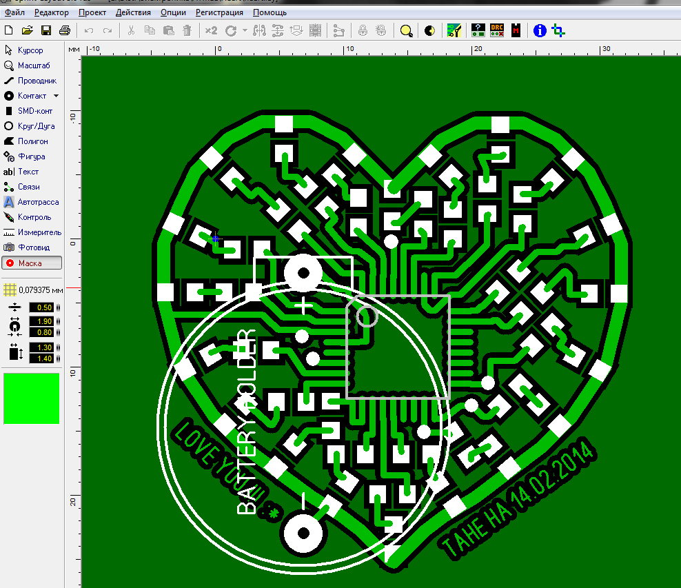
For a start, a box was chosen and bought, then, guided by the size, began to develop a board. For drawing used Sprint-Layout. The number of diodes was selected by the number of available, that is, 20 pcs. As a "heart": Atmega8.
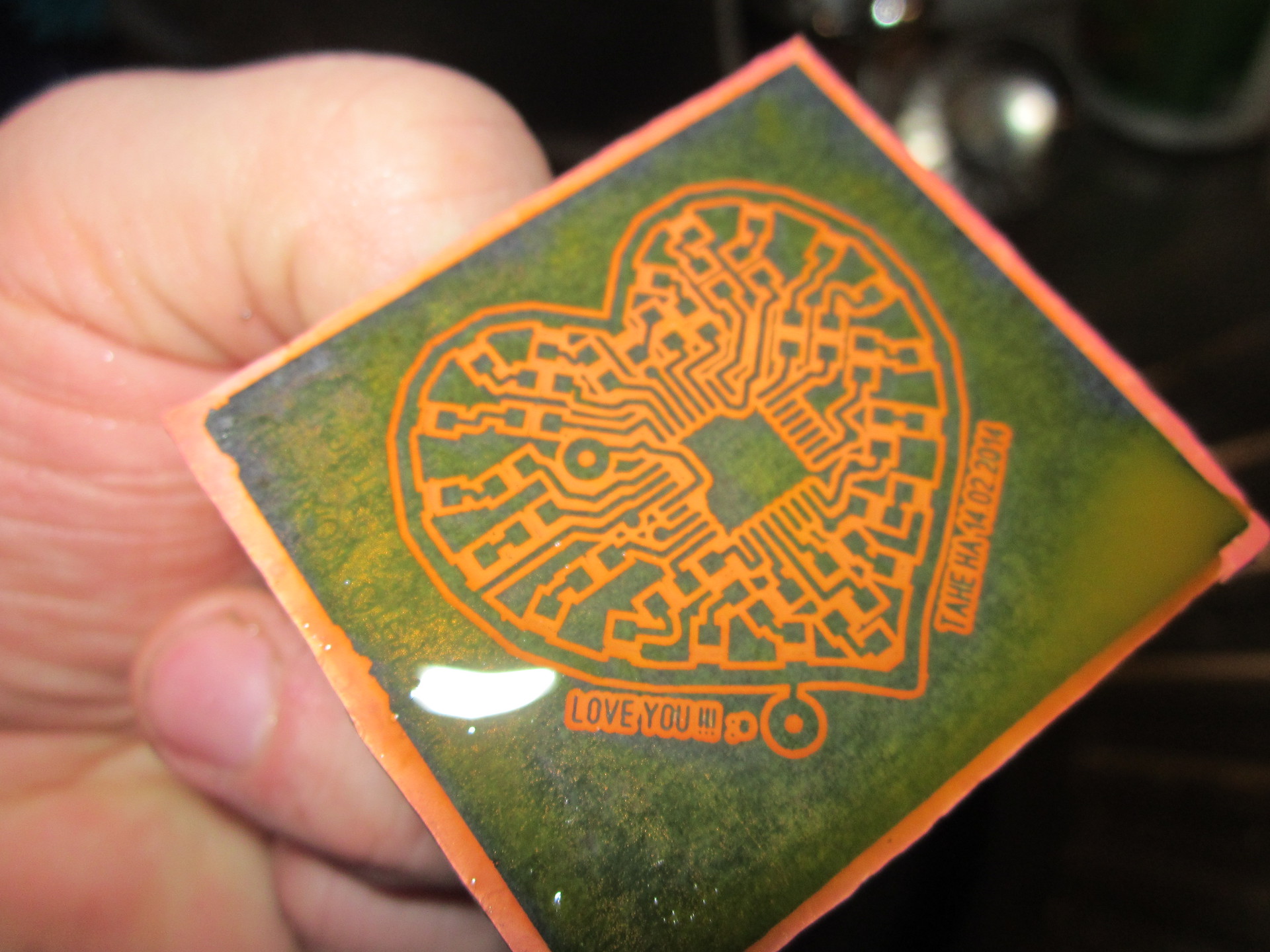
To convert the image to textolite used the good old LUT. That is, the printing was made by a laser printer on a smooth paper of an advertisement of a supermarket, and translated with an iron. When printing, the main thing is not to forget to mirror the image, and iron it carefully with an iron until all the tracks are visible through the paper. Washed paper in hot water without machining. I just waited until she crawled away, I had to wait about 20 minutes, it turned out to be a good paper.
')

Travil in a solution of ferric chloride, putting in the sink and turning on hot water. If you are preparing a fresh solution, when the powder is dissolved in water, heat is generated and it is not necessary to heat it. All subsequent uses of the solution must be warmed up, otherwise the etching process will be delayed and there will be a “peretrav” - sort of wormholes on the tracks.
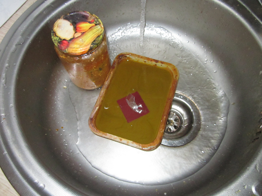
For the convenience of viewing the result, I glued a piece of stationery tape to the board.
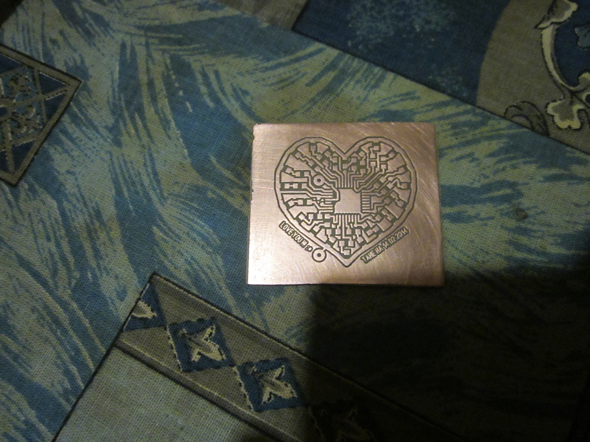
After the weed, he used a hard part of the dish sponge and soap to wipe the toner off the board. The result is satisfied, nothing extra is set off, the board looks like it was intended.
After decoupling all the elements, I realized that I had completely forgotten to withdraw the programming connector separately. I had to build another cable and solder straight to the board.

As a programming environment used CodeVisionAVR. Working with LEDs is probably a sort of “Hello World!” In microcontroller programming. To light the LED, we say the microcontroller to apply voltage to the desired leg.

A cr2032 battery was used for power. A piece of thin Plexiglas is fixed above the board, when the power cover is opened, it is fed by closing the reed switch located on the back wall of the box. For the long life of the device, the resistors are set to 1k, with periodic viewing, it has not yet been village (it was given on 02/14/2014).
I received a question about connecting the board through a reed switch. To do this, I had to do the following:
1. Trim the path going from the 4 legs of the MK to the five-way “+” connector on the battery (made even before the dressing, removing the toner)
2. Power from the "+" to wire through the reed switch to the 6th leg of the MK through the drilled hole. (that is, under the board)
Datashit on MK
Sources, binary and schema
For a start, a box was chosen and bought, then, guided by the size, began to develop a board. For drawing used Sprint-Layout. The number of diodes was selected by the number of available, that is, 20 pcs. As a "heart": Atmega8.
To convert the image to textolite used the good old LUT. That is, the printing was made by a laser printer on a smooth paper of an advertisement of a supermarket, and translated with an iron. When printing, the main thing is not to forget to mirror the image, and iron it carefully with an iron until all the tracks are visible through the paper. Washed paper in hot water without machining. I just waited until she crawled away, I had to wait about 20 minutes, it turned out to be a good paper.
')
Travil in a solution of ferric chloride, putting in the sink and turning on hot water. If you are preparing a fresh solution, when the powder is dissolved in water, heat is generated and it is not necessary to heat it. All subsequent uses of the solution must be warmed up, otherwise the etching process will be delayed and there will be a “peretrav” - sort of wormholes on the tracks.
For the convenience of viewing the result, I glued a piece of stationery tape to the board.
After the weed, he used a hard part of the dish sponge and soap to wipe the toner off the board. The result is satisfied, nothing extra is set off, the board looks like it was intended.
After decoupling all the elements, I realized that I had completely forgotten to withdraw the programming connector separately. I had to build another cable and solder straight to the board.
As a programming environment used CodeVisionAVR. Working with LEDs is probably a sort of “Hello World!” In microcontroller programming. To light the LED, we say the microcontroller to apply voltage to the desired leg.
A cr2032 battery was used for power. A piece of thin Plexiglas is fixed above the board, when the power cover is opened, it is fed by closing the reed switch located on the back wall of the box. For the long life of the device, the resistors are set to 1k, with periodic viewing, it has not yet been village (it was given on 02/14/2014).
I received a question about connecting the board through a reed switch. To do this, I had to do the following:
1. Trim the path going from the 4 legs of the MK to the five-way “+” connector on the battery (made even before the dressing, removing the toner)
2. Power from the "+" to wire through the reed switch to the 6th leg of the MK through the drilled hole. (that is, under the board)
Datashit on MK
Sources, binary and schema
Source: https://habr.com/ru/post/243141/
All Articles