Unreliable ethernet
In continuation of the previous article " Ethernet & FC ", I would like to give specific recommendations for optimizing the Ethernet network for working with NetApp FAS storage systems. Although, I believe, many things described here may be useful for other solutions.
For those who strongly doubt the "reliability" of Ethernet. Not that I want to completely convince everyone to switch from FC 8G to 10 GBE , but I want to remove a certain areola of mistrust and misunderstanding of technology. Any technician should always be rational and cool-headed. At the same time, the statements that “Ethernet is losing frames” can hardly be called an “unbiased approach” and “non-subjective thinking”. I propose to consider where did this stable opinion about the unreliability of Ethernet come from, in order to either debunk all doubts or confirm them with concrete justification.
So it all started with the birth of the standard, when Ethernet was 10 Mbit / s which used a coaxial cable shared medium. At the same time, the transmission of information was “half duplex”, i.e. at one time, time could be carried out by a single node or the transmission or reception of information. The more network nodes in one such domain, the more collisions were exacerbated by the “half duplex” situation; there were really lost frames. Then Ethernet took a step further and started using a twisted pair cable, providing the groundwork for the future, but stupid hubs just as well united all network nodes into one collision domain and the situation didn’t change. Smart devices appeared, with the proud name “switches”, they not only duplicated frames from one of their ports to another, they climbed inside the frame and memorized the addresses and ports where the frames came from and transmitted them only to the receiver's port. And everything would be fine, but collisions still remained in some form even in 100 Mbit / s networks, despite the fact that the collision domain was split up and reduced only to a node with a switch port, which in one-duplex mode “ran across” when they tried to send a frame to each other at the same time. What happened next - “duplexity” (10BASE-T, IEEE 802.3i) appeared, i.e. each node could simultaneously receive and transmit frames on different links: two pairs of RX and TX for the terminal and two for the switch. In 1 GBE half duplex mode no longer exists at all. What does it mean? Collisions disappeared forever ... They are no longer there. There remain two childhood diseases of the Ethernet, which are closely connected with each other, because the switches could “forget” the frames when the buffer overflowed, and this happened as a rule because of the “Ethernet loopbacks”. These problems solved accordingly: 1) DCB add-on for the Ethernet protocol, also known as Lossless Ethernet, is a set of protocols that, as in the case of FC, do not lose frames. 2) Just added more memory to the data center level switches. 3) A network of 10 GBE and Cisco in particular, stepped forward and offered TRILL in their line of Nexus switches for the data center . TRILL and FabricPath, which simply defines the purpose of the hop count field in the Ethernet frame, by analogy with the time to live field in the IP packet to prevent hooking, as well as some of the other functions “borrowed” from IP, thus saving the Ethernet from the latest childhood diseases.
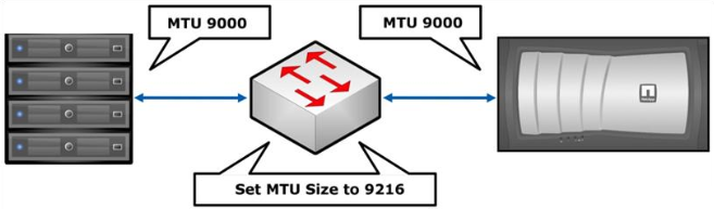
If NFS , iSCSI , CIFS protocols are used , it is recommended to include jumbo frame , on switches and hosts whenever possible. NetApp storage currently supports MTU 9000, which is currently the maximum value for Ethernet 10GB. In this case, the jumbo frame must be included along the entire path of the Ethernet frame: from source to destination. Unfortunately, not all switches and not all host network adapters support the currently “maximum” MTU , so apply some HP blade chassis with servers and integrated 10GB switches support a maximum of 8000 MTU , for such cases on the storage side it is necessary to select the most appropriate MTU value. Since there is some confusion about what an MTU is , there are difficulties in understanding which MTU value needs to be configured. So, for example, for normal operation of NetApp storage systems with the MTU 9000 value set on the Ethernet interface, it will be “normal” to work with switches for which the MTU value is set to one of the values: 9000 (Catalyst 2970/2960/3750/3560 Series), 9198 (Catalyst 3850 ), 9216 (Cisco Nexus 3000/5000/7000/9000, Catalyst 6000/6500 / Cisco 7600 OSR Series), on others this value should generally be 9252. As a rule, setting the MTU on the switch to the maximum allowable value (above or equal to 9000 ), everything will work. For clarification, I recommend reading the relevant article Maximum Transmission Unit (MTU). Myths and reefs .
Perform a setup from the command line on each Fabric Interconnect:
')
Flowcontrol settings must match for both: storage ports and switch ports connected to them. In other words, if the flowcontrol on the storage ports is set to none , then on the switch the flowcontrol should be set to off and vice versa. Another example: if the storage system sends flowcontrol send , then the switch must be configured to receive them ( flowcontrol receive on ). Not matching the settings of the flowcontrol leads to the rupture of established protocol sessions, for example, CIFS or iSCSI , the connection will be present, but due to constant session breaks it will work very slowly during an increase in the load on the link, and during small loads the problem will not manifest at all.

Do not confuse the “Normal” FlowControl with the PFC (IEEE 802.1Qbb) for DCB (Lossless) Eternet.
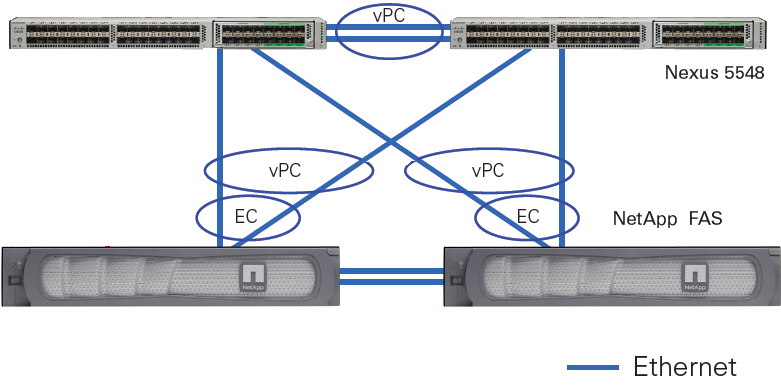
In the case of using NetApp with “classic Ethernet” (i.e., Ethernet which is “not at the Datacenter level”), it is highly recommended to enable RSTP , and configure the Ethernet ports to which the end nodes ( storage and hosts) are connected, with portfast mode enabled , TR-3749 . Datacenter Ethernet networks do not need a Spanning Tree at all; an example of such equipment is the Cisco Nexus series switches with vPC technology.
Considering the “universality” of 10 GBE , when FCoE , NFS , CIFS , iSCSI can walk along the same physics along with such technologies as vPC and LACP , as well as the simplicity of servicing Ethernet networks, the protocol and switches favorably distinguish FC “Maneuvering” and saving investments in the event of a change in business needs.
Internal tests of NetApp storage systems (for other storage vendors this situation may differ) FC 8G and 10 GBE iSCSI , CIFS and NFS show almost the same performance and latency typical for OLTP and server and desktop virtualization, i.e. for loads with small blocks and random read writing.
I recommend to get acquainted with the pack describing similarities, differences and perspectives of Ethernet & FC .
In the case when the customer's infrastructure implies two switches, then we can talk about the same complexity of configuring both SAN and Ethernet networks. But for many SAN customers, the network is not reduced to two SAN switches, where “everyone sees everyone”, as a rule, the configuration does not end at this point; in this respect, Ethernet maintenance is much simpler. Typically, a customer's SAN network is a multitude of switches with redundant links and links to remote sites, which is by no means trivial to maintain. And if something goes wrong, Wireshark traffic is not “listen”.
Modern converged switches, such as the Cisco Nexus 5500, are capable of switching both Ethernet and FC traffic, allowing for greater flexibility in the future thanks to the two-in-one solution.
Also do not forget about the possibility of port aggregation using EtherChannel LACP . It should also be understood that aggregation does not magically connect Ethernet ports, but only distributes (balances) traffic between them, in other words, two aggregated 10 GBE ports do not always “reach out” to 20 GBE . It is worth noting here that, depending on whether the storage system is in a separate IP subnet from the hosts, you need to choose the right balancing method. In the case when the storage system is located in a separate subnet from the hosts, it is impossible to choose MAC balancing (Destiny), since it will always be the same - the MAC address of the gateway. In the case when there are fewer hosts than the number of aggregated links on the storage system , the balancing does not work optimally due to the imperfection and limitations of the network load balancing algorithms. And vice versa: the more network nodes use an aggregated link and the “more correctly” the balancing algorithm is chosen, the more the maximum bandwidth of the aggregated link approaches the sum of the bandwidths of all links. For more details on the LACP balancing, see the article “ Aggregation of channels and traffic balancing over IP ”.
TR-3749 describes the nuances of VMWare ESXi configuration with NetApp storage systems and Cisco switches.
I am sure that over time I will have something to add to this article on network optimization, after a while, so look in here from time to time.
Comments on errors in the text and suggestions please send to the LAN .
Unreliable ethernet
For those who strongly doubt the "reliability" of Ethernet. Not that I want to completely convince everyone to switch from FC 8G to 10 GBE , but I want to remove a certain areola of mistrust and misunderstanding of technology. Any technician should always be rational and cool-headed. At the same time, the statements that “Ethernet is losing frames” can hardly be called an “unbiased approach” and “non-subjective thinking”. I propose to consider where did this stable opinion about the unreliability of Ethernet come from, in order to either debunk all doubts or confirm them with concrete justification.
So it all started with the birth of the standard, when Ethernet was 10 Mbit / s which used a coaxial cable shared medium. At the same time, the transmission of information was “half duplex”, i.e. at one time, time could be carried out by a single node or the transmission or reception of information. The more network nodes in one such domain, the more collisions were exacerbated by the “half duplex” situation; there were really lost frames. Then Ethernet took a step further and started using a twisted pair cable, providing the groundwork for the future, but stupid hubs just as well united all network nodes into one collision domain and the situation didn’t change. Smart devices appeared, with the proud name “switches”, they not only duplicated frames from one of their ports to another, they climbed inside the frame and memorized the addresses and ports where the frames came from and transmitted them only to the receiver's port. And everything would be fine, but collisions still remained in some form even in 100 Mbit / s networks, despite the fact that the collision domain was split up and reduced only to a node with a switch port, which in one-duplex mode “ran across” when they tried to send a frame to each other at the same time. What happened next - “duplexity” (10BASE-T, IEEE 802.3i) appeared, i.e. each node could simultaneously receive and transmit frames on different links: two pairs of RX and TX for the terminal and two for the switch. In 1 GBE half duplex mode no longer exists at all. What does it mean? Collisions disappeared forever ... They are no longer there. There remain two childhood diseases of the Ethernet, which are closely connected with each other, because the switches could “forget” the frames when the buffer overflowed, and this happened as a rule because of the “Ethernet loopbacks”. These problems solved accordingly: 1) DCB add-on for the Ethernet protocol, also known as Lossless Ethernet, is a set of protocols that, as in the case of FC, do not lose frames. 2) Just added more memory to the data center level switches. 3) A network of 10 GBE and Cisco in particular, stepped forward and offered TRILL in their line of Nexus switches for the data center . TRILL and FabricPath, which simply defines the purpose of the hop count field in the Ethernet frame, by analogy with the time to live field in the IP packet to prevent hooking, as well as some of the other functions “borrowed” from IP, thus saving the Ethernet from the latest childhood diseases.
Jumbo frame
If NFS , iSCSI , CIFS protocols are used , it is recommended to include jumbo frame , on switches and hosts whenever possible. NetApp storage currently supports MTU 9000, which is currently the maximum value for Ethernet 10GB. In this case, the jumbo frame must be included along the entire path of the Ethernet frame: from source to destination. Unfortunately, not all switches and not all host network adapters support the currently “maximum” MTU , so apply some HP blade chassis with servers and integrated 10GB switches support a maximum of 8000 MTU , for such cases on the storage side it is necessary to select the most appropriate MTU value. Since there is some confusion about what an MTU is , there are difficulties in understanding which MTU value needs to be configured. So, for example, for normal operation of NetApp storage systems with the MTU 9000 value set on the Ethernet interface, it will be “normal” to work with switches for which the MTU value is set to one of the values: 9000 (Catalyst 2970/2960/3750/3560 Series), 9198 (Catalyst 3850 ), 9216 (Cisco Nexus 3000/5000/7000/9000, Catalyst 6000/6500 / Cisco 7600 OSR Series), on others this value should generally be 9252. As a rule, setting the MTU on the switch to the maximum allowable value (above or equal to 9000 ), everything will work. For clarification, I recommend reading the relevant article Maximum Transmission Unit (MTU). Myths and reefs .
Jumbo Frames in Cisco UCS
Perform a setup from the command line on each Fabric Interconnect:
system jumbomtu 9216 policy-map type network-qos jumbo class type network-qos class-default mtu 9216 multi-cast-optimize exit system qos service-policy type network-qos jumbo exit copy run start ')
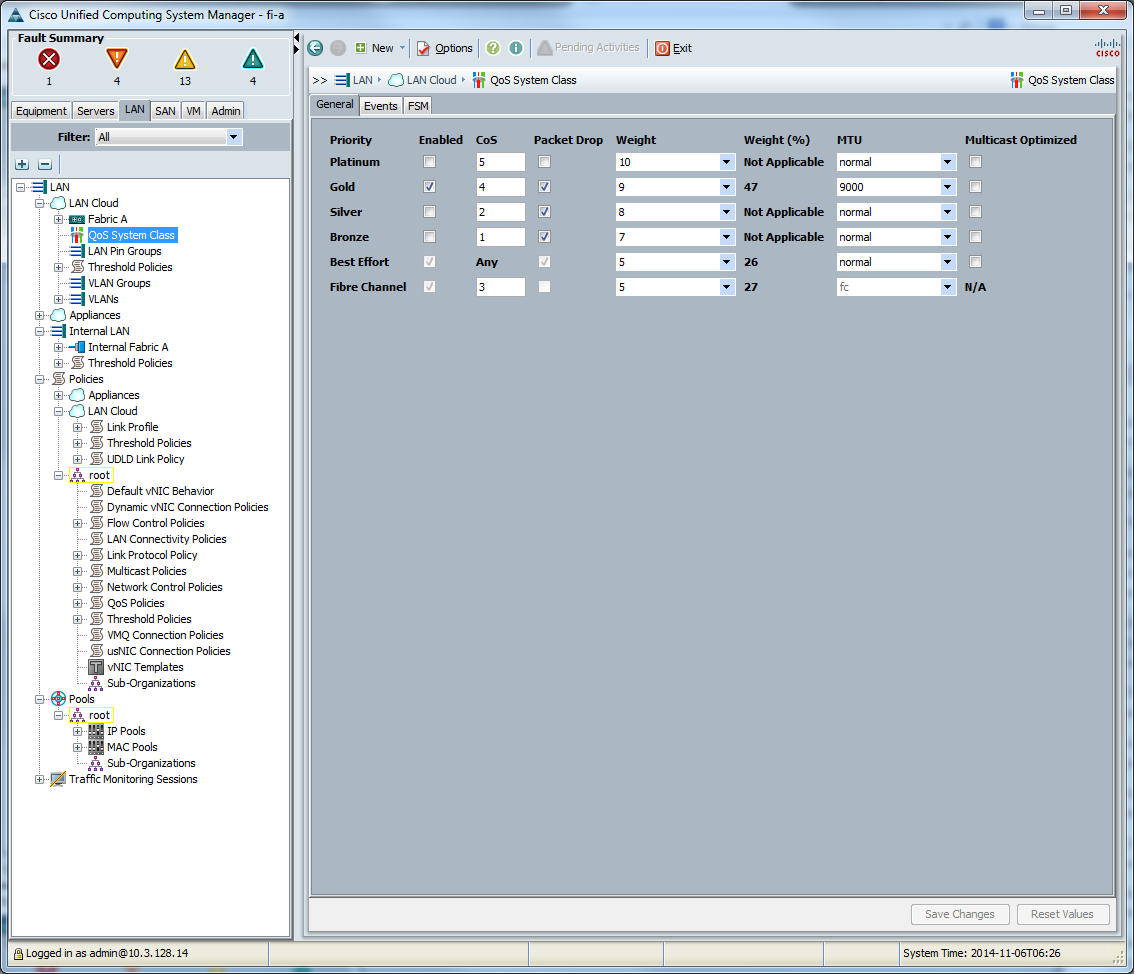
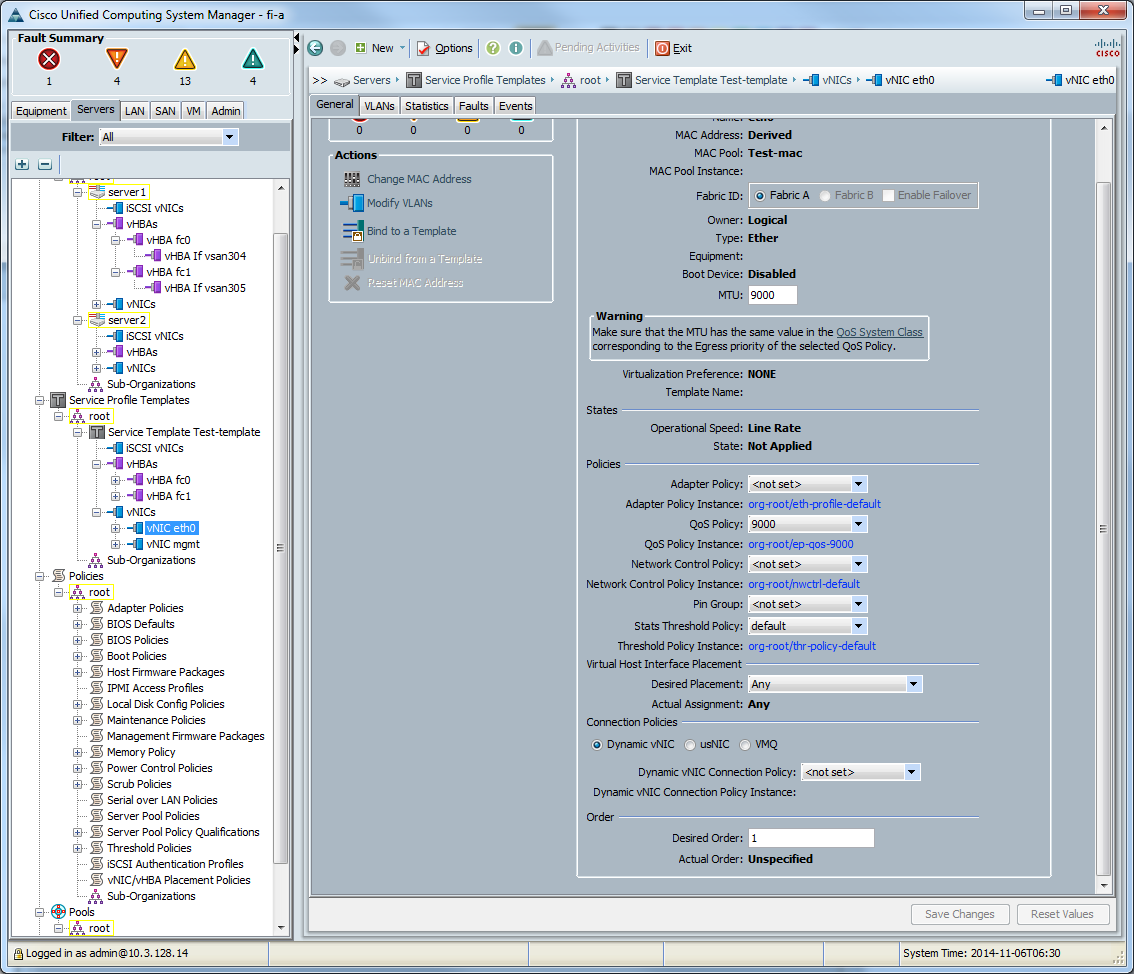
Or from UCS Manager GUI
In the UCS Manager settings when working with Ethernet, we configure the MTU in the “Lan> Lan Cloud> QoS System Class” tab, and we set the MTU to one selected class.
Then we create a “QoS policy”

Create a vNIC template
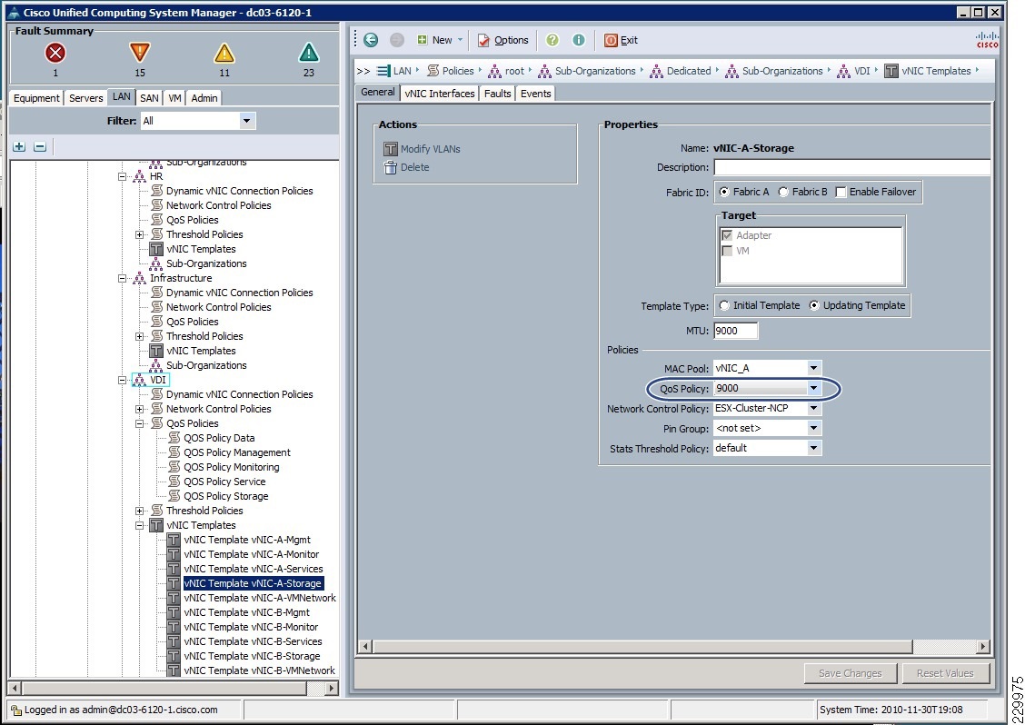
We bind to the network interface of the server.
Then we create a “QoS policy”
Create a vNIC template
We bind to the network interface of the server.
Flowcontrol
Flowcontrol settings must match for both: storage ports and switch ports connected to them. In other words, if the flowcontrol on the storage ports is set to none , then on the switch the flowcontrol should be set to off and vice versa. Another example: if the storage system sends flowcontrol send , then the switch must be configured to receive them ( flowcontrol receive on ). Not matching the settings of the flowcontrol leads to the rupture of established protocol sessions, for example, CIFS or iSCSI , the connection will be present, but due to constant session breaks it will work very slowly during an increase in the load on the link, and during small loads the problem will not manifest at all.
- As a general rule, if possible, do not include flowcontrol , TR-3428 .
- For 10GB networks, it is highly recommended not to enable flowcontrol .
- For 1GB networks, you can enable flowcontrol (as an exception to the rule): the storage sends the flow control, and the switch accepts — on the storage system, set the flowcontrol to send , and on the switch to Desired (or send / tx off & receive / rx on ).
- For 100 MB networks (as an exception to the rule), you can enable flowcontrol to receive and transmit on both: the storage and the switch send and receive flow control commands.
- For those who are interested in why such recommendations, you are here .
- Additionally see TR - 3802
- Examples of configuring storage and svitchiy can be found in the corresponding articles.
Do not confuse the “Normal” FlowControl with the PFC (IEEE 802.1Qbb) for DCB (Lossless) Eternet.
Spanning tree protocol
In the case of using NetApp with “classic Ethernet” (i.e., Ethernet which is “not at the Datacenter level”), it is highly recommended to enable RSTP , and configure the Ethernet ports to which the end nodes ( storage and hosts) are connected, with portfast mode enabled , TR-3749 . Datacenter Ethernet networks do not need a Spanning Tree at all; an example of such equipment is the Cisco Nexus series switches with vPC technology.
Converged network
Considering the “universality” of 10 GBE , when FCoE , NFS , CIFS , iSCSI can walk along the same physics along with such technologies as vPC and LACP , as well as the simplicity of servicing Ethernet networks, the protocol and switches favorably distinguish FC “Maneuvering” and saving investments in the event of a change in business needs.
FC8 vs 10GBE: iSCSI, CIFS, NFS
Internal tests of NetApp storage systems (for other storage vendors this situation may differ) FC 8G and 10 GBE iSCSI , CIFS and NFS show almost the same performance and latency typical for OLTP and server and desktop virtualization, i.e. for loads with small blocks and random read writing.
I recommend to get acquainted with the pack describing similarities, differences and perspectives of Ethernet & FC .
In the case when the customer's infrastructure implies two switches, then we can talk about the same complexity of configuring both SAN and Ethernet networks. But for many SAN customers, the network is not reduced to two SAN switches, where “everyone sees everyone”, as a rule, the configuration does not end at this point; in this respect, Ethernet maintenance is much simpler. Typically, a customer's SAN network is a multitude of switches with redundant links and links to remote sites, which is by no means trivial to maintain. And if something goes wrong, Wireshark traffic is not “listen”.
Modern converged switches, such as the Cisco Nexus 5500, are capable of switching both Ethernet and FC traffic, allowing for greater flexibility in the future thanks to the two-in-one solution.
LACP
Also do not forget about the possibility of port aggregation using EtherChannel LACP . It should also be understood that aggregation does not magically connect Ethernet ports, but only distributes (balances) traffic between them, in other words, two aggregated 10 GBE ports do not always “reach out” to 20 GBE . It is worth noting here that, depending on whether the storage system is in a separate IP subnet from the hosts, you need to choose the right balancing method. In the case when the storage system is located in a separate subnet from the hosts, it is impossible to choose MAC balancing (Destiny), since it will always be the same - the MAC address of the gateway. In the case when there are fewer hosts than the number of aggregated links on the storage system , the balancing does not work optimally due to the imperfection and limitations of the network load balancing algorithms. And vice versa: the more network nodes use an aggregated link and the “more correctly” the balancing algorithm is chosen, the more the maximum bandwidth of the aggregated link approaches the sum of the bandwidths of all links. For more details on the LACP balancing, see the article “ Aggregation of channels and traffic balancing over IP ”.
TR-3749 describes the nuances of VMWare ESXi configuration with NetApp storage systems and Cisco switches.
LACP Configuration Example
on NetApp 7-Mode
on NetApp Clustered ONTAP
Note that portfast (spanning-tree port type edge) must be configured BEFORE NetApp is connected!
On the Cisco Catalyst Switch:
On the Cisco Nexus 5000 switch:
vif create lacp <vif name> -b ip {Port list} on NetApp Clustered ONTAP
ifgrp create -node <node name> -ifgrp <vif name> -distr-func {mac | ip | sequential | port} -mode multimode_lacp ifgrp add-port -node <node name> -ifgrp <vif name> -port {Port 1} ifgrp add-port -node <node name> -ifgrp <vif name> -port {Port 2} Note that portfast (spanning-tree port type edge) must be configured BEFORE NetApp is connected!
On the Cisco Catalyst Switch:
cat(config)#interface gi0/23 cat(config)#description NetApp e0a Trunk cat(config)#switchport mode trunk cat(config)#switchport trunk allowed vlan 10,20,30 cat(config)#switchport trunk native vlan 123 cat(config)#flowcontrol receive on cat(config)#no cdp enable cat(config)#spanning-tree guard loop cat(config)#!portfast must be configured before netapp connection cat(config)#spanning-tree portfast cat(config)# cat(config)#int port-channel1 cat(config-if)#description LACP multimode VIF for netapp1 cat(config-if)#int gi0/23 cat(config-if)#channel-protocol lacp cat(config-if)#channel-group 1 mode active On the Cisco Nexus 5000 switch:
n5k(config)#interface EthernetX/X/X n5k(config-if)#switchport mode trunk n5k(config-if)#switchport trunk allowed vlan XXX n5k(config-if)#spanning-tree port type edge n5k(config-if)#channel-group XX mode active n5k(config)# n5k(config)#interface port-channelXX n5k(config-if)#switchport mode trunk n5k(config-if)#switchport trunk allowed vlan XX n5k(config-if)#!portfast must be configured before netapp connection n5k(config-if)#spanning-tree port type edge I am sure that over time I will have something to add to this article on network optimization, after a while, so look in here from time to time.
Comments on errors in the text and suggestions please send to the LAN .
Source: https://habr.com/ru/post/243119/
All Articles