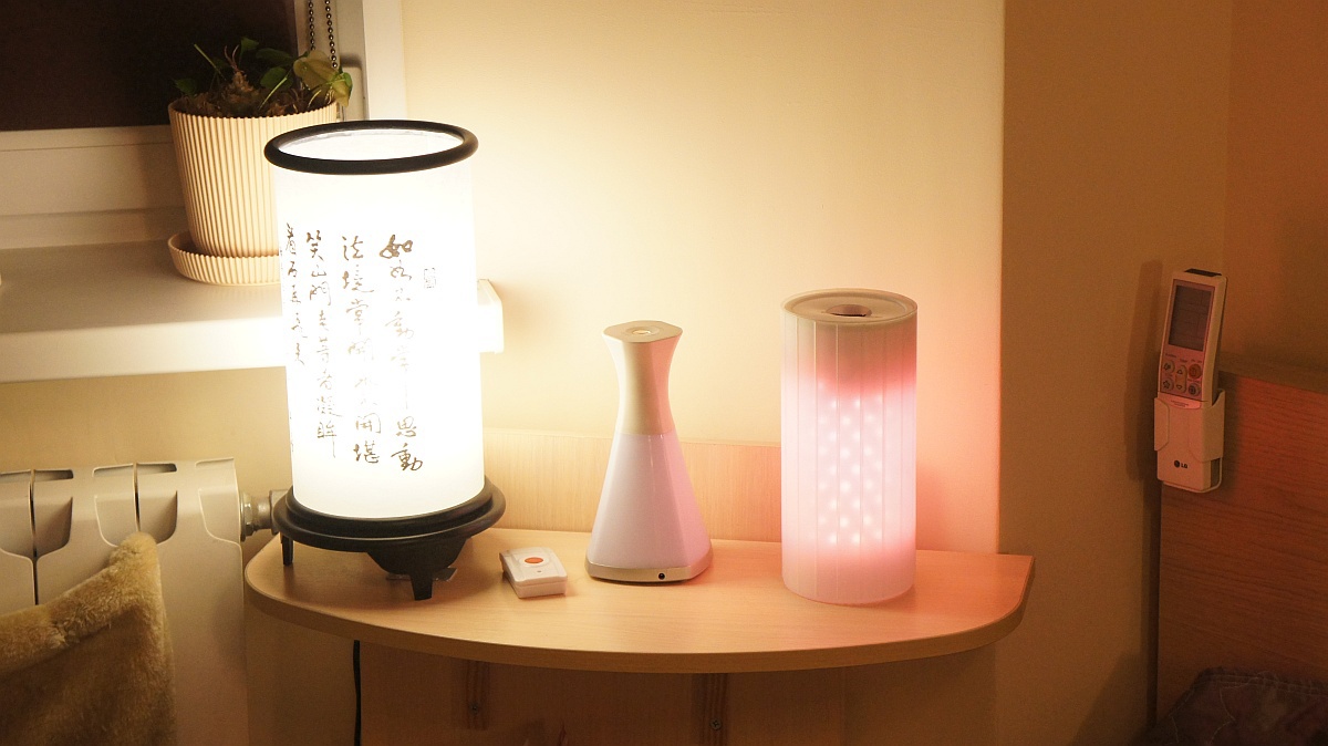
Decorative decorative lamp SDB-Z "Evlampiya"
Honestly, I do not remember how it all began. Suppose I was bored again and wanted some light even at the end of the tunnel, at least at the beginning. Little by little, the desire took shape in the night light, which is switched on with a wave of the hand. And later it was transformed into a decorative lamp with adjustable brightness, various hues of luminescence and all sorts of additional functions. Namely, temperature display overboard and control of lighting in the room.
And it all came out of the cheapest IKEA interior lamp, a couple of meters of LED tape, an Arduino, and a small handful of modules and components.
')
Meet Evlampiya
I would like some kind of official language like the “Evlampiya“ SDB-3 lamp ”is intended for use for decorative purposes inside residential premises”, but then it will be necessary to write about strict adherence to the instruction, which is absent. Therefore, I will be easier, especially since this is the basic principle of managing Evlampii.
.
So that she can:
1) To work as a nightlight . The light turns on and off with a horizontal wave of the hand above the lamp.
2) Work lamp background light . Brightness is regulated by the vertical movement of the hand above the lamp.
3) Show the temperature outside . More precisely - to visualize the range of temperatures. Each range - its shade. Receives data from the weather sensor on the radio.
4) Work as a decorative lamp with a manual tint change . The hue is changed by the vertical movement of the hand above the lamp.
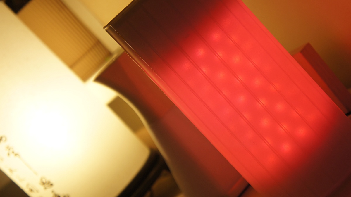
5) Work as a decorative lamp with a cyclical change in shade .
6) Control the light in the room * . Holding your hand at a certain height in normal lamp mode switches the background and overhead lights. And if you cover the lamp with your palm, then after three seconds all the upper light in the apartment and the background light in the room are turned off altogether.
* Controls Livolo switches and radio outlets with SC / PT2260 / 2262 chips and the like with fixed code.
As you might have guessed, the lamp is controlled by horizontal and vertical movements. At the same time, a horizontal swing or controls the nightlight, or switches in a circle modes (lamp, thermometer, manual rainbow, automatic rainbow).
This is explained by the fact that I wanted to somehow get away from all kinds of consoles, switches and other Wi-Fi. So that, you know, light and shades depended on, so to speak, manual dexterity. The hand, of course, is conditionally mentioned - any obstacle will do. But since people usually have hands, not obstacles, in the future - a hand.
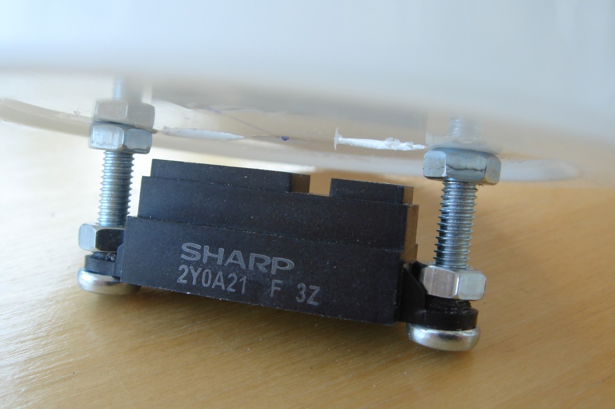
Given this specificity, I also chose the sensor - the Sharp infrared range finder, about which some individuals write that the target device is an automatic urinal, while others are wondering what kind of urinal this is, if some sensors in the family have a maximum working distance of about 40 cm. On the other hand, I know for sure that these sensors are used in vacuum cleaning robots to prevent collisions with obstacles.
Not the point.
The working distance of the selected sensor is 80 cm (although in fact it seems to be much more), and the output voltage is the higher, the closer the object. But as the obstacle approaches, there is a threshold after which the voltage will go down, despite the fact that the obstacle is getting closer. It is unpleasant, but not fatal, especially since in my case it is about 4 centimeters, which can be compensated for by “digging” the sensor into the design.
After selecting the sensor, I suddenly realized that I just didn’t have enough light. I wanted a rainbow, and many other buns - since all the same in the lamp will be a controller, the resources of which are almost not used. So in the list of components appeared LED RGB-tape instead of simple, 433 MHz receiver and transmitter, as well as a transistor assembly to control the tape. The latter seemed to me more attractive than just a few field effect transistors, do not ask why.
To not remain unclear points. The receiver is needed to obtain data on temperature and external commands - after all, it would be foolish to miss the opportunity to turn the lamp on and off with the background lighting console. The transmitter is necessary for controlling the external light: the background one based on the usual radio-controlled outlets and the top one via the radio-controlled Livolo switches.
Accessories
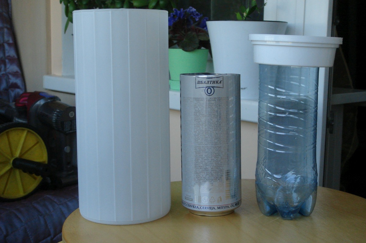
In short, I had an IKEA lamp, an Arduino Pro Mini debug, a prototype board, a Sharp distance sensor, a 433 MHz amplitude modulated transmitter and receiver, an RGB LED tape, a can of beer, a bottle of drinking water, a box of tooth powder, a 9V power adapter, a handful of fasteners and some wires. Not that this was enough to revive the Mir space station, but it was enough for Evlampia.
So (links for example only):
- KVARNE lamp;
- Infrared distance sensors Sharp GP2Y0A21YK , and then immediately datashit ;
- The 433 MHz receiver is superheterodyne because I was disappointed in the regenerative receivers. Either because they are, or because I cannot make an antenna normally;
- The 433 MHz transmitter is subjective - quite decent and, moreover, already with an antenna;
- Arduino Pro Mini ;
- Transistor Assembly ULN2003A ;
- RGB LED strip - to taste, I bought offline;
- The network adapter is also to the taste, I had some old 9V lying around (although it would probably be better to use 12V - because the tape is 12V);
- Aluminum can with a capacity of 0.5 liters from under any drink;
- Plastic bottle with a diameter under the inner diameter of the aluminum can;
- Bank of tooth powder with a diameter for the internal diameter of the lamp. It looks like this (I bought in a store near the house);
- Development board, installation wires - to taste;
- Optional: 10 μF capacitors, 0.1 μF, 10 kΩ resistor.
Scheme
Capacitors and pull-up resistor are optional, and are not shown in the diagram. I used them within the company to combat false positives, but in the end it turned out that phantom potentials had nothing to do with it.
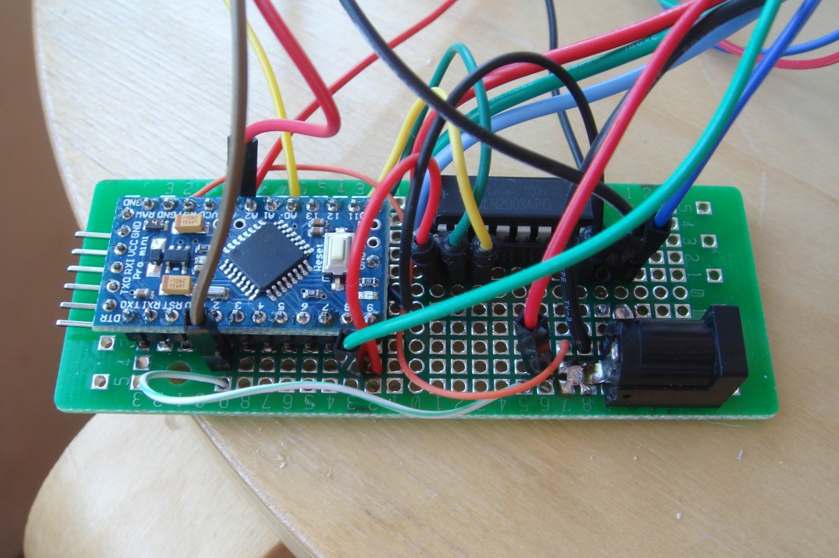
. I hope that more or less correctly painted.

. And so it looks like what happened according to the scheme. Sorry to be ugly. I am sure you will be better!
Be sure to pay attention to the power of the IR sensor and receiver. They need no more than 5V, so they eat from the Arduino stabilizer, and not directly from the power supply.
Miracle of miracles
The assembly of all this into a single whole turned out to be an absolutely incredible occupation. At least, starting with the fact that in addition to the IKEA lamp, you also needed a plastic bottle with a capacity of 0.5 liters, an aluminum can of the same container from under any beverage, and a plastic can of tooth powder. This is because the following concept arose in my head: RGB-tape is glued to an aluminum can. It turns out a certain analogue of the famous Chinese "corn", which is placed inside the ceiling of the lamp.
. source lamp, carefully divided
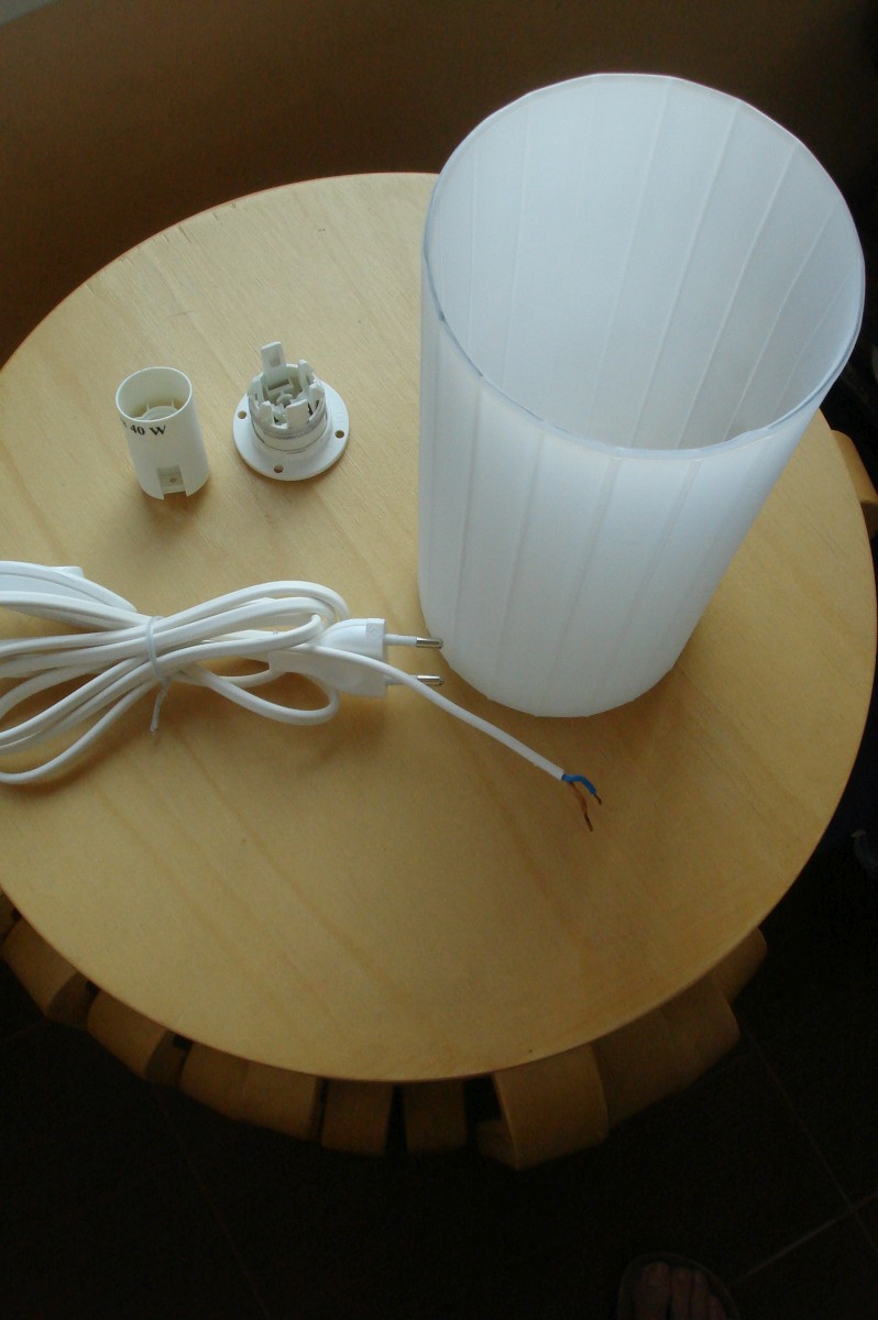
The bank here is needed to serve as a kind of heat sink and means to observe the geometry of the light emitter thus designed. According to the plan of the creator (ie me), the management board fits into the bank. But since the bank is metal, we protect ourselves against short-circuit conditions primitively: we lay inside a pre-cut plastic bottle that serves as an insulator.
Hence the law of Evlampii: the outer diameter of the bottle should not exceed the inner diameter of the can.
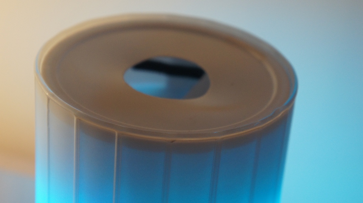
As for the can of tooth powder, it was required, first, to more or less aesthetically cover the top of the lamp from dust and curious glances. And at the same time - it is convenient to fix the sensor and place the receiver with the transmitter. Indeed, inside the metal can they have little chance of productive activity.
Other wonders in order:
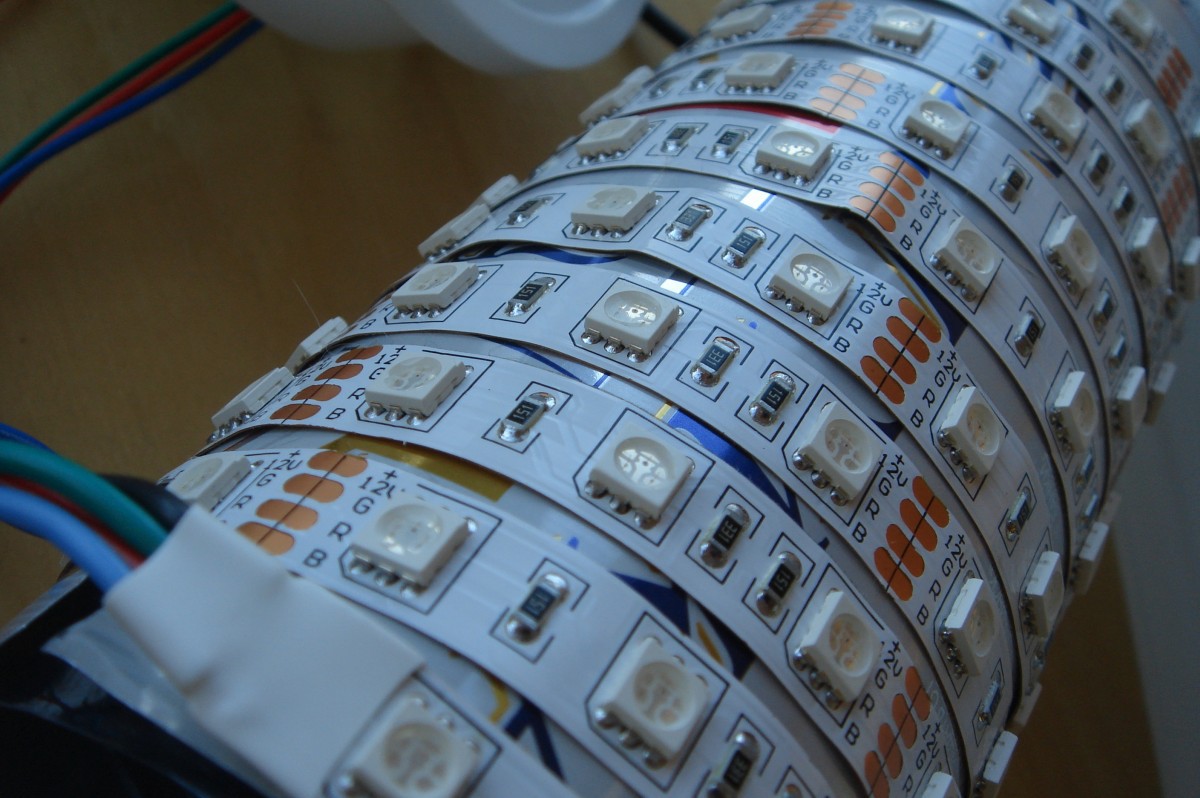
- a couple of meters of LED strip bought at random was just enough to wrap a can
- a jar with a carefully cut off tip perfectly fitted into the lamp
- bottle insulator perfectly fit in the bank
- a can of powder tooth in diameter almost fit into the inner diameter of the ceiling. “Practically” in this case means that there are minor violations of the geometry of the lid, which are partly due to the fact that the can body is still compressed, and partly because there was a hole in the can lid for the IR sensor.
. something like this deformation
"Kukuruzina" is attached to the cover in the lower point of it by regular fastening of the cartridge. Of course, “extra” elements had to be broken off from this attachment, but the fact remains.
In my version, the build process is:
1) Cut the top of the aluminum can and cut a hole in its bottom corresponding to the diameter of the hole in the nut that secures the lamp holder. We glue the nut to the bottom of the jar - in the future, all of it will be wound on the fastening of the cartridge.
. like this

2) From the fastening of the cartridge, we remove the cartridge itself and parts that interfere with the insertion of a wire with a plug to power the controller through the hole.
.

3) Here I would have to carefully cut off the bottom of the bottle and cut off its nose so that on one side this spout, being placed close to the bottom of the can, would prevent the controller from contacting metal walls, and on the other, that the bottle would not protrude beyond the can height. But since I made a mistake twice, I finally put the bottom of the bottle on the bottom of the jar (with a hole, of course, and the top (with an overly cut nose down) - the rest of the bottle.
.
4) We glue the LED strip around the can so as to create a sufficient density of LEDs and at the same time fit the length (2 meters). Glue from the bottom of the banks, feeding wires up to then lower them in the bank to the controller.
.
5) In a clean can of tooth powder, we make two large holes. In the bottom and in the lid, both under the sensor. The holes must be at least the diameter of the sensor. In the bottom, the hole can be almost any shape, but optimally rectangular, because next to it you need to make a couple of smaller holes - for the sensor mounting studs. It was convenient for me to make a round one in the lid, since it was actually marked up with factory stamping, and I neatly cut it out with an ordinary stationery-painting knife.
. At first I drilled two round holes for the sensor, but when it turned out that it had to be moved away from the edge of the can, I had to arrange a real “failure”, otherwise I would get a reflection from the bottom of the can
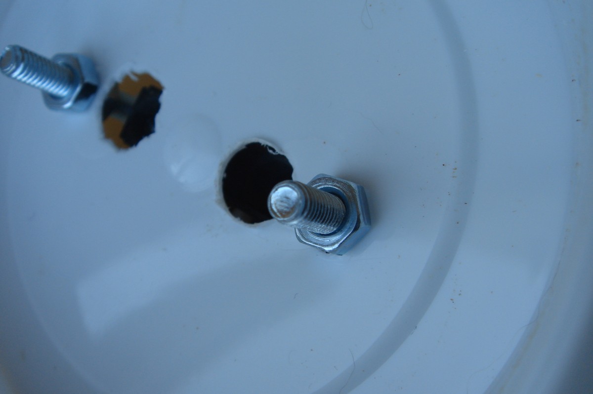
Carefully ream the sensor holes under the M4 (if there is an M3 fastener - take it and do not drill anything) and fit it on the screws, fixing with nuts.
.
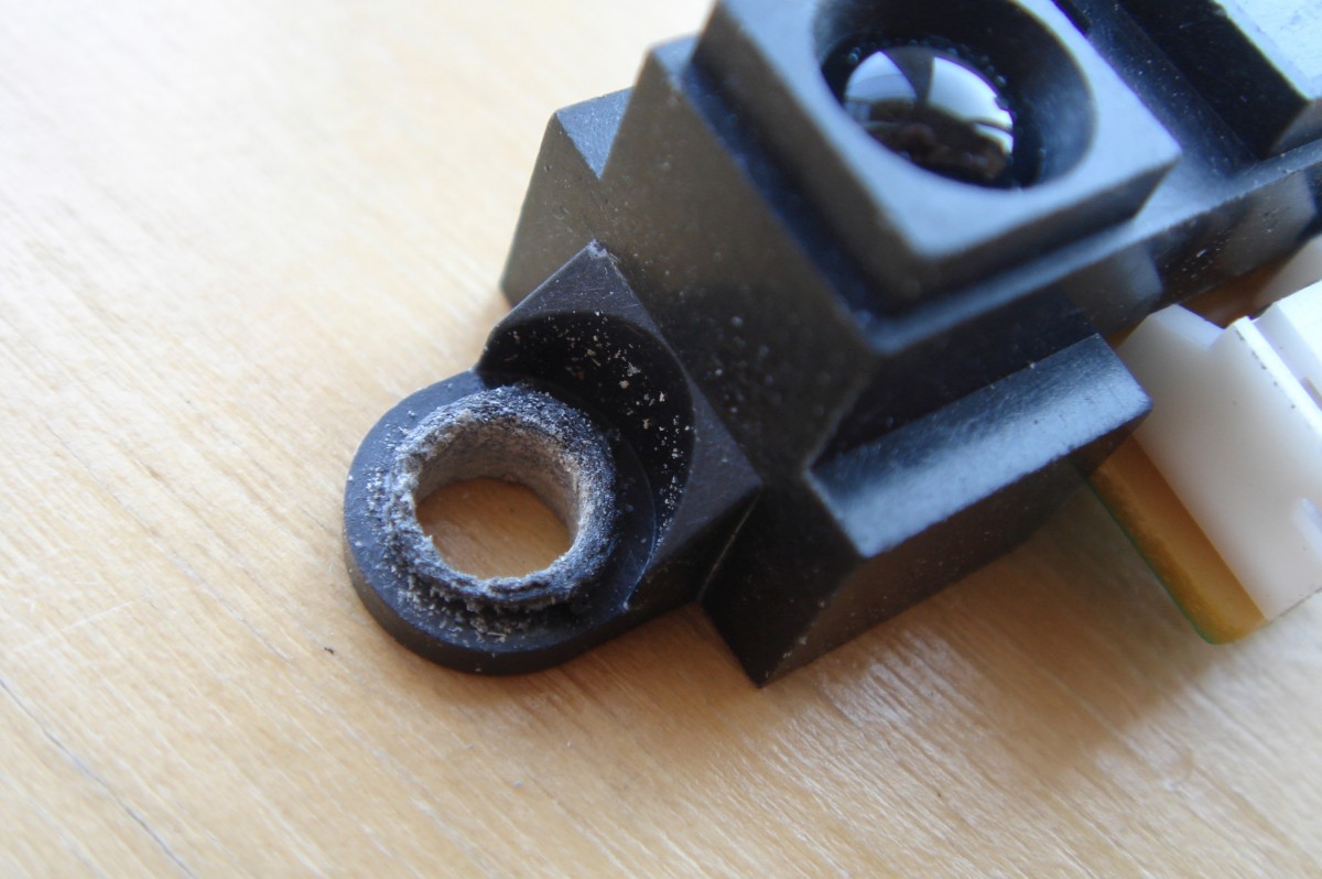
Screw the screws over the nut and pass them into the holes in the bottom of the jar, and on top - even on the nut. This design allows you to mechanically adjust the position of the sensor for fine adjustment of the base level. Looking ahead - the base level is the level at which Evlampiya believes that she was covered with a hand, and you need to turn off everything.
.
The bank will also require holes for the 433 MHz receiver and transmitter wires, which also need to be more or less carefully placed there.
6) We connect to the controller LED strip, IR sensor, 433 MHz receiver and transmitter. We pass through the power supply cable into the ceiling and also connect it to the controller.
. here you can see partially a rectangular hole in the bottom of the “dental” can

7) We put the controller in the corn, close the entire structure with a can of tooth powder.
eight) ?!!!
9) PROFIT !!!
Algorithm
Here I tried to portray the algorithm of the Evlampia function core, excluding radio control. Also, this algorithm is part of an infinitely executable loop.

Code
In addition to the code, you will need two libraries:
You will also need to first empirically find out, and then in the variables section, set the working range of the sensor, depending on how you place it.
These are the variables top and bottom , marked with comments “top of the zone of adjustment” and “bottom of the zone of adjustment”.
There are also debug lines left in the code - you can enable them if necessary.
ps until Evlampiya gets the temperature, in the display mode it flashes in three colors in succession and switches to the next mode.
All that is acquired by overwork
// beta 3 - // beta 4 - , // beta 4 - // beta 4 - : /* -35 - -25 0 -25 - -15 15 -15 - 0 - 50 0 - 15 - 85 15 - 20 100 20 - 25 - 170 25 - 30 - 235 30+ 254 // : if (colorV < 100) { targetR = colorV*0.05; } else { targetR = 5+(colorV-100)*1.29; } // if (colorV < 75) { // 0 - 180 targetG = 2.4*colorV; } if (colorV > 75 && colorV < 100) { // 180 - 254 targetG = 180 + (colorV-75)*2.96; } if (colorV > 100 && colorV < 150) { // 254 targetG = 254; } if (colorV > 150 && colorV < 200) { // 254 - 154 targetG = 254 - (colorV-150)*2; } if (colorV > 200) { // 154 - 0 targetG = 154 - (colorV-200)*2.85; } // if (colorV < 100) { targetB = 254 - colorV*2.54; } else { targetB = colorV*0.05; } */ #include <RCSwitch.h> // SC2260/2262 http://code.google.com/p/rc-switch/ #include <livolo.h> // Livolo #define txPin 8 // Livolo livolo(8); // Livolo RCSwitch mySwitch = RCSwitch(); // RC-Switch int weatherData = 0; unsigned long dimmerDelay, timerStart, timerStop, timerSwitchStart, timerSwitchStop, timerRange; // int prevRange, nowRange, tempRange, switchRange, vectorRange, initRange, rangeFinder, tempC; byte nightLightLevel, rainbow, delta, redB, greenB, blueB, targetL, targetR, targetG, targetB, lastValueRGB; byte lightMode = 0; // (0 - , 1 - , 2 - , 3 - , 4 - ) byte lastMode = 1; // byte valueRGB = 0; // ( nowRange) boolean rainbowUp, followMeLight; // boolean timing = false; // ( ) boolean switchLock = false; // boolean tempLock = false; // boolean backLight = false; // boolean mainLight = false; // boolean nightLight = false; // boolean tempRcvd = false; // #define nightLightLimit 65 // #define rangePin A0 // #define redPin 9 // #define greenPin 10 // #define bluePin 11 // #define bottom 630 // #define top 135 // #define delta 20 // #define shortDelay 350 // #define longDelay 3000 #define timeOutRange 100 // "" , #define rainbowStep 75 // #define dimmerStep 35 // void setup() { // Serial.begin(9600); pinMode(rangePin, INPUT); pinMode(redPin, OUTPUT); pinMode(greenPin, OUTPUT); pinMode(bluePin, OUTPUT); mySwitch.enableTransmit(txPin); // mySwitch.enableReceive(0); // ( 0 -> 2) rgbLight(0, 0, 0); // lastMode = 1; // timerRange = millis(); // nowRange = getRange(); // } void loop() { // if ((millis() - timerRange) > timeOutRange) { // timeOutRange prevRange = nowRange; // nowRange = getRange(); // timerRange = millis(); // // Serial.print("Range: "); // Serial.println(nowRange); } // -- ( ), - ( ) if ((nowRange < bottom + delta) && (nowRange > top)) { // if (nowRange > bottom - delta) { // "" (2*delta) valueRGB = 0; } else { valueRGB = 254 - map(nowRange, top, bottom, 0, 254); // 0 - 254 "" } // Serial.print("valueRGB: "); // Serial.println(valueRGB); // if (lightMode == 1) { // if (valueRGB > 70 && valueRGB < 110) { // followMeLight = true; // , lastValueRGB = valueRGB; // rgbLight(0, 255, 0); // "" // Serial.println("Set Green to 255"); } else { if (valueRGB > 175 && valueRGB < 215) { // followMeLight = true; lastValueRGB = valueRGB; // rgbLight(0, 0, 255); // "" // Serial.println("Set Blue to 255"); } else { if (valueRGB > 235) { // followMeLight = true; lastValueRGB = valueRGB; // rgbLight(valueRGB, 0, 0); // // Serial.println("Set RED"); } else { lastValueRGB = valueRGB; followMeLight = false; } } } } // if (timing == false) { // timerStart = millis(); // timerSwitchStart = millis(); // timing = true; // } if (timing == true) { // ( ) // tempRange = nowRange - prevRange; // if (abs(tempRange) > delta) { // timerStart = millis(); // } if ((millis() - timerStart) > longDelay) { // // if (lightMode == 0 && switchLock == false) { // - lightMode = lastMode; switchLock = true; // } // ( ) if (lightMode == 1 && switchLock == false) { // // if ((nowRange > (bottom/2)) && (nowRange < (bottom - 2*delta))) { // , +4*delta // // Serial.print("Backlight mode (nowRange): "); // // Serial.println(nowRange); // // Serial.print("backLight:"); // // Serial.println(backLight); if (backLight == false) { // // mySwitch.send(863029, 24); // backLight = true; switchLock = true; // // Serial.println("Backlight ON"); // // Serial.print("backLight:"); // // Serial.println(backLight); } else { // // mySwitch.send(863028, 24); // backLight = false; switchLock = true; // // Serial.println("Backlight OFF"); // // Serial.print("backLight:"); // // Serial.println(backLight); } } // if ((nowRange < (bottom/2)) && (nowRange > top)) { // , /* // Serial.print("Main light mode (nowRange): "); // Serial.println(nowRange); // Serial.print("mainLight:"); // Serial.println(mainLight); */ if (mainLight == false) { // // livolo.sendButton(8500, 0); // livolo.sendButton(8500, 96); // mainLight = true; switchLock = true; /* // Serial.println("Main light ON"); // Serial.print("mainLight:"); // Serial.println(mainLight); */ } else { // // livolo.sendButton(8500, 0); // livolo.sendButton(8500, 96); // mainLight = false; switchLock = true; /* // Serial.println("Main light OFF"); // Serial.print("mainLight:"); // Serial.println(mainLight); */ } } } // if (nowRange > (bottom - delta)) { // (2*delta) // Serial.print("Full off mode (nowRange): "); // Serial.println(nowRange); if (lightMode > 0 && switchLock == false) { // blinkLight(150); rgbLight(0, 0, 0); // livolo.sendButton(8500, 106); // mySwitch.send(863028, 24); // mainLight = false; backLight = false; lastMode = lightMode; // lightMode = 0; // switchLock = true; // } } } // > longDelay } // timing = true // if (lightMode == 1) { if (followMeLight == false) { // , // Serial.println("Brightness control"); rgbLight(valueRGB, valueRGB, valueRGB); } } // if (lightMode == 3) { if (valueRGB > 0) { // colorRGB(valueRGB); } else { rgbLight(0, 0, 0); // } } } // nowRange > bottom // , if ((nowRange < (top + delta))) { if (timing == true) { // if (lightMode == 1) { rgbLight(lastValueRGB, lastValueRGB, lastValueRGB); // followMeLight = false; } unsigned long millistart = millis() - timerSwitchStart; if (millistart < shortDelay) { // // if (lightMode == 0 && switchLock == false) { // if (nightLight == false) { // nightLightLevel = 0; nightLight = true; // } else { nightLightLevel = nightLightLimit; nightLight = false; // } dimmerDelay = millis(); // } // if (lightMode > 0) { // lightMode = lightMode + 1; // blinkLight(150); if (lightMode == 4) { // dimmerDelay = millis(); // if (nowRange < 255) { // rainbow = nowRange; rainbowUp = true; } else { rainbow = 254; rainbowUp = false; // } } if (lightMode == 3) { // - colorRGB(valueRGB); } if (lightMode == 2) { if (tempRcvd == true) { colorRGB(tempC); // } else { noTemp(); } } if (lightMode > 4) { // lightMode = 1; } } } // < longDelay } // timing = true timing = false; switchLock = false; // } // nowRange < bottom + delta if (nightLight == true && nightLightLevel < nightLightLimit) { // , if ((millis() - dimmerDelay) > dimmerStep) { // dimmerStep nightLightLevel++; rgbLight(nightLightLevel, nightLightLevel, nightLightLevel); dimmerDelay = millis(); // } } if (nightLight == false && nightLightLevel > 0) { // , if ((millis() - dimmerDelay) > dimmerStep) { nightLightLevel--; rgbLight(nightLightLevel, nightLightLevel, nightLightLevel); dimmerDelay = millis(); // } } // if (lightMode == 2) { if (valueRGB > 0) { // if (tempRcvd == true) { if (tempLock == false) { // colorRGB(tempC); // tempLock = true; // } else { noTemp(); } } } else { rgbLight(0, 0, 0); tempLock = false; } } // if (lightMode == 4) { if (valueRGB > 0) { // if ((millis() - dimmerDelay) > rainbowStep) { // Serial.print("Rainbow value: "); // Serial.println(rainbow); if (rainbowUp == true) { if (rainbow < 254) { rainbow++; } else { rainbowUp = false; } } if (rainbowUp == false) { if (rainbow > 1) { rainbow--; } else { rainbowUp = true; } } colorRGB(rainbow); dimmerDelay = millis(); } } else { rgbLight(0, 0, 0); } } if (mySwitch.available()) { // int value = mySwitch.getReceivedValue(); if (value != 0) { // if (lightMode == 0) { if (mySwitch.getReceivedValue() == 863029) { lightMode = 1; rgbLight(254, 254, 254); switchLock = true; } } // if (mySwitch.getReceivedValue() == 863028) { rgbLight(0, 0, 0); // mainLight = false; // backLight = false; if (lightMode == 0) { lastMode = 1; } else { lastMode = lightMode; // } lightMode = 0; // switchLock = true; // } if (mySwitch.getReceivedValue()/100000 == 161) { weatherData = mySwitch.getReceivedValue() - 16100000; if (weatherData < 10000) { // if (weatherData > 1000) { // if (weatherData > 1250) { // -25 tempC = 0; } if (weatherData < 1250 && weatherData > 1150) { // -25 -- -15C tempC = 15; } if (weatherData < 1150) { // -15C -- 0C tempC = 50; } } else { // if (weatherData > 300) { // +30 tempC = 254; } if (weatherData > 250 && weatherData < 300) { // +25C -- +30 tempC = 235; } if (weatherData > 200 && weatherData < 250) { // +25C -- +30 tempC = 170; } if (weatherData > 150 && weatherData < 200) { // +15C -- +25 tempC = 100; } if (weatherData < 150) { // +15 tempC = 85; } } tempRcvd = true; tempLock = false; // // tempC = tempC*0.363; // 0 255 // Serial.print("TempC: "); // Serial.println(tempC); } } mySwitch.resetAvailable(); } } } // loop void rgbLight(byte redL, byte greenL, byte blueL) { analogWrite(redPin, redL); analogWrite(greenPin, greenL); analogWrite(bluePin, blueL); } void colorRGB(int colorV) { // : if (colorV < 100) { targetR = colorV*0.05; } else { targetR = 5+(colorV-100)*1.29; } // if (colorV < 75) { // 0 - 180 targetG = 2.4*colorV; } if (colorV > 75 && colorV < 100) { // 180 - 254 targetG = 180 + (colorV-75)*2.96; } if (colorV > 100 && colorV < 150) { // 254 targetG = 254; } if (colorV > 150 && colorV < 200) { // 254 - 154 targetG = 254 - (colorV-150)*2; } if (colorV > 200) { // 154 - 0 targetG = 154 - (colorV-200)*2.85; } // if (colorV < 100) { targetB = 254 - colorV*2.54; } else { targetB = colorV*0.05; } rgbLight(targetR, targetG, targetB); } void blinkLight(byte spark) { for (byte i = 0; i < 3; i++) { rgbLight(0, 0, 0); delay(75); rgbLight(spark, spark, spark); delay(75); } } unsigned int getRange(){ byte i; unsigned int rangeFinder = 0; for (i = 0; i < 100; i++) { rangeFinder = rangeFinder + analogRead(rangePin); } rangeFinder = rangeFinder/100; return rangeFinder; } // void noTemp() { rgbLight(254, 0, 0); // delay(500); rgbLight(0, 254, 0); delay(500); rgbLight(0, 0, 254); delay(500); blinkLight(150); // lightMode = 3; // } Special features
Which is typical, the lamp turned out, as usual, despite the fact that I am already a scientist. In other words, I did not collect anything entirely until I checked the work in all modes. Works.
Then I put everything in the case and again checked the work in all modes. Works.
Left a day for surprises. There were no surprises. works.
Put on the bedside shelf. The lamp has gone mad. Namely: if it was in the nightlight mode, it began to turn on and off continuously; if she was in luminaire mode, she constantly switched modes. To my misfortune, I compared these problems with the location of the power wire and the location of the relative battery lamp. I thought that these were potential sources of interference that could affect the operation of the sensor and the microcontroller.
Then the lamp then worked fine, it did not work. To return it to work, I constantly twisted it and the wire; I bought an APC network filter socket, put 10 μF and 0.1 μF capacitors in parallel with the sensor power supply and pulled up the controller input, to which the sensor is connected to ground through a 10 kΩ resistor. Nothing helped, but it was embarrassing that the lamp went crazy at arbitrary points in time. In the end, I took the will into a fist and disassembled the structure to see what was going on in her soul.
While acquainting myself with the rich inner world of Evlampia, he accidentally turned the sensor and found that although the distance to the nearest object was more than 80 centimeters, the sensor readings changed. And here I understood a lot. Moreover, if you recall my mention of this sensor in robots, it is surprising that I did not immediately think about it.
So, the sensor responds differently to various obstacles. For example, a light wall or a dark door, judging by the behavior of the robot vacuum cleaner, are very different things. But the cat - generally akin to a black hole. In other words, when I first launched Eulampia in test mode, I set the limits of the working range of the sensor for a specific place - where, in fact, I checked. But on the bedside shelf everything turned out differently.
In general, after I changed the upper limit of the range, Evlampia became completely obedient.
The second feature is the realization of the rainbow (northern lights). Since I am not a mathematician at all, I just figured out exactly how to mix colors, and built a graph from the corresponding segments. The attentive observer will note that the lamp spends most of the time in the green range. And for this there is a reason: the same “color generator” is used for displaying the temperature and for the rainbow.
And since in my opinion in my home region it is more important to have an idea of the range from, say + 5C to + 25C, then the consequences are appropriate.
Source: https://habr.com/ru/post/243037/
All Articles