Power Raspberry Pi using Arduino
Many probably know that it’s not difficult to supply power to the Arduino from the Raspberry Pi, you just need a USB cable. The inverse problem looks more complicated, since most Arduino controllers do not have a USB output (Due is an exception). Nevertheless, it is possible to do this using GPIO pins, and I want to talk about a specific example for the Arduino Nano V3.0 and Raspberry Pi B rev.2. In addition to the power supply itself, I will also tell you how you can control this power using a button and a MOSFET transistor.
Most Arduino-compatible controllers use 5V pins. The only exception is the Arduino Due and 3.3V output from the Arduino, but this is not the case now. It is also known that one of the ways to power the Raspberry Pi is to use 5V and GND pins on the 26-pin P1 connector:

It would seem that the solution is obvious - you need to connect the Raspberry Pi to any of the Arduino pins, and everything will work. My attempt to do this led to the fact that the Raspberry Pi lit the PWR LED, but the ACT LED did not light up. The reason is a very small current strength from Arduino pins (about 40-50 mA). But the Arduino has a separate pin 5V, which (according to the link ) can produce about 400-500 mA. Now you need to check whether there is enough such current to power the Raspberry.
For normal power, the Raspberry Pi with two USB devices connected needs about 700 mA. Each USB device can consume up to 140 mA ( source ). Raspberries can consume even more current if it is overclocked (mine is not). Thus, if you use a non-overclocked RPi without USB devices, then the current strength from the Arduino 5V pin should be quite enough.
In order to control the power supply, you need a few more ingredients: a power button and something that can control large currents. I used a MOSFET transistor for this purpose. We proceed directly to the used parts.
')
I used the following "iron" parts:
For the Arduino firmware, you need an IDE, I used version 1.5.8 BETA, but stable 1.0.6 is also suitable. You will also need my small PowerButton library (link at the end of the article in the utility section).
Connection diagram looks like this:

The schematic diagram is as follows:
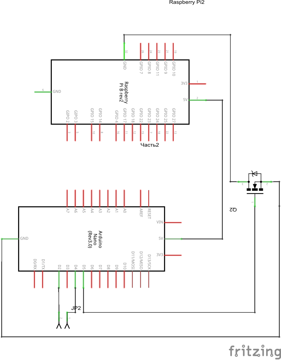
Explanation of schemes:
The connection with the D2 pin is not accidental: the library uses interrupts for the button, while the Arduino Nano only has the D2 / D3 pins for this purpose (you can check which pins on your Arduino support interrupts here ).
Most of the actions are taken by the library, so the code is very simple.
Short video with testing:
As you can see, visually everything works. But still it is necessary to check the voltage between the pins TP1 / TP2 (method here ). I got the value of ~ 4.6V, the recommended value is greater than 4.75V.
Despite the fact that everything works, there is still a suspicion that when connecting the periphery of the current from 5V, the Arduino pin will not be enough. MOSFET and the button work fine in a pair, such a bundle can be useful for further projects.
Utilities and libraries used for writing:
Since this is my first post, reviews and comments will be very helpful.
Theoretical opportunity
Most Arduino-compatible controllers use 5V pins. The only exception is the Arduino Due and 3.3V output from the Arduino, but this is not the case now. It is also known that one of the ways to power the Raspberry Pi is to use 5V and GND pins on the 26-pin P1 connector:
It would seem that the solution is obvious - you need to connect the Raspberry Pi to any of the Arduino pins, and everything will work. My attempt to do this led to the fact that the Raspberry Pi lit the PWR LED, but the ACT LED did not light up. The reason is a very small current strength from Arduino pins (about 40-50 mA). But the Arduino has a separate pin 5V, which (according to the link ) can produce about 400-500 mA. Now you need to check whether there is enough such current to power the Raspberry.
For normal power, the Raspberry Pi with two USB devices connected needs about 700 mA. Each USB device can consume up to 140 mA ( source ). Raspberries can consume even more current if it is overclocked (mine is not). Thus, if you use a non-overclocked RPi without USB devices, then the current strength from the Arduino 5V pin should be quite enough.
In order to control the power supply, you need a few more ingredients: a power button and something that can control large currents. I used a MOSFET transistor for this purpose. We proceed directly to the used parts.
')
Required hardware and software
I used the following "iron" parts:
- Raspberry Pi B rev. 2;
- Arduino Nano V3.0;
- button to control the power (I used the button with latching and signal wire);
- MOSFET transistor (I turned out to be IRF530N);
- Breadboard and several wires.
For the Arduino firmware, you need an IDE, I used version 1.5.8 BETA, but stable 1.0.6 is also suitable. You will also need my small PowerButton library (link at the end of the article in the utility section).
Scheme
Connection diagram looks like this:
The schematic diagram is as follows:
Explanation of schemes:
- D2 is connected to the SIG pin on the button.
- D4 is connected to the VCC pin on the button.
- D5 is connected to the MOSFET gate.
The connection with the D2 pin is not accidental: the library uses interrupts for the button, while the Arduino Nano only has the D2 / D3 pins for this purpose (you can check which pins on your Arduino support interrupts here ).
Source code for the Arduino
#include <PowerButton.h>
#define POWER_PIN_SIG 2
#define POWER_PIN_VCC 4
#define POWER_FET_GATE 5
#define POWER_PIN_INT 0
PowerButtonSwitch pbs ;
void onPowerOn ( ) {
Serial. println ( "Power On" ) ;
digitalWrite ( POWER_FET_GATE, 1 ) ; // Open the gate (gate)
}
void onPowerOff ( ) {
Serial. println ( "Power Off" ) ;
digitalWrite ( POWER_FET_GATE, 0 ) ; // Close the gate (gate)
}
void setup ( ) {
Serial. begin ( 9600 ) ;
// Output signal from Arduino to the gate MOSFET (gate)
pinMode ( POWER_FET_GATE, OUTPUT ) ;
digitalWrite ( POWER_FET_GATE, 0 ) ;
// Initial Power Button Setup
pbs setupPowerButton ( POWER_PIN_SIG, POWER_PIN_VCC, POWER_PIN_INT ) ;
// Read the current value
// If there is a signal from the button,
// turn on Raspberry Pi
int st = pbs. getSwitchStatus ( ) ;
if ( st == POWER_ON ) {
onPowerOn ( ) ;
}
// Add event handlers
pbs onPowerOn ( onPowerOn ) ;
pbs onPowerOff ( onPowerOff ) ;
}
void loop ( ) {
// Empty loop
delay ( 1000 ) ;
Serial. println ( "No actions" ) ;
}
Most of the actions are taken by the library, so the code is very simple.
Testing the solution
Short video with testing:
As you can see, visually everything works. But still it is necessary to check the voltage between the pins TP1 / TP2 (method here ). I got the value of ~ 4.6V, the recommended value is greater than 4.75V.
Conclusion
Despite the fact that everything works, there is still a suspicion that when connecting the periphery of the current from 5V, the Arduino pin will not be enough. MOSFET and the button work fine in a pair, such a bundle can be useful for further projects.
Utilities and libraries used for writing:
- Fritzing : used for drawing diagrams, available here .
- actually library for PowerButton : it is possible to take with GitHub here .
Since this is my first post, reviews and comments will be very helpful.
Source: https://habr.com/ru/post/242739/
All Articles