Increase the range of sensors weather stations Oregon Scientific
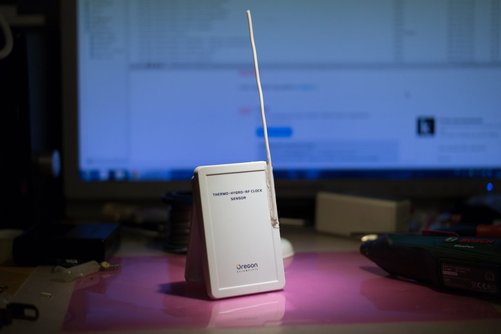
Some time ago I finally unified the meteorological stations in my apartment - I put Oregon Scientific BAR800 and BAR801 in all the right places, which I dearly love not only for the design that allows me to hang them on the wall, but also for the external sensor that receives accurate time signals. The trick is that these signals (DCF-77 from Frankfurt) are basically caught at home, but only at the window or outside the window - therefore, the usual weather stations, in which the antenna is built into the station itself, are standing in the back of the apartment, really nothing don't know. Of course, using the same type of stations means that you can do for all with one sensor and not hang the zoo by the windows.
Further, however, a problem was discovered that was also related to the depth of the apartment — the station most distant from the external weather sensor was losing it regularly, although it would seem that there was only a couple of walls between them. Especially this problem got out at sub-zero temperatures, despite the lithium battery in the sensor.
Choosing the right window for hanging the sensor or installing a second sensor is not our option, because a person should command the equipment, and not vice versa. Our option is to change the antenna in the sensor in order to increase its range.
')
Of course, the technique is suitable for any meteorological sensors, since the design of them all is about the same.
Unscrew:
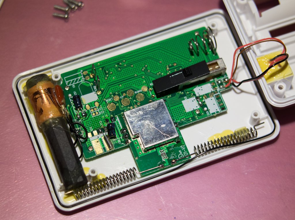
In this sensor - as many as three antennas at once (usually you will find one, maximum two). The ferrite rod, however, does not interest us - it is a receiver of time signals at 77 kHz, but two wire spirals are what we need.
They form the so-called half-wave dipole - antenna, consisting of two symmetrical parts with a total length of 1/2 wavelength. Dipoles are used when the antenna does not have a normal "ground" - one of the halves of the dipole just fulfills the role of this "earth", forgive the radio engineers for a somewhat simplified description. Each half has, respectively, a length of 1/4 wave.
The sensor operates at a frequency of 433.92 MHz, respectively, half of its wavelength is 34.5 cm. In order not to make an antenna of such dimensions, it is performed in the form of not a pin, but spirals - the latter has one interesting property: if the diameter of the turns the spiral is much smaller than the wavelength, it works like a conventional whip antenna, radiating in a plane perpendicular to its axis, but it turns out to be several times shorter. Spiral antennas became widespread long before the appearance of weather stations - first of all, in portable radios, for which the length of a 1/4-wave pin on the 27 MHz range is almost 3 meters. The three-meter-high pin makes the radio much less wearable than it could be.
Alas, all magic comes with a price: a spiral antenna has worse characteristics than a simple pin. Therefore, a spiral is always a compromise between size and efficiency.
So, in order to slightly increase the range of the sensor, we need to change the spiral antenna with a pin - the antenna dimensions worry the logistics department of the manufacturer, but we do not care much about consumers - there is a lot of space on the balcony, a 17-cm antenna will somehow fit.
To accomplish this, you will need a piece of single-core copper wire insulated with a length of 16.5 cm (one lived from any copper power cable with a section of 1.5-2.5 sq. Mm), a soldering iron, sealant, minimally straight arms.
NB: since in copper the wave propagation velocity is less than in vacuum, the actual length of the copper antenna must be less than 1/4 of the wavelength in vacuum; for copper, the correction factor is 0.95. Accordingly, 1/4 * (0.95 * 3 * 10 ^ 10 cm / s) / 433.92 MHz gives us approximately 16.5 cm.
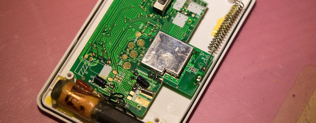
If you look at the transmitter board, you can see that one part of the dipole is connected to the ground, the other to the path going under the screen of the transmitting part. We will change one half of the dipole - the one to the transmitting part. We unsolder it:
We put the board in place and through the hole into which the antenna was soldered (clearing it of solder), with a needle, mark the point on the sensor body, through which the new antenna will go. We drill a hole near this point, we clean the last 5 mm of the antenna from isolation, bend it with the letter “G” and insert it into the hole in the body.
Since the hole in the board is much smaller in diameter than the wire taken as an antenna, we cut off 5 mm of some thin wire (the output of a 0.125 W resistor is suitable) and solder to the end of the antenna (drill a hole near the desired point and not right in it , it was necessary just that this soldering exactly got into the board):
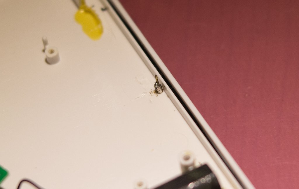
It is necessary to solder quickly so as not to melt the plastic case. In principle, it was possible to make an antenna from a thin wire, but this is inconvenient - it is easy to crumple and bend.
Put on top of the transmitter board, hitting the board hole in our antenna, solder it to the board, close the transmitter. The final touch is to fix the antenna on its body and seal the input; I used a glue gun, but, first of all, I have a gun with a very thin sting, and secondly, the sensor hangs under the roof, it does not water the rain. If you have another - use any sealant or thick glue. The upper end of the antenna is also advisable to close a drop of glue so that water does not fall on the copper conductor.
Actually, this is all. It is actually done faster than this text is written. Suitable for any weather stations, and indeed any home radio transmitters, up to the systems of "smart home", as the spiral antennas are used almost everywhere where you need cheap and angry. Pay only attention to the operating frequency: transmitters are also at 866 MHz, and completely new ones - at 2.4 GHz (in these, however, the antenna is most often already made a track on the board). The whip antenna should be 1/4 wave long.
PS The feeling of beauty also says that the best way to determine the ideal length of an antenna is to make it a little longer than 1/4 wave and then cut off by a millimeter, checking the efficiency. Reason answers that for a banal meteorological station this is too much.
Further, however, a problem was discovered that was also related to the depth of the apartment — the station most distant from the external weather sensor was losing it regularly, although it would seem that there was only a couple of walls between them. Especially this problem got out at sub-zero temperatures, despite the lithium battery in the sensor.
Choosing the right window for hanging the sensor or installing a second sensor is not our option, because a person should command the equipment, and not vice versa. Our option is to change the antenna in the sensor in order to increase its range.
')
Of course, the technique is suitable for any meteorological sensors, since the design of them all is about the same.
Unscrew:
In this sensor - as many as three antennas at once (usually you will find one, maximum two). The ferrite rod, however, does not interest us - it is a receiver of time signals at 77 kHz, but two wire spirals are what we need.
They form the so-called half-wave dipole - antenna, consisting of two symmetrical parts with a total length of 1/2 wavelength. Dipoles are used when the antenna does not have a normal "ground" - one of the halves of the dipole just fulfills the role of this "earth", forgive the radio engineers for a somewhat simplified description. Each half has, respectively, a length of 1/4 wave.
The sensor operates at a frequency of 433.92 MHz, respectively, half of its wavelength is 34.5 cm. In order not to make an antenna of such dimensions, it is performed in the form of not a pin, but spirals - the latter has one interesting property: if the diameter of the turns the spiral is much smaller than the wavelength, it works like a conventional whip antenna, radiating in a plane perpendicular to its axis, but it turns out to be several times shorter. Spiral antennas became widespread long before the appearance of weather stations - first of all, in portable radios, for which the length of a 1/4-wave pin on the 27 MHz range is almost 3 meters. The three-meter-high pin makes the radio much less wearable than it could be.
Alas, all magic comes with a price: a spiral antenna has worse characteristics than a simple pin. Therefore, a spiral is always a compromise between size and efficiency.
So, in order to slightly increase the range of the sensor, we need to change the spiral antenna with a pin - the antenna dimensions worry the logistics department of the manufacturer, but we do not care much about consumers - there is a lot of space on the balcony, a 17-cm antenna will somehow fit.
To accomplish this, you will need a piece of single-core copper wire insulated with a length of 16.5 cm (one lived from any copper power cable with a section of 1.5-2.5 sq. Mm), a soldering iron, sealant, minimally straight arms.
NB: since in copper the wave propagation velocity is less than in vacuum, the actual length of the copper antenna must be less than 1/4 of the wavelength in vacuum; for copper, the correction factor is 0.95. Accordingly, 1/4 * (0.95 * 3 * 10 ^ 10 cm / s) / 433.92 MHz gives us approximately 16.5 cm.
If you look at the transmitter board, you can see that one part of the dipole is connected to the ground, the other to the path going under the screen of the transmitting part. We will change one half of the dipole - the one to the transmitting part. We unsolder it:
We put the board in place and through the hole into which the antenna was soldered (clearing it of solder), with a needle, mark the point on the sensor body, through which the new antenna will go. We drill a hole near this point, we clean the last 5 mm of the antenna from isolation, bend it with the letter “G” and insert it into the hole in the body.
Since the hole in the board is much smaller in diameter than the wire taken as an antenna, we cut off 5 mm of some thin wire (the output of a 0.125 W resistor is suitable) and solder to the end of the antenna (drill a hole near the desired point and not right in it , it was necessary just that this soldering exactly got into the board):
It is necessary to solder quickly so as not to melt the plastic case. In principle, it was possible to make an antenna from a thin wire, but this is inconvenient - it is easy to crumple and bend.
Put on top of the transmitter board, hitting the board hole in our antenna, solder it to the board, close the transmitter. The final touch is to fix the antenna on its body and seal the input; I used a glue gun, but, first of all, I have a gun with a very thin sting, and secondly, the sensor hangs under the roof, it does not water the rain. If you have another - use any sealant or thick glue. The upper end of the antenna is also advisable to close a drop of glue so that water does not fall on the copper conductor.
Actually, this is all. It is actually done faster than this text is written. Suitable for any weather stations, and indeed any home radio transmitters, up to the systems of "smart home", as the spiral antennas are used almost everywhere where you need cheap and angry. Pay only attention to the operating frequency: transmitters are also at 866 MHz, and completely new ones - at 2.4 GHz (in these, however, the antenna is most often already made a track on the board). The whip antenna should be 1/4 wave long.
PS The feeling of beauty also says that the best way to determine the ideal length of an antenna is to make it a little longer than 1/4 wave and then cut off by a millimeter, checking the efficiency. Reason answers that for a banal meteorological station this is too much.
Source: https://habr.com/ru/post/242481/
All Articles