Thermoweder running Arduino and LabVIEW
Hi, Habr!
I work at the Institute of General Physics, RAS. The profile of our laboratory is laser remote sensing, specifically lidars. If you do not know what kind of animals, you can read, for example, on Wikipedia . Lidars are sometimes also called laser radars. The principal difference and advantage of lidar is that with its help one can not only measure the distance to the sensing object by the delay of the return signal, but also obtain (by the signal spectrum) information on the composition and properties of the object. For example, there are lidar methods for determining the temperature profile of water by depth in water bodies.
Non-contact measurements are only useful to the extent that they are accurate, therefore, to calibrate the results of remote measurements with contact measurements, it was decided to make a thermowax - a train of several thermal sensors on one line.
The contactless method using lidar makes it possible to measure the water temperature to a depth of several meters (it depends on transparency, it is clear that in dirty water the laser beam quickly dissipates and does not go far), therefore the thermowell is small, consists of five thermal sensors placed on the cable with an interval 1 m, plus another 4 m of cable, counting from the “upper” sensor.
')
I chose DS18B20 digital thermometers ( datasheet , 320 kb) in a sealed version as sensitive elements, such as:
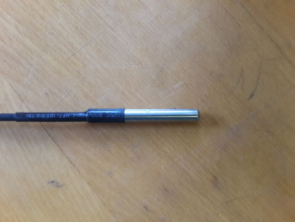
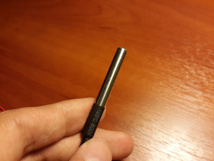
Why precisely such? Because they are sealed (smile), they are already delivered with a cable of 1 m length, they provide high accuracy and work using the 1-Wire protocol, which greatly simplifies communication with them.
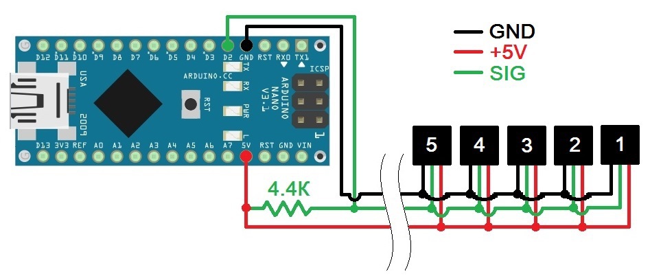
A thoughtful study of the datasheet gave the following information. Sensors can be connected in two ways: normal, via three wires (ground, “plus” power and signal bus) and in “stray” mode, when the sensor is powered from the data line. “Spurious” mode even more simplifies the connection (only two wires), but can sometimes distort the sensor readings. Any deterioration in accuracy is bad for us, and from the Arduino board that controls the sensors, 5 volts are easily accessible, so I decided to power the sensors in the usual way.
Thermal Mowers
Datashit recommends using a pull-up resistor of 4.7 kOhm, I only had two on the farm at 2.2, but this did not affect the performance of the device.
Arduino Nano with the ATMega328P controller is responsible for controlling the sensors and for communicating with the outside world, that is, with a PC.
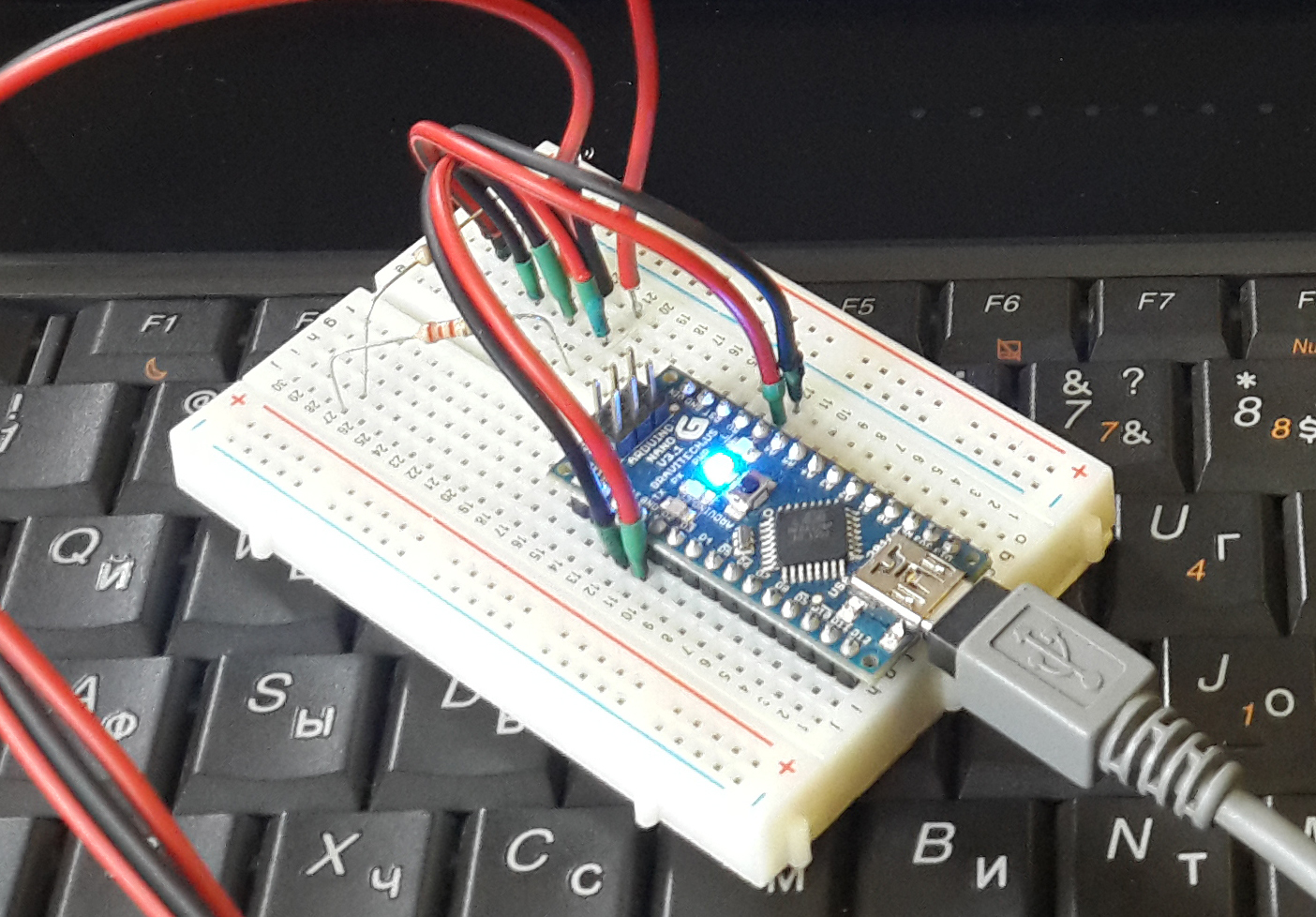
Here is the scheme assembled on the breadboard:
So - the final version after soldering and insulating:
And this is the entire assembly of the mower (the control electronics is not isolated):

I chose the Arduino as the “brains” of the device, firstly, because this platform is easy to learn, and secondly, because it can be controlled from a PC from under LabVIEW (hereafter LabVIEW = LV for short), which is important since the software of most of our laboratory’s projects is written in this environment, and the possibility of embedding a simple automated temperature control system in other schemes is expensive.
The main feature of this task is to work with the device from the LV environment; therefore, it was decided to start programming with studying the interaction of Arduino and LV. On Habré there is practically no information about this interaction, therefore, with your permission, I will describe everything in sufficient detail.
So, what we need (information from here ):
To start working with Arduino in LV, you need to flash your controller with the LIFA_Base.ino sketch taken from the C: / Program Files / National Instruments / LabVIEW [version] /vi.lib/LabVIEW Interface for Arduino / Firmware / LIFA_Base / folder. In this folder is a bunch of files - C-shnye libraries, sources and two sketches, LabVIEWInterface.ino and LIFA_Base.ino . The first contains descriptions of all the functions for working with Arduino, the second is very short and gathers everything together for uploading to the controller.
Voila, we now have access to most of the Arduino’s capabilities from the computer via LV. As you can guess, the first thing I did when I figured out everything described above was blinking with a LED.
Played, now for the cause.
The 1-Wire protocol and DS18B20 thermal sensors have been around for a long time and are widely distributed, so I decided to look for information on the sharing of DS18B20 and Arduino. And almost immediately I came across a suitable source, and not just anywhere, but on the official LabVIEW forum ( link ). Topikstarter had a similar task to me - to read the DS18B20 temperature sensor with Arduino from LabVIEW. He began searching and in a video clip on YouTube he saw the LV diagram with the OneWire Read VP present and asked the guru what kind of VP it was and where to get hold of it. The author of the video responded to his request and provided the source code and detailed instructions on how and what to do.
DS18B20 sensors are controlled as follows: the “master” (controller, microprocessor) sends a two-digit hexadecimal command through the data line, depending on which the sensor measures the temperature, receives bytes from the master to write to its memory, or sends the current contents of the memory to the data line . The author of the video modified the sketches that are uploaded to Arduino to work with LIFA:
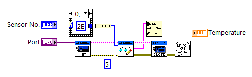
The proposed VP, in essence, merely sends the hexadecimal number 1E to the serial interface port indicated to it, waits for the answer and reads it:
It's pretty simple.
First I edited LIFA_BASE.ino and LabVIEWInterface.ino in accordance with the instructions and made the VP. Checked, everything works, great. Then I did something that I later regretted. In the above topic on the LV forum, a couple of posts below one of the participants proposed his version of the VP, which reads the temperature sensor readings, consisting essentially of only one sub-device - Send Receive.vi from the Arduino subframe:
Being tempted by simplicity and not having penetrated into the details, in my further experiments I used this simple version without any doubt. No, no, everything is fine and good, it works correctly, however, there is a certain subtlety associated with the differences between my scenario of the sensor-Arduino-LabVIEW chain and the scenario for which the VP was made from the forum. This subtlety gave me a certain amount of headache later, but more on that later.
One of the features of the DS18B20 sensors is that each individual copy has its own unique 8-byte address (ROM code), wired into it during the production process. This theoretically allows you to hang an unlimited number of sensors on a single 1-Wire line. To implement this feature, an addressing command to a specific sensor is provided.
To be addressed, you need to know the address. I recognized the ROM codes of my sensors using the example of the DS18x20_Temperature from the OneWire library, and recorded them in five variables declared at the beginning of the program:
In the proposed version, OneWire_Read does not receive any values. Add a parameter to it - the address of the sensor (byte array of 8 elements):
Before each sending of a command, we address the sensor:
and add a variant to each sensor in the selection structure:
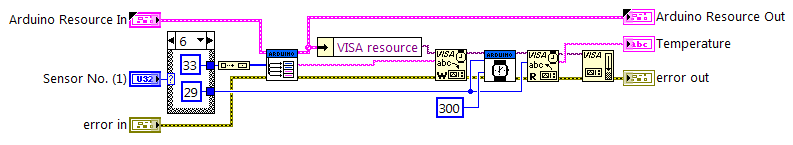
To test what happened, I made my small VI for a single poll of one sensor:
As you can see, I implemented the choice of the sensor for the survey through the case-structure in the block diagram.
For the convenience of future use, I made a small runway, as shown in the screenshot below, wasworn out and painted a nyashny icon for it and called DS18B20 Read.
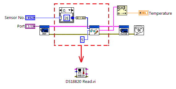
Apart from the Arduino resource clusters and errors, the runway receives the sensor number for polling and the output reads the temperature as a string.
Hooray! The tests were successful.
Well, we now know how to manually poll one sensor. The next step is a cyclical survey of one sensor in automatic mode. For this, I made the following block diagram:
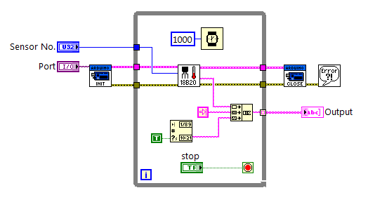
To begin with, the interval is fixed, the program polls the sensor once a second, and after the cycle is stopped, the user writes the collected data to the array. For convenience, I added a time stamp to each temperature reading using the Get Date / Time String function.
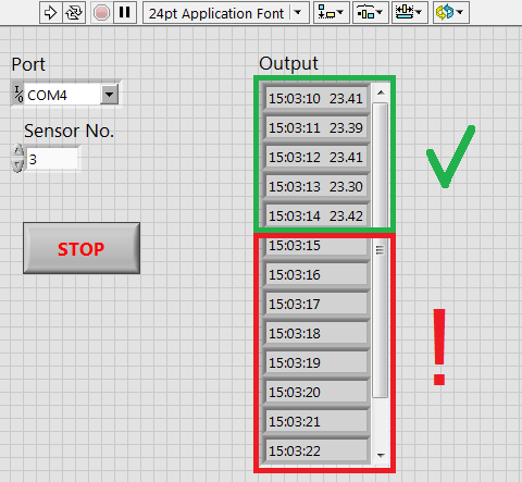
We turn on, wait for 20 seconds, stop ... And then the fun begins.
An array scan shows that the temperature is read only the first 5 times after starting the program, then only the time stamps without temperature readings:
I could not understand for a long time what the matter was - on the LV side, it would seem that there could not be an error, the block diagram to the disgrace is simple, the code of the Arduino sketch is also correct, because in the single manual polling mode works flawlessly. What else could be? Arduino board itself? After watching her, I discovered the following. We start the program, the LED L on pin 13 flashes twice, then the RX LED flashes (the controller has received the command for the temperature sensor sent by the PC), one second passes (the sensor converts the temperature into bytes in its memory, the PC waits for a response from it), blinks LED TX (the controller received bytes from the sensor and sent them to the PC), the RX diode flashes again, the second passes again, the TX flashes again, and so on in a circle until we stop the program. So, in my scheme, this kaleidoscope of lights lasted the first ~ 5 seconds, and then the controller stopped responding, the RX diode blinked continuously, and the program could only be stopped by the execution stop button in the LabVIEW interface.
All this confusion prompted me to think that somewhere there was something wrong with timing, and I began to dig in this direction, changed the waiting time in the VP, in the sketch, analyzed the code of the sketch literally along the line, the block diagram of the VP on Elementiku, but nothing helped. In the end, despairing gutted Send Receive.vi, because there was nowhere else to take the problem. Take a look at his block diagram:
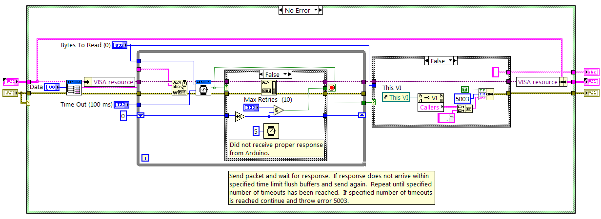
Send Receive, as it should, takes the data, sends it in the specified direction and takes a wait. If no response is received within 100 milliseconds, waits another 5 milliseconds, clears the output buffer and resends the data, up to 10 such attempts. Somewhere between the Send Receive, the microcontroller and the main VI in the process of work, an sync occurs and accumulates, and because of this, to the sixth iteration of the sensor polling, there is some discrepancy between the commands sent and the received, which hangs up the controller.
As experience shows, a simple-looking solution is not always the best, so I redid my DS18B20 Read.vi:
I admit honestly, I can not say exactly what was the matter, there is not enough depth of understanding of the interaction of the microcontroller with the PC. But as a result of my attempts, the problem disappeared, and I did not go into it.
Knowing how to read one sensor in auto mode, gash the reading of all five at once - a trick. To do this, I wrote another function in LabVIEWInterface.ino - OneWire_Read_All ():
As you can see, it, with minor changes, is a function of reading one sensor repeated 5 times.
We also had to slightly change the DS18B20 Read.vi - made it universal, both for polling individual sensors (it receives a number from 1 to 5) and for all at once (6 at the entrance). I also changed the number of bytes read from the buffer, because when polling all sensors immediately at the output of the VP, the line is almost 6 times longer, and increased the buffer polling interval:
Cheers, comrades! Everything works exactly the way I wanted.
It would seem that everything is ready, you can calm down, but with the tests all five sensors, being placed in the same conditions (a glass of water), gave slightly different readings. Therefore, they needed to be calibrated.
For this we needed: a mercury thermometer with a scale of 0.01 degrees Celsius, a laboratory stand with a pad, a glass, some ice from the freezer, an electric kettle and water. The improvised installation looked like this:
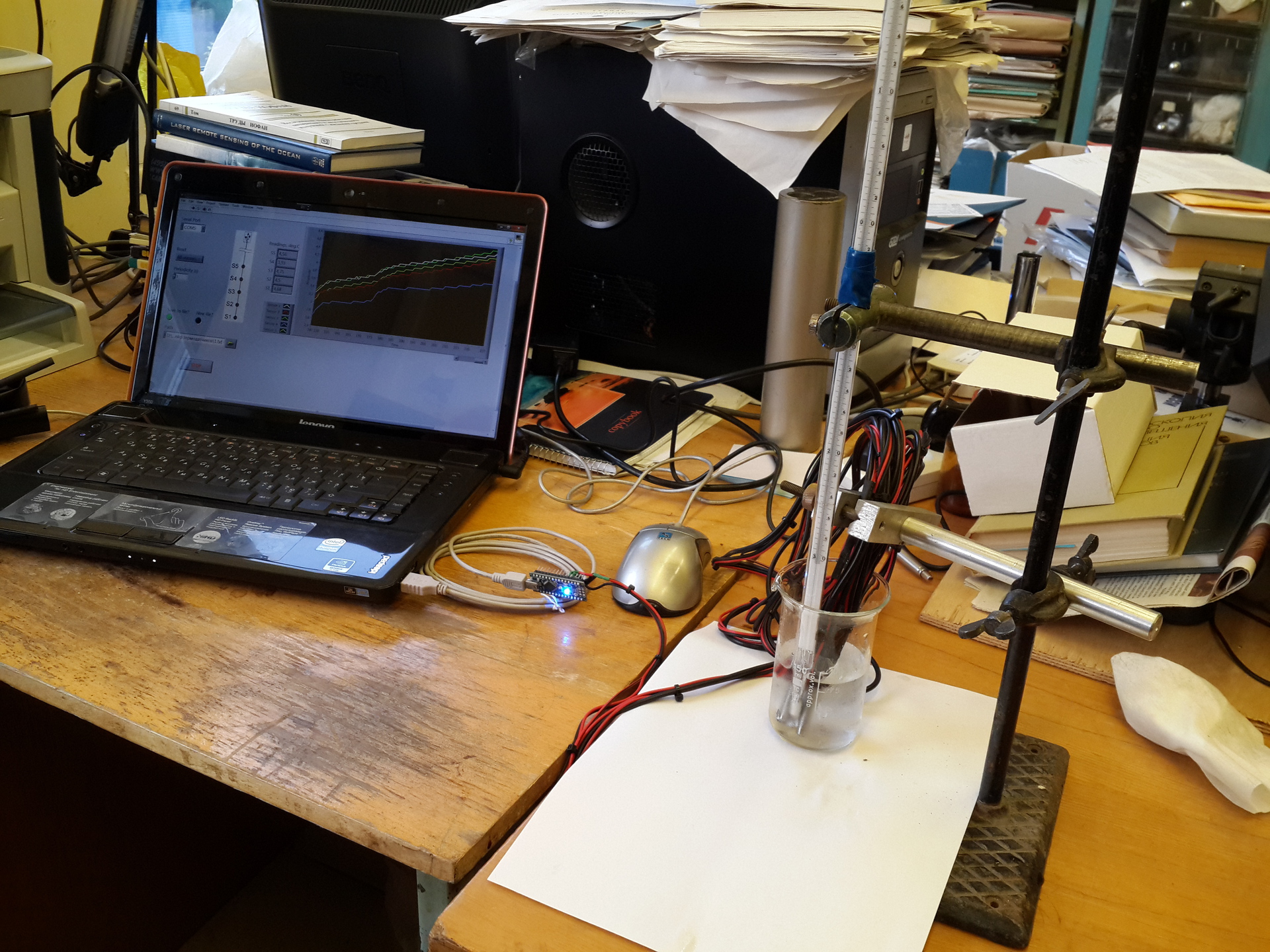
I apologize for the quality of the photos and for the mess in the laboratory.
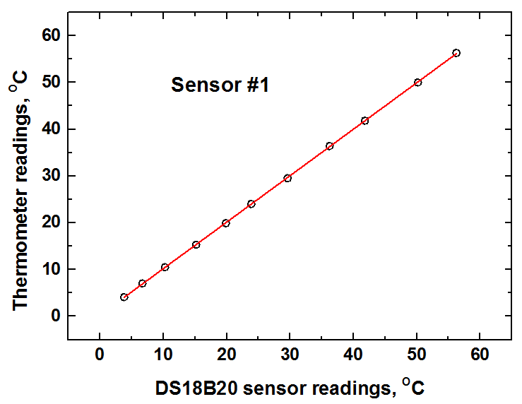
For several temperatures, the readings of the mercury thermometer and sensors were recorded, and calibration curves for each sensor were plotted.
As an example, the calibration curve for sensor No. 1.
According to the parameters of the curves obtained, I made calibration corrections to the data produced by the program.
Also with the help of the same “installation” in comparison of the readings of the sensors and the mercury thermometer, the error given by the thermowell was estimated. For different sensors at different temperatures, it is slightly different and averages 0.08 degrees Celsius.
The LIFA interface for working with Arduino provides a lot of possibilities - working with LCD displays, servo motors, IR control, etc., this is all useful, but in my case it is completely unnecessary, and therefore I rather radically cut LabVIEWInterface contents . ino , LIFA_BASE.ino , LabVIEWInterface.h and the LIFA_Base folders, removing all unnecessary from there. I will not give here listings, if someone wants to have a look, please contact, I will provide all the source codes with pleasure.
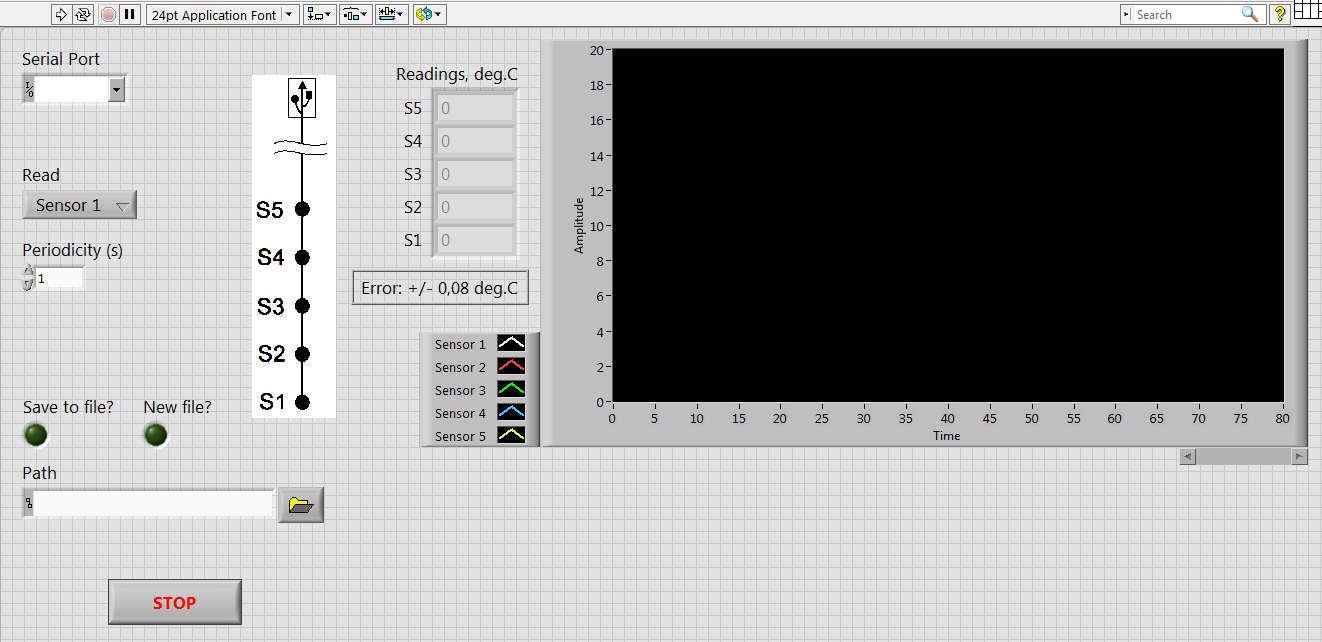
For the control program, I made this front panel:
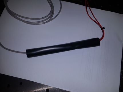
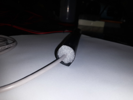
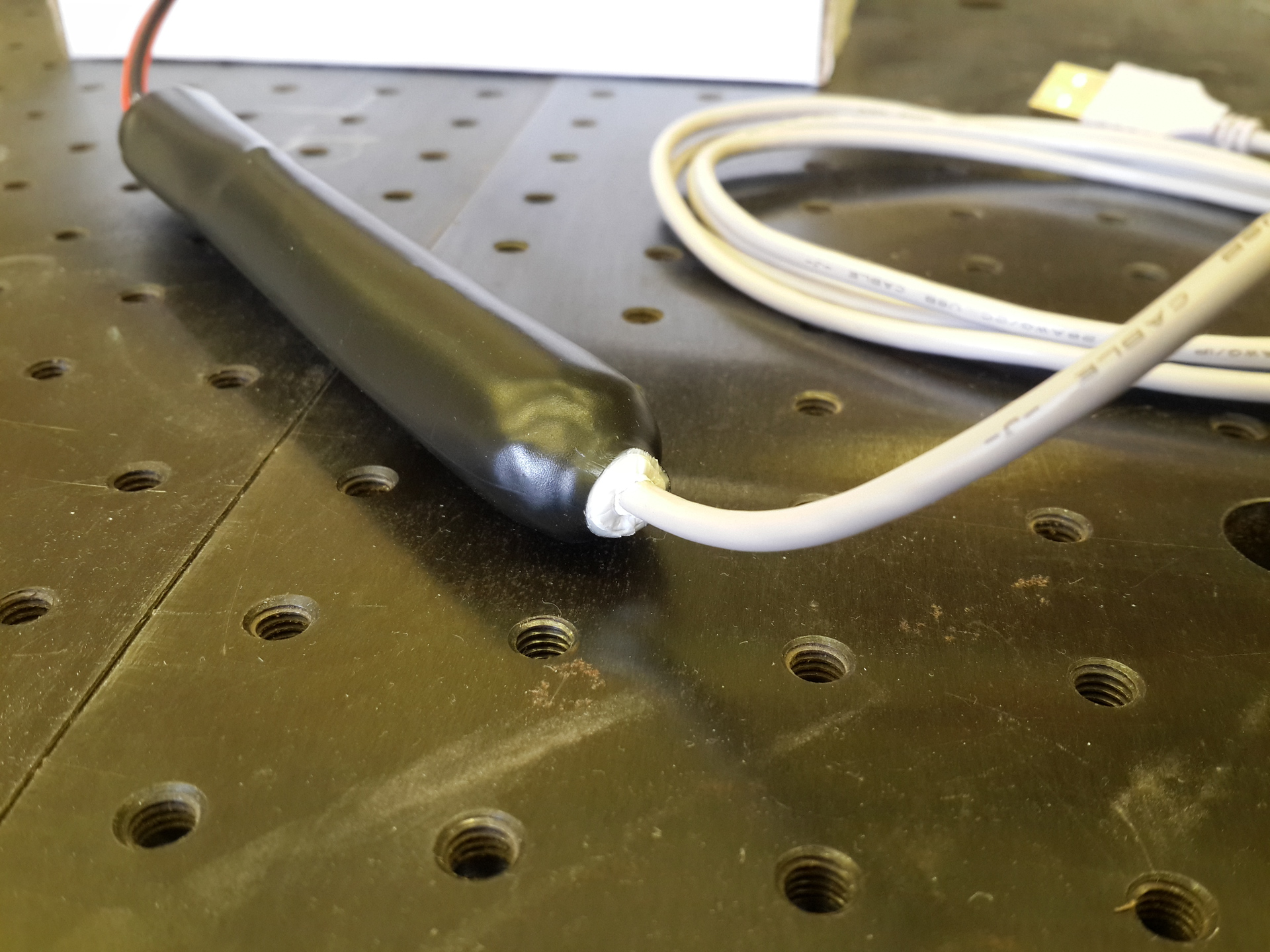
The Arduino shielding for environmental protection was packaged in a heat shrink tubing sealed from the ends:
The device is ready:

Cost of components and materials:
In total - 4200 rubles.
And now let's think. There are factory thermocowers for sale, it’s easy to google, for example, the “TC-10/10 thermocooder” with an average price of 13,000 rubles. You can ask: “And what for was it to steam, if there are analogues of industrial production of comparable cost, giving the same or negligible accuracy, obviously well-established, more reliable and high-quality?” I will answer for several reasons:
Thank you all for your attention! If you have any questions / suggestions / criticism, always happy to hear, the source codes of sketches and VI-shki provide with pleasure, as already mentioned above, please contact.
PS My programming skills are not far from “Hello world!”, So don’t judge strictly if I’ve used some terms inaccurately or not at all.
I work at the Institute of General Physics, RAS. The profile of our laboratory is laser remote sensing, specifically lidars. If you do not know what kind of animals, you can read, for example, on Wikipedia . Lidars are sometimes also called laser radars. The principal difference and advantage of lidar is that with its help one can not only measure the distance to the sensing object by the delay of the return signal, but also obtain (by the signal spectrum) information on the composition and properties of the object. For example, there are lidar methods for determining the temperature profile of water by depth in water bodies.
Non-contact measurements are only useful to the extent that they are accurate, therefore, to calibrate the results of remote measurements with contact measurements, it was decided to make a thermowax - a train of several thermal sensors on one line.
Iron
The contactless method using lidar makes it possible to measure the water temperature to a depth of several meters (it depends on transparency, it is clear that in dirty water the laser beam quickly dissipates and does not go far), therefore the thermowell is small, consists of five thermal sensors placed on the cable with an interval 1 m, plus another 4 m of cable, counting from the “upper” sensor.
')
I chose DS18B20 digital thermometers ( datasheet , 320 kb) in a sealed version as sensitive elements, such as:
Why precisely such? Because they are sealed (smile), they are already delivered with a cable of 1 m length, they provide high accuracy and work using the 1-Wire protocol, which greatly simplifies communication with them.
A thoughtful study of the datasheet gave the following information. Sensors can be connected in two ways: normal, via three wires (ground, “plus” power and signal bus) and in “stray” mode, when the sensor is powered from the data line. “Spurious” mode even more simplifies the connection (only two wires), but can sometimes distort the sensor readings. Any deterioration in accuracy is bad for us, and from the Arduino board that controls the sensors, 5 volts are easily accessible, so I decided to power the sensors in the usual way.
Thermal Mowers
Datashit recommends using a pull-up resistor of 4.7 kOhm, I only had two on the farm at 2.2, but this did not affect the performance of the device.
Arduino Nano with the ATMega328P controller is responsible for controlling the sensors and for communicating with the outside world, that is, with a PC.
Here is the scheme assembled on the breadboard:
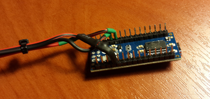
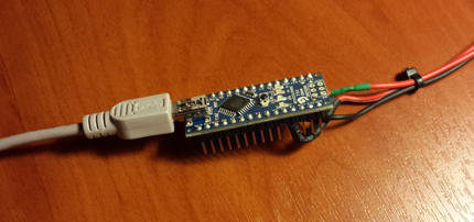
So - the final version after soldering and insulating:
And this is the entire assembly of the mower (the control electronics is not isolated):
I chose the Arduino as the “brains” of the device, firstly, because this platform is easy to learn, and secondly, because it can be controlled from a PC from under LabVIEW (hereafter LabVIEW = LV for short), which is important since the software of most of our laboratory’s projects is written in this environment, and the possibility of embedding a simple automated temperature control system in other schemes is expensive.
Soft
The main feature of this task is to work with the device from the LV environment; therefore, it was decided to start programming with studying the interaction of Arduino and LV. On Habré there is practically no information about this interaction, therefore, with your permission, I will describe everything in sufficient detail.
Start
So, what we need (information from here ):
- LV 2009 or newer.
- NI VISA (LV module for communicating virtual devices with real ones).
- Arduino IDE and drivers .
- OneWire library for Arduino - put the contents of the ZIPa in / [Arduino IDE installation directory] / libraries /.
- LV developer offers an extension for working with Arduino boards - LabVIEW Interface for Arduino, or simply LIFA. Since recently, the development of LIFA has been officially discontinued; instead, NI suggests using the LINV toolkit from LabVIEW Hacker. It supports a larger number of devices and contains more tools, however, I used LIFA, because LINX firmware controllers have the form of HEX files, which I didn’t have to do with disassembling and editing I had neither desire nor time. And in LIFA, the sources are the usual sketches for Arduino.
LIFA can be installed directly from LV through the Package Manager VI interface (Tools -> Package Manager VI). After installation, the Arduino palette appears on the function palette: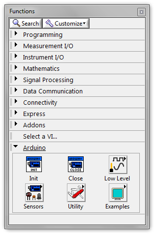
To start working with Arduino in LV, you need to flash your controller with the LIFA_Base.ino sketch taken from the C: / Program Files / National Instruments / LabVIEW [version] /vi.lib/LabVIEW Interface for Arduino / Firmware / LIFA_Base / folder. In this folder is a bunch of files - C-shnye libraries, sources and two sketches, LabVIEWInterface.ino and LIFA_Base.ino . The first contains descriptions of all the functions for working with Arduino, the second is very short and gathers everything together for uploading to the controller.
Voila, we now have access to most of the Arduino’s capabilities from the computer via LV. As you can guess, the first thing I did when I figured out everything described above was blinking with a LED.
Played, now for the cause.
The 1-Wire protocol and DS18B20 thermal sensors have been around for a long time and are widely distributed, so I decided to look for information on the sharing of DS18B20 and Arduino. And almost immediately I came across a suitable source, and not just anywhere, but on the official LabVIEW forum ( link ). Topikstarter had a similar task to me - to read the DS18B20 temperature sensor with Arduino from LabVIEW. He began searching and in a video clip on YouTube he saw the LV diagram with the OneWire Read VP present and asked the guru what kind of VP it was and where to get hold of it. The author of the video responded to his request and provided the source code and detailed instructions on how and what to do.
DS18B20 sensors are controlled as follows: the “master” (controller, microprocessor) sends a two-digit hexadecimal command through the data line, depending on which the sensor measures the temperature, receives bytes from the master to write to its memory, or sends the current contents of the memory to the data line . The author of the video modified the sketches that are uploaded to Arduino to work with LIFA:
- In the file LIFA_Base.ino connected the library OneWire.h,
- In the LabVIEWInterface.ino file in the case structure responsible for processing commands coming from LV over the serial bus, he added a variant 0x1E that calls the temperature reading function written by him:Code
case 0x1E: // OneWire Read OneWire_Read() break;
This function sends a 0x44 temperature measurement command (“conversion”) to the data line, waits for the conversion to finish, sends a 0xBE memory read command, reads, extracts the temperature reading from the received information and sends it to the serial bus:Codevoid OneWire_Read() { OneWire ds(2); // Create a OneWire Object "ds" on pin 2. Hard coding for now, because I can't declare this in a case. byte OneWireData[9]; // Defining stuff for the added OneWire function because I'm getting irritated with trying to make this fit into a case or function. int Fract, Whole, Tc_100, SignBit, TReading; // Start the Conversion ds.reset(); // Reset the OneWire bus in preparation for communication ds.skip(); // Skip addressing, since there is only one sensor ds.write(0x44); // Send 44, the conversion command // Wait for the Conversion delay(1000); // Wait for the conversion to complete // Read back the data ds.reset(); // Reset the OneWire bus in preparation for communication ds.skip(); // Skip addressing, since there is only one sensor ds.write(0xBE); // Send the "Read Scratchpad" command for ( byte i = 0; i < 9; i++) { OneWireData[i] = ds.read(); // Read the 9 bytes into data[] } // Scale the data TReading = (OneWireData[1] << 8) + OneWireData[0]; SignBit = TReading & 0x8000; // Mask out all but the MSB if (SignBit) // If the MSB is negative, take the Two's Compliment to make the reading negative { TReading = (TReading ^ 0xffff) + 1; // 2's comp } Tc_100 = (6 * TReading) + TReading / 4; // Scale by the sensitivity (0.0625°C per bit) and 100 Whole = Tc_100 / 100; // Split out the whole number portion of the reading Fract = Tc_100 % 100; // Split out the fractional portion of the reading // Return the data serially if (SignBit) { // If the reading is negative, print a negative sign Serial.print("-"); } Serial.print(Whole); // Print the whole number portion and a decimal Serial.print("."); if (Fract < 10) { // if the fraction portion is less than .1, append a 0 decimal Serial.print("0"); } Serial.print(Fract); // Otherwise print the fractional portion }
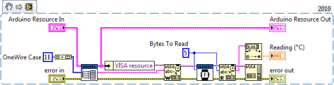
The proposed VP, in essence, merely sends the hexadecimal number 1E to the serial interface port indicated to it, waits for the answer and reads it:
It's pretty simple.
We read one sensor manually
First I edited LIFA_BASE.ino and LabVIEWInterface.ino in accordance with the instructions and made the VP. Checked, everything works, great. Then I did something that I later regretted. In the above topic on the LV forum, a couple of posts below one of the participants proposed his version of the VP, which reads the temperature sensor readings, consisting essentially of only one sub-device - Send Receive.vi from the Arduino subframe:
Being tempted by simplicity and not having penetrated into the details, in my further experiments I used this simple version without any doubt. No, no, everything is fine and good, it works correctly, however, there is a certain subtlety associated with the differences between my scenario of the sensor-Arduino-LabVIEW chain and the scenario for which the VP was made from the forum. This subtlety gave me a certain amount of headache later, but more on that later.
One of the features of the DS18B20 sensors is that each individual copy has its own unique 8-byte address (ROM code), wired into it during the production process. This theoretically allows you to hang an unlimited number of sensors on a single 1-Wire line. To implement this feature, an addressing command to a specific sensor is provided.
To be addressed, you need to know the address. I recognized the ROM codes of my sensors using the example of the DS18x20_Temperature from the OneWire library, and recorded them in five variables declared at the beginning of the program:
// DS18B20 temperature sensors' addresses: byte sensor_1[8] = {0x28,0xFF,0xBE,0xCE,0x14,0x14,0x00,0x8A}; byte sensor_2[8] = {0x28,0xFF,0x42,0x43,0x15,0x14,0x00,0xE2}; byte sensor_3[8] = {0x28,0xFF,0xED,0x55,0x15,0x14,0x00,0x8F}; byte sensor_4[8] = {0x28,0xFF,0x3D,0x6E,0x15,0x14,0x00,0x0D}; byte sensor_5[8] = {0x28,0xFF,0x5E,0x66,0x15,0x14,0x00,0x4E}; In the proposed version, OneWire_Read does not receive any values. Add a parameter to it - the address of the sensor (byte array of 8 elements):
void OneWire_Read(byte addr[8]) Before each sending of a command, we address the sensor:
// Start the Conversion ds.reset(); // Reset the OneWire bus in preparation for communication ds.select(addr); // Addressing ds.write(0x44); // Send 44, the conversion command // Read back the data ds.reset(); // Reset the OneWire bus in preparation for communication ds.select(addr); // Addressing ds.write(0xBE); // Send the "Read Scratchpad" command and add a variant to each sensor in the selection structure:
/********************************************************************************* ** OneWire temperature sensors reading *********************************************************************************/ case 0x2E: // sensor 1 read OneWire_Read(sensor_1); break; case 0x2F: // sensor 2 read OneWire_Read(sensor_2); break; case 0x30: // sensor 3 read OneWire_Read(sensor_3); break; case 0x31: // sensor 4 read OneWire_Read(sensor_4); break; case 0x32: // sensor 5 read OneWire_Read(sensor_5); break; To test what happened, I made my small VI for a single poll of one sensor:
As you can see, I implemented the choice of the sensor for the survey through the case-structure in the block diagram.
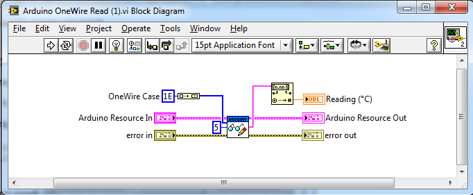
For the convenience of future use, I made a small runway, as shown in the screenshot below, was
Apart from the Arduino resource clusters and errors, the runway receives the sensor number for polling and the output reads the temperature as a string.
Hooray! The tests were successful.
We read one sensor in automatic mode
Well, we now know how to manually poll one sensor. The next step is a cyclical survey of one sensor in automatic mode. For this, I made the following block diagram:
To begin with, the interval is fixed, the program polls the sensor once a second, and after the cycle is stopped, the user writes the collected data to the array. For convenience, I added a time stamp to each temperature reading using the Get Date / Time String function.
We turn on, wait for 20 seconds, stop ... And then the fun begins.
An array scan shows that the temperature is read only the first 5 times after starting the program, then only the time stamps without temperature readings:
I could not understand for a long time what the matter was - on the LV side, it would seem that there could not be an error, the block diagram to the disgrace is simple, the code of the Arduino sketch is also correct, because in the single manual polling mode works flawlessly. What else could be? Arduino board itself? After watching her, I discovered the following. We start the program, the LED L on pin 13 flashes twice, then the RX LED flashes (the controller has received the command for the temperature sensor sent by the PC), one second passes (the sensor converts the temperature into bytes in its memory, the PC waits for a response from it), blinks LED TX (the controller received bytes from the sensor and sent them to the PC), the RX diode flashes again, the second passes again, the TX flashes again, and so on in a circle until we stop the program. So, in my scheme, this kaleidoscope of lights lasted the first ~ 5 seconds, and then the controller stopped responding, the RX diode blinked continuously, and the program could only be stopped by the execution stop button in the LabVIEW interface.
All this confusion prompted me to think that somewhere there was something wrong with timing, and I began to dig in this direction, changed the waiting time in the VP, in the sketch, analyzed the code of the sketch literally along the line, the block diagram of the VP on Elementiku, but nothing helped. In the end, despairing gutted Send Receive.vi, because there was nowhere else to take the problem. Take a look at his block diagram:
Send Receive, as it should, takes the data, sends it in the specified direction and takes a wait. If no response is received within 100 milliseconds, waits another 5 milliseconds, clears the output buffer and resends the data, up to 10 such attempts. Somewhere between the Send Receive, the microcontroller and the main VI in the process of work, an sync occurs and accumulates, and because of this, to the sixth iteration of the sensor polling, there is some discrepancy between the commands sent and the received, which hangs up the controller.
As experience shows, a simple-looking solution is not always the best, so I redid my DS18B20 Read.vi:
I admit honestly, I can not say exactly what was the matter, there is not enough depth of understanding of the interaction of the microcontroller with the PC. But as a result of my attempts, the problem disappeared, and I did not go into it.
We read all sensors in automatic mode
Knowing how to read one sensor in auto mode, gash the reading of all five at once - a trick. To do this, I wrote another function in LabVIEWInterface.ino - OneWire_Read_All ():
Code
void OneWire_Read_All() { OneWire ds(2); byte Data[9]; int Fract, Whole, Tc_100, SignBit, TReading; ds.reset(); ds.skip(); // Addressing to all sensors on the line ds.write(0x44); delay(1000); // reading sensor 1 ds.reset(); ds.select(sensor_1); // Addressing to sensor 1 ds.write(0xBE); for ( byte i = 0; i < 9; i++) { Data[i] = ds.read(); } TReading = (Data[1] << 8) + Data[0]; SignBit = TReading & 0x8000; if (SignBit) { TReading = (TReading ^ 0xffff) + 1; } Tc_100 = (6 * TReading) + TReading / 4; Whole = Tc_100 / 100; Fract = Tc_100 % 100; if (SignBit) { Serial.print("-"); } Serial.print(Whole); Serial.print(","); if (Fract < 10) { Serial.print("0"); } Serial.print(Fract); Serial.print(" "); // reading sensor 2 ds.reset(); ds.select(sensor_2); // Addressing to sensor 2 ds.write(0xBE); for ( byte i = 0; i < 9; i++) { Data[i] = ds.read(); } TReading = (Data[1] << 8) + Data[0]; SignBit = TReading & 0x8000; if (SignBit) { TReading = (TReading ^ 0xffff) + 1; } Tc_100 = (6 * TReading) + TReading / 4; Whole = Tc_100 / 100; Fract = Tc_100 % 100; if (SignBit) { Serial.print("-"); } Serial.print(Whole); Serial.print(","); if (Fract < 10) { Serial.print("0"); } Serial.print(Fract); Serial.print(" "); // reading sensor 3 ds.reset(); ds.select(sensor_3); // Addressing to sensor 3 ds.write(0xBE); for ( byte i = 0; i < 9; i++) { Data[i] = ds.read(); } TReading = (Data[1] << 8) + Data[0]; SignBit = TReading & 0x8000; if (SignBit) { TReading = (TReading ^ 0xffff) + 1; } Tc_100 = (6 * TReading) + TReading / 4; Whole = Tc_100 / 100; Fract = Tc_100 % 100; if (SignBit) { Serial.print("-"); } Serial.print(Whole); Serial.print(","); if (Fract < 10) { Serial.print("0"); } Serial.print(Fract); Serial.print(" "); // reading sensor 4 ds.reset(); ds.select(sensor_4); // Addressing to sensor 4 ds.write(0xBE); for ( byte i = 0; i < 9; i++) { Data[i] = ds.read(); } TReading = (Data[1] << 8) + Data[0]; SignBit = TReading & 0x8000; if (SignBit) { TReading = (TReading ^ 0xffff) + 1; } Tc_100 = (6 * TReading) + TReading / 4; Whole = Tc_100 / 100; Fract = Tc_100 % 100; if (SignBit) { Serial.print("-"); } Serial.print(Whole); Serial.print(","); if (Fract < 10) { Serial.print("0"); } Serial.print(Fract); Serial.print(" "); // reading sensor 5 ds.reset(); ds.select(sensor_5); // Addressing to sensor 5 ds.write(0xBE); for ( byte i = 0; i < 9; i++) { Data[i] = ds.read(); } TReading = (Data[1] << 8) + Data[0]; SignBit = TReading & 0x8000; if (SignBit) { TReading = (TReading ^ 0xffff) + 1; } Tc_100 = (6 * TReading) + TReading / 4; Whole = Tc_100 / 100; Fract = Tc_100 % 100; if (SignBit) { Serial.print("-"); } Serial.print(Whole); Serial.print(","); if (Fract < 10) { Serial.print("0"); } Serial.print(Fract); } As you can see, it, with minor changes, is a function of reading one sensor repeated 5 times.
We also had to slightly change the DS18B20 Read.vi - made it universal, both for polling individual sensors (it receives a number from 1 to 5) and for all at once (6 at the entrance). I also changed the number of bytes read from the buffer, because when polling all sensors immediately at the output of the VP, the line is almost 6 times longer, and increased the buffer polling interval:
Cheers, comrades! Everything works exactly the way I wanted.
Calibration
It would seem that everything is ready, you can calm down, but with the tests all five sensors, being placed in the same conditions (a glass of water), gave slightly different readings. Therefore, they needed to be calibrated.
For this we needed: a mercury thermometer with a scale of 0.01 degrees Celsius, a laboratory stand with a pad, a glass, some ice from the freezer, an electric kettle and water. The improvised installation looked like this:
I apologize for the quality of the photos and for the mess in the laboratory.
For several temperatures, the readings of the mercury thermometer and sensors were recorded, and calibration curves for each sensor were plotted.
As an example, the calibration curve for sensor No. 1.
According to the parameters of the curves obtained, I made calibration corrections to the data produced by the program.
Also with the help of the same “installation” in comparison of the readings of the sensors and the mercury thermometer, the error given by the thermowell was estimated. For different sensors at different temperatures, it is slightly different and averages 0.08 degrees Celsius.
Finishing touches
The LIFA interface for working with Arduino provides a lot of possibilities - working with LCD displays, servo motors, IR control, etc., this is all useful, but in my case it is completely unnecessary, and therefore I rather radically cut LabVIEWInterface contents . ino , LIFA_BASE.ino , LabVIEWInterface.h and the LIFA_Base folders, removing all unnecessary from there. I will not give here listings, if someone wants to have a look, please contact, I will provide all the source codes with pleasure.
For the control program, I made this front panel:
The Arduino shielding for environmental protection was packaged in a heat shrink tubing sealed from the ends:
The device is ready:
Results
Cost of components and materials:
- Arduino Nano - 1900 rubles;
- 5 DS18B20 thermal sensors - 1950 rubles;
- 10 m cable - 150 rubles;
- Little things (shrinking, cable ties, ...) - 200 rubles;
In total - 4200 rubles.
And now let's think. There are factory thermocowers for sale, it’s easy to google, for example, the “TC-10/10 thermocooder” with an average price of 13,000 rubles. You can ask: “And what for was it to steam, if there are analogues of industrial production of comparable cost, giving the same or negligible accuracy, obviously well-established, more reliable and high-quality?” I will answer for several reasons:
- / * Speaking not about serious scientific equipment, but about devices like the one described above. * / When buying a ready-made solution, you have to believe the numbers of the characteristics that the manufacturer indicated. This is normal when using the device in production or at home, but not for scientific purposes. I’m not saying that the manufacturer deliberately gives false information, but, as a rule, you don’t know anything about the intricacies of the internal device, methods of estimating the parameters of the device used in its manufacture, and they may turn out to be inaccurate or contain inappropriate assumptions. In general, you understand the main principle of the scientific worldview - "Do not take anything for granted." Another thing is if you assemble the device yourself literally by the detail, you yourself set the logic of its work and evaluate its accuracy according to the methods chosen by you.
- From an educational point of view, making thermocouples brought valuable experience with a soldering iron, programming the Arduino, and understanding its connection to a computer through LabVIEW, especially in light of the fact that I continue to study the Arduino-LV-PC bundle in a project that I switched to when I finished.
- To a lesser extent, but the question of value also mattered.
Thank you all for your attention! If you have any questions / suggestions / criticism, always happy to hear, the source codes of sketches and VI-shki provide with pleasure, as already mentioned above, please contact.
PS My programming skills are not far from “Hello world!”, So don’t judge strictly if I’ve used some terms inaccurately or not at all.
Source: https://habr.com/ru/post/242377/
All Articles