FLProg is an alternative Arduino programming environment. Project Description
In a previous post, I talked about the background history of the FLProg project. Now I want to talk in more detail about the project and its state to date.
The main goal of the project is to include people unfamiliar with programming in the circle of users of the Arduino boards. This is possible thanks to the experience of industrial programming, which has been accumulated over the years by manufacturers of industrial controllers.
The project consists of two parts. The first part is the desktop FLProg application, which is a graphical programming environment for Arduino boards. Secondly, this is the FLProg.ru website, through which members of the user community of the program can communicate with each other, find out the latest project news, download the latest version of the program, and find the necessary information on working with the application.
Let's start in order.
The FLProg program allows you to create firmware for Arduino boards using FBD and LAD graphic languages, which are the standard in the field of programming industrial controllers.
FBD language description
FBD (Function Block Diagram) is a graphical programming language of the IEC 61131-3 standard. The program is formed from a list of chains running sequentially from top to bottom. Programming uses sets of library blocks. A block (element) is a subroutine, function or function block (AND, OR, NOT, triggers, timers, counters, analog signal processing units, mathematical operations, etc.). Each individual chain is an expression composed graphically of individual elements. The next block is connected to the output of the block, forming a circuit. Inside the chain, the blocks are executed strictly in the order of their connection. The result of the calculation of the circuit is recorded in the internal variable or fed to the output of the controller.
LAD Language Description
Ladder Diagram (LD, LAD, ) - language of relay (ladder) logic. The syntax of the language is convenient for replacing logic circuits made on the relay technology. The language is aimed at automation engineers working in industrial enterprises. Provides a visual interface of the controller logic, which facilitates not only the tasks of programming and commissioning itself, but also a quick troubleshooting of the equipment connected to the controller. The program in relay logic language has a visual and intuitively understandable to electrical engineers a graphical interface representing logical operations, like an electrical circuit with closed and open contacts. The flow or absence of current in this circuit corresponds to the result of a logical operation (true - if the current flows; false - if the current does not flow). The main elements of the language are contacts that can be figuratively likened to a pair of relay contacts or buttons. A pair of contacts is identified with a logical variable, and the state of this pair is identified with the value of the variable. Normally closed and normally open contact elements, which can be compared with normally closed and normally open buttons in electrical circuits, are distinguished.
I have slightly expanded the classic functionality of these languages by adding functional blocks responsible for working with external devices. They are wrappers for libraries designed to work with them.
A project in FLProg is a collection of boards, on each of which a complete module of the general scheme is assembled. For convenience, each board has a name and comments. Also, each board can be minimized (to save space in the work area when work on it is completed), and deploy. A red indicator in the name of the board indicates that there are errors in the circuit board.
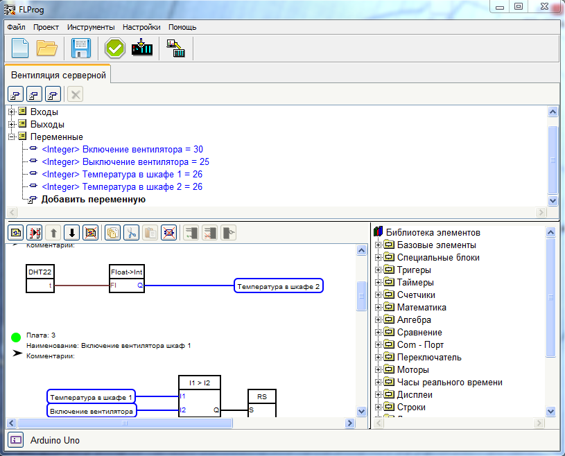
View of the program window in FBD language mode
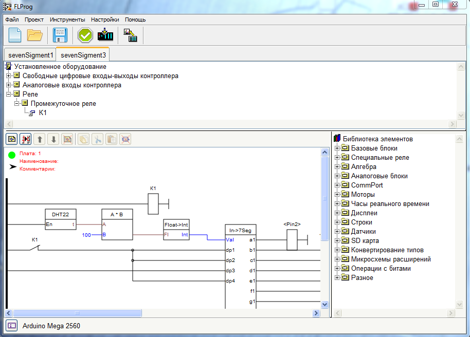
View of the program window in LAD language mode
')
The layout of each board is assembled from functional blocks in accordance with the logic of the controller. Most function blocks have the ability to customize, with which their work can be configured in accordance with the requirements in this particular case.
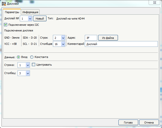
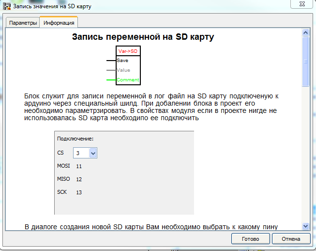
There is also a detailed description for each functional block, which is available at any time and helps to understand its work and settings.
When working with the program, the user does not need to write code, control the use of inputs and outputs, check the uniqueness of names and consistency of data types. The program is following all this. She also verifies the correctness of the project as a whole and indicates the presence of errors.
To work with external devices created several auxiliary tools. It is a tool for initializing and setting the real-time clock, tools for reading the addresses of devices on OneWire and I2C buses, as well as a tool for reading and saving codes of buttons on the IR remote control. All specific data can be saved as a file and later used in the program.
The list of functional blocks existing today in the FBD language
[XOR]
[AND]
[OR]
[Bounce]
[Scale]
[SR]
[TT]
[RS]
[Rtrig]
[Generator]
[Timer]
[Counter]
[SpeedCounter]
[SUM (+)]
[MUL (*)]
[DIV (/)]
[SUB (-)]
[SIN]
[COS]
[TAN]
[ABS]
[SQ]
[Sqrt]
[MIN]
[MAX]
[POW]
[RANDOM]
[Comparator]
Send
Sendvariable
ReceiveVariable
[SWITCH]
[MUX]
[DMS]
ServoMotor
Step motor
[Alarm]
[Gettime]
[SetTime]
Display on HD44780 chip
Illumination of the display on the HD44780 I2C chip
Seven Segment Indicator Decoding Unit
Addition of lines
[Ultrasonic HC-SR04]
[DHT11, DHT21, DHT22]
[DS18x2x]
[IR ressive]
[BMP-085]
Write variable to SD card
Uploading a file from an SD card
String conversion
Convert Float to Integer
74HC595 Pin Extender
Encoder
Decoder
Bit reading
Write bit
Matrix keyboard
Basic elements
[XOR]
[AND]
[OR]
[Bounce]
Special blocks
[Scale]
Triggers
[SR]
[TT]
[RS]
[Rtrig]
Timers
[Generator]
[Timer]
Counters
[Counter]
[SpeedCounter]
Maths
[SUM (+)]
[MUL (*)]
[DIV (/)]
[SUB (-)]
Algebra
[SIN]
[COS]
[TAN]
[ABS]
[SQ]
[Sqrt]
[MIN]
[MAX]
[POW]
[RANDOM]
Comparison
[Comparator]
Com - Port
Send
Sendvariable
ReceiveVariable
Switch
[SWITCH]
[MUX]
[DMS]
Motors
ServoMotor
Step motor
Real time clock
[Alarm]
[Gettime]
[SetTime]
Displays
Display on HD44780 chip
Illumination of the display on the HD44780 I2C chip
Seven Segment Indicator Decoding Unit
Strings
Addition of lines
Sensors
[Ultrasonic HC-SR04]
[DHT11, DHT21, DHT22]
[DS18x2x]
[IR ressive]
[BMP-085]
SD card
Write variable to SD card
Uploading a file from an SD card
Type conversion
String conversion
Convert Float to Integer
Extensions Chips
74HC595 Pin Extender
Bit operations
Encoder
Decoder
Bit reading
Write bit
miscellanea
Matrix keyboard
The list of functional blocks existing today in the LAD language
Contact
Coil
Chatter protection
Front Achievement
Two Stable Relay
Time relay
Generator
Comparison relay
Sin
Cos
Tan
ABS
MAX
MIN
SQ
Sqrt
POW
Random
Scaling
Maths
Counter
Analog switch
Switch many to one
One to many switch
Analog input controller
Analog output controller
Analog Connector Input
Analog connector output
Speed counter
Transfer to ComPort
Passing a variable through ComPort
Receiving a variable through ComPort
Servomotor
Stepper motor
To get data
Alarm clock
Time setting
HD44780 display
The control unit backlight display on the chip HD4480 I2C
Seven Segment Indicator Decoding Unit
Addition of lines
Ultrasonic Range Finder HC-SR04
Temperature and humidity sensor DHT11 (DHT21, DHT22)
DS18x2x temperature sensor
IR ressive
BMP-085
Write variable to SD card
Uploading a file from an SD card
String conversion
Convert Float to Integer
74HC595 Pin Extender
Encoder
Decoder
Bit reading
Write bit
Matrix keyboard.
Base blocks
Contact
Coil
Chatter protection
Front Achievement
Special relays
Two Stable Relay
Time relay
Generator
Comparison relay
Algebra
Sin
Cos
Tan
ABS
MAX
MIN
SQ
Sqrt
POW
Random
Analog blocks
Scaling
Maths
Counter
Analog switch
Switch many to one
One to many switch
Analog input controller
Analog output controller
Analog Connector Input
Analog connector output
Speed counter
Comport
Transfer to ComPort
Passing a variable through ComPort
Receiving a variable through ComPort
Motors
Servomotor
Stepper motor
Real time clock
To get data
Alarm clock
Time setting
Displays
HD44780 display
The control unit backlight display on the chip HD4480 I2C
Seven Segment Indicator Decoding Unit
Strings
Addition of lines
Sensors
Ultrasonic Range Finder HC-SR04
Temperature and humidity sensor DHT11 (DHT21, DHT22)
DS18x2x temperature sensor
IR ressive
BMP-085
SD card
Write variable to SD card
Uploading a file from an SD card
Type conversion
String conversion
Convert Float to Integer
Extensions Chips
74HC595 Pin Extender
Bit operations
Encoder
Decoder
Bit reading
Write bit
miscellanea
Matrix keyboard.
The list of equipment used in the project today.
DS1302
DS1307
DS3231
Temperature and humidity sensor DHT11
Temperature and humidity sensor DHT21
Temperature and humidity sensor DHT22
Ultrasonic Range Finder HC-SR04
DS18B20 Temperature Sensors
DS18S20 Temperature Sensors
DS1822 temperature sensors
BMP085 pressure sensor
Motion Sensor (PIR Motion Sensor) HC-SR501
MQ2 gas sensor (hydrocarbon gases, smoke).
Stepper motor
Servo
HD44780 Chip Display with Parallel Control and I2C Bus Control
Seven segment indicators
SD card reader.
Shift Registers 74HC595
Matrix keyboard
Real time clock
DS1302
DS1307
DS3231
Sensors
Temperature and humidity sensor DHT11
Temperature and humidity sensor DHT21
Temperature and humidity sensor DHT22
Ultrasonic Range Finder HC-SR04
DS18B20 Temperature Sensors
DS18S20 Temperature Sensors
DS1822 temperature sensors
BMP085 pressure sensor
Motion Sensor (PIR Motion Sensor) HC-SR501
MQ2 gas sensor (hydrocarbon gases, smoke).
Motors
Stepper motor
Servo
Displays
HD44780 Chip Display with Parallel Control and I2C Bus Control
Seven segment indicators
miscellanea
SD card reader.
Shift Registers 74HC595
Matrix keyboard
In the following publications I will talk about the project site and the prospects for the development of the project.
Source: https://habr.com/ru/post/242335/
All Articles