FPGA Clock (VHDL)
At this stage of training, I was pushed to access this design by the Altera EP2C20F484C7 debug board (the Cyclone-II family).
The FPGA features that allow you to turn it into an integrated circuit with any function of digital logic. Design comes down to the identification of programmable elements (jumpers or storage cells), after removal of which only those connections that are necessary to perform the required functions remain in the circuit structure. In practice, this task is very difficult, as modern FPGAs contain on average several tens of thousands of jumpers. Therefore, for the design must necessarily use computer-aided design (CAD FPGA).
When developing original equipment, as well as to replace conventional electronic circuits with small and medium degree of integration. This significantly reduces the size of the device, reduces power consumption and increases reliability. The most effective use of FPGAs in products that require non-standard circuit solutions. Designing a digital clock on the FPGA allows you to reduce the time spent on debugging. The number of elements used, integrated circuits, and memory blocks.
The whole process of creating watches comes down to the following item:
')
1. Selecting the FPGA model.
2. Writing the FPGA control program using the VHDL language tool.
3. Debugging of the program on the debug stand.
4. Creation of the concept of batteries and display.
Functional diagram
The functional part of the clock is shown in Figure 1, where hours and minutes or minutes and seconds are displayed on four seven segment indicators, depending on the state of the “Other” button.
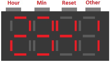
The "Reset" button is designed to reset the seconds counter, depending on its value, if more than 30, then 1 minute is added and seconds are reset, and if it is less, seconds are simply reset. The “Hour” and “Min” buttons are used to set the clock (by pressing).
Also, to implement the clock, you will need a crystal oscillator which is designed to get a fixed frequency with high temperature and time stability, low phase noise, frequency stability of about (10-5 -10-12).
When drawing up the structural scheme of Figure 2, we take into account that the user should be able to reset the seconds, set the hours and minutes, and the display mode of the two options hour / min or min / sec.
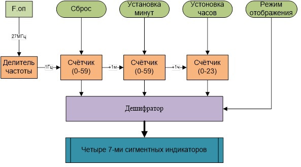
When designing, it was decided to use a quartz pulse generator with a frequency of 27 MHz. Since the current frequency guarantees a high accuracy of seconds.
From quartz, a signal is sent to a divider block, which in turn converts a signal with a frequency of 27 MHz into a clock signal of the square wave with a frequency of 1 Hz. Which in turn means that one oscillation period will pass in 1 second.
Then the signal from the divider is fed to the first counter (seconds counter), to which the reset command also arrives, the counter analyzes the inputs, and produces a count of 0 to 59. Each clock cycle, sending its state to the decoder. When it reaches 59 (maximum of the account), or if “Reset” was pressed when the status of the account is greater than or equal to 30, it sends a square-wave clock to the watched counter.
The second counter (minute counter) works in the same way as the first one, except that the signal to the input is not “Reset” but “Min” (setting minutes). As a result, 1 is added once to the current state of the account, which contributes to an increase in the account.
The third counter (clock counter), receiving a signal from the led counter and from the “Hour” (Setting the clock), counts from 0 to 23. Each bill sends the counter values to the decoder.
By processing the signal from the “Other” button (display mode), the decoder selects the required input signals: for min / sec it selects the values of the first and second counters, for hours / min selects the values of the second and third counters. It decrypts them and then encrypts the necessary signal to display the time numbers on a block of four 7 segment indicators.
When developing a program on VHDL, it was decided to use the structure using components. That allows us to write a program to execute each block of the structural scheme separately, it is also possible to combine several blocks into one component. Note that the pressed position of the button is '0' and the pressed one is '1'.
Consider a component called timeMS, it is a universal component; it is used for the seconds and minutes counter, as they seem to be.
First, we declare the necessary packages, descriptions of the packages used. Then go to the description of the ports. As it was said earlier, this program combines two counters, as a result, input ports for both the minutes counter and the seconds counter.
Input ports of the program:
- Port “C” - takes two values ('0' and '1') and is intended for setting minutes.
- Port “R” - takes two values ('0' and '1') and is designed to reset seconds.
- The “clk” port is a square wave clock signal, for seconds from the divider (see additions delitel), for minutes the signal from the leading seconds counter.
Input ports of the program:
- Port “M” - takes two values ('0' and '1'), sends a clock signal when the maximum is reached, to the next counter.
- Port “hex” - 6-bit vector for sending the state of the counter to the decoder (component hexMS, see addition).
The process is “sensitive” to signal changes: clk, C, R. It is also a process with asynchronous reset, in the case of seconds, and asynchronous addition to the account +1 in the case of minutes. For the account, the nex variable of type integer from 0 to 59 is used.
At the beginning of the process, the signal of the clock pulse and the signal from the “Min” button are added, then it is checked:
“Reset” = '0' conditions are verified, current values of the account are greater than 29 if not, then just reset, otherwise reset and send '1' to port M.
"Reset" = '1' checks whether the leading edge of the clock pulse has come. Then check the condition of filling the counter, and write to it +1.
At the end of the program, the values of the nex variable are converted and sent to the hex port.
The FPGA features that allow you to turn it into an integrated circuit with any function of digital logic. Design comes down to the identification of programmable elements (jumpers or storage cells), after removal of which only those connections that are necessary to perform the required functions remain in the circuit structure. In practice, this task is very difficult, as modern FPGAs contain on average several tens of thousands of jumpers. Therefore, for the design must necessarily use computer-aided design (CAD FPGA).
In which cases it is advisable to use FPGA?
When developing original equipment, as well as to replace conventional electronic circuits with small and medium degree of integration. This significantly reduces the size of the device, reduces power consumption and increases reliability. The most effective use of FPGAs in products that require non-standard circuit solutions. Designing a digital clock on the FPGA allows you to reduce the time spent on debugging. The number of elements used, integrated circuits, and memory blocks.
The whole process of creating watches comes down to the following item:
')
1. Selecting the FPGA model.
2. Writing the FPGA control program using the VHDL language tool.
3. Debugging of the program on the debug stand.
4. Creation of the concept of batteries and display.
Functional diagram
The functional part of the clock is shown in Figure 1, where hours and minutes or minutes and seconds are displayed on four seven segment indicators, depending on the state of the “Other” button.
The "Reset" button is designed to reset the seconds counter, depending on its value, if more than 30, then 1 minute is added and seconds are reset, and if it is less, seconds are simply reset. The “Hour” and “Min” buttons are used to set the clock (by pressing).
Also, to implement the clock, you will need a crystal oscillator which is designed to get a fixed frequency with high temperature and time stability, low phase noise, frequency stability of about (10-5 -10-12).
Block diagram of the clock and a description of its work
When drawing up the structural scheme of Figure 2, we take into account that the user should be able to reset the seconds, set the hours and minutes, and the display mode of the two options hour / min or min / sec.
When designing, it was decided to use a quartz pulse generator with a frequency of 27 MHz. Since the current frequency guarantees a high accuracy of seconds.
From quartz, a signal is sent to a divider block, which in turn converts a signal with a frequency of 27 MHz into a clock signal of the square wave with a frequency of 1 Hz. Which in turn means that one oscillation period will pass in 1 second.
Then the signal from the divider is fed to the first counter (seconds counter), to which the reset command also arrives, the counter analyzes the inputs, and produces a count of 0 to 59. Each clock cycle, sending its state to the decoder. When it reaches 59 (maximum of the account), or if “Reset” was pressed when the status of the account is greater than or equal to 30, it sends a square-wave clock to the watched counter.
The second counter (minute counter) works in the same way as the first one, except that the signal to the input is not “Reset” but “Min” (setting minutes). As a result, 1 is added once to the current state of the account, which contributes to an increase in the account.
The third counter (clock counter), receiving a signal from the led counter and from the “Hour” (Setting the clock), counts from 0 to 23. Each bill sends the counter values to the decoder.
By processing the signal from the “Other” button (display mode), the decoder selects the required input signals: for min / sec it selects the values of the first and second counters, for hours / min selects the values of the second and third counters. It decrypts them and then encrypts the necessary signal to display the time numbers on a block of four 7 segment indicators.
Development of the project, hours in the VHDL language
When developing a program on VHDL, it was decided to use the structure using components. That allows us to write a program to execute each block of the structural scheme separately, it is also possible to combine several blocks into one component. Note that the pressed position of the button is '0' and the pressed one is '1'.
Consider a component called timeMS, it is a universal component; it is used for the seconds and minutes counter, as they seem to be.
Library ieee;
use ieee.std_logic_1164.all;
use ieee.std_logic_unsigned.all;
use ieee.std_logic_arith.all;
Entity timeMS is
Port
(
C: in std_logic; - +1 minute
R: in std_logic; - reset use for sec.
clk: in std_logic; - clock signal 1 sec.
M: out std_logic; - pass +1 further
hex: out std_logic_vector (0 to 5) - output to seven-bit indicator
);
end timeMS;
Architecture behavior of timeMS is
signal cl: std_logic;
begin
Process (clk, R, C)
Variable nex: integer range 0 to 59;
begin
cl <= clk or not;
if R = '0'then
if nex> 29 then
M <= '1';
nex: = 0;
else
M <= '0';
nex: = 0;
end if;
else
if (cl'event and cl = '1') then
if nex = 59 then
nex: = 0;
M <= '1';
else
nex: = nex + 1;
M <= '0';
end if;
end if;
end if;
hex <= conv_std_logic_vector (nex, 6);
end process;
end behavior;
First, we declare the necessary packages, descriptions of the packages used. Then go to the description of the ports. As it was said earlier, this program combines two counters, as a result, input ports for both the minutes counter and the seconds counter.
Input ports of the program:
- Port “C” - takes two values ('0' and '1') and is intended for setting minutes.
- Port “R” - takes two values ('0' and '1') and is designed to reset seconds.
- The “clk” port is a square wave clock signal, for seconds from the divider (see additions delitel), for minutes the signal from the leading seconds counter.
Input ports of the program:
- Port “M” - takes two values ('0' and '1'), sends a clock signal when the maximum is reached, to the next counter.
- Port “hex” - 6-bit vector for sending the state of the counter to the decoder (component hexMS, see addition).
The process is “sensitive” to signal changes: clk, C, R. It is also a process with asynchronous reset, in the case of seconds, and asynchronous addition to the account +1 in the case of minutes. For the account, the nex variable of type integer from 0 to 59 is used.
At the beginning of the process, the signal of the clock pulse and the signal from the “Min” button are added, then it is checked:
“Reset” = '0' conditions are verified, current values of the account are greater than 29 if not, then just reset, otherwise reset and send '1' to port M.
"Reset" = '1' checks whether the leading edge of the clock pulse has come. Then check the condition of filling the counter, and write to it +1.
At the end of the program, the values of the nex variable are converted and sent to the hex port.
Source: https://habr.com/ru/post/241891/
All Articles