System for "My game"

Hi, Habr! It so happened that one of my hobbies are intellectual games. What's this? Where? When? ”,“ Own game ”,“ Erudite quartet ”,“ Brain-ring ”and others. And so, once I wanted to make a system for this game with my own hands. If you are interested in the process of creating such a device from scratch, I invite you under cat.
Prehistory
Briefly about the rules of "Your game":
A group of players (usually up to 4 people) sits down at the playing places. A topic consisting of five questions is announced. The questions go in ascending order of difficulty and are accordingly rated from 10 to 50 points. The moderator announces the face value of the question and starts reading it out. At any moment of reading the question, the player gives a signal, after which the presenter stops reading the question and starts counting the time - the player who gave the signal gives 3-5 seconds to answer. In the case of a correct and timely response, the player receives a number of points equal to the face value of the question. Otherwise, the player takes this amount of points (the final score may be deeply negative).
Anything can be a signal in this game - from clapping hands in the simplest case, to pressing the button of a specialized system for “Own game”. The vast majority of such systems are self-made (not so intellectual games are popular to put this business on stream). In addition, these systems often have various disadvantages.
I will list some of the flaws in the systems I dealt with:
- large dimensions;
- work only from 220V;
- work only in conjunction with a computer (interaction with a special Windows application);
- poor-quality, sticky buttons (for example, from doorbells);
In our city, training in intellectual games takes place every week, on Sundays. Moreover, depending on the season and weather, we can gather in a local park - it is much more pleasant than to smoke in a stuffy room. Due to its shortcomings, the ready-made systems at our disposal were simply too lazy to bring from home. Therefore, often had to play "on claps." The accuracy of determining the first who managed to give a signal left much to be desired. It often happened that the opinions of those present on this occasion were divided - it seemed that the one who stands closer to you slammed the first. All these factors gave me the idea of creating their own implementation of the gaming system. And in general, it was interesting to get the experience of creating a device from scratch - from project to finished product.
')
Project
To begin with, I decided to decide on the basic concept of the device. I noted for myself the principal points that should be implemented in the system:
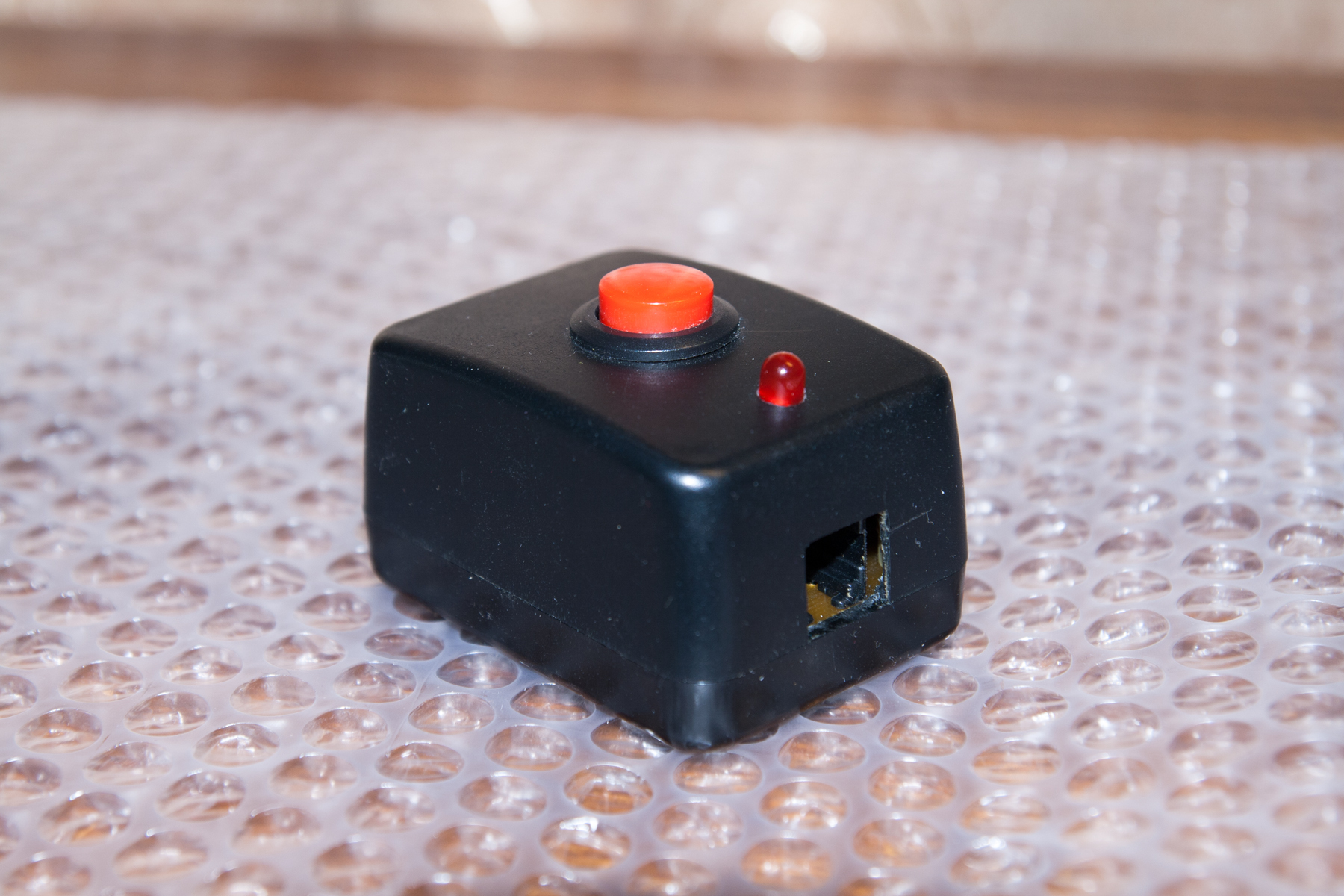
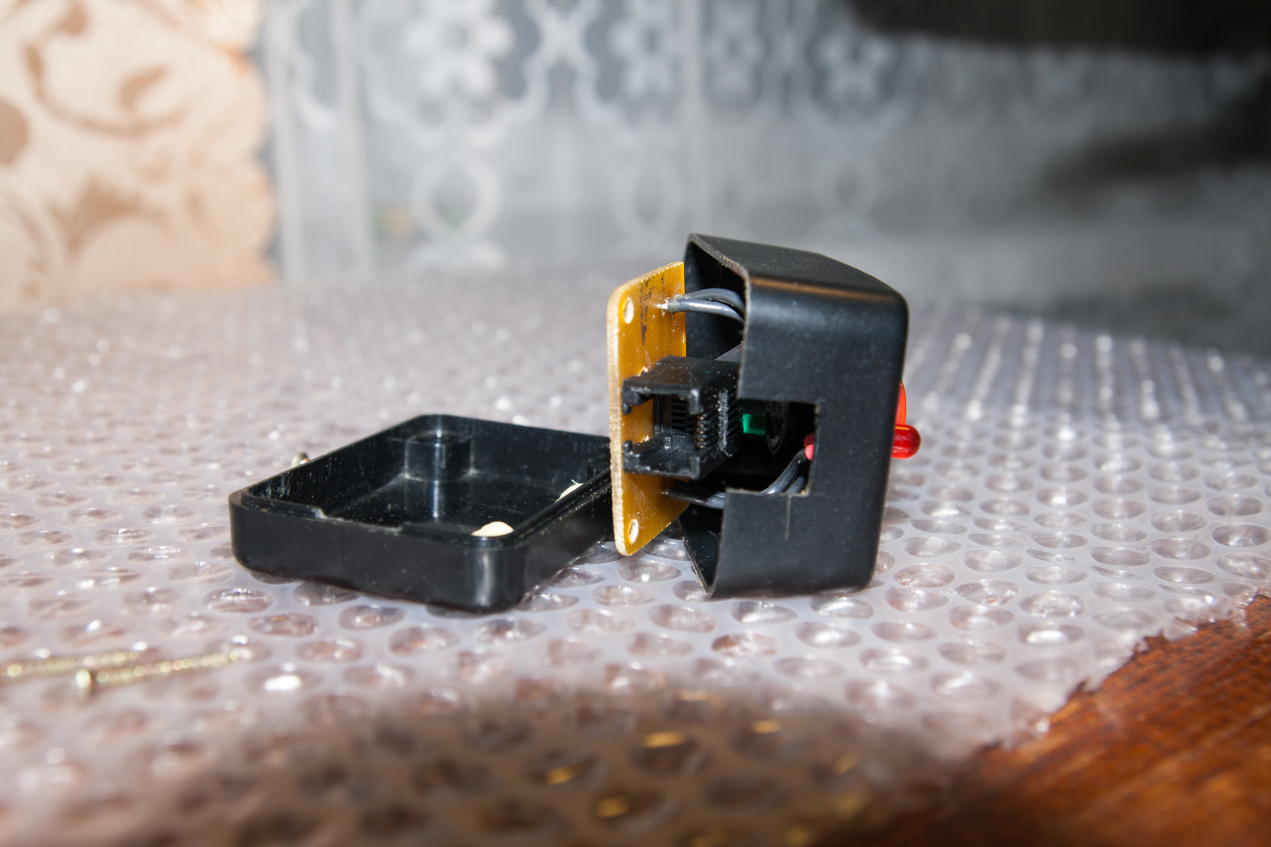
- Convenient remotes with robust buttons and LED display (confirmation to the player that he first pressed the button);
- Detachable connection of consoles and devices. It was decided to make connectors both on consoles and on the system itself. A 4P4C connector (RJ11, commonly used in telephones) was selected. This choice was made because of the small size and ease of cable repair - with the crimping tool and connectors, the problem is solved in a matter of minutes;
- Two possible power sources - external and internal. Looking ahead - it was in the implementation of the power scheme I made the most mistakes;
- The system must have an in-circuit programming connector (ISP) so that the microcontroller firmware can be changed without unnecessary trouble;
- There should be no binding to any other devices (computer, etc.);
- Small dimensions.
As a “brain” of the device, I chose an Atmel – Atmega8 microcontroller, which is extremely popular with hams. Although for the functionality of the system with a head would be enough for some Attiny, it had a fatal flaw - it did not lie in my desk. Unlike the aforementioned Atmega.
Then, I quickly sketched out an approximate concept:

As an external power source was chosen idle power supply from the old modem - at the output, it has 12 V AC voltage. In the role of an internal source, I chose a “Krona” type battery - error No. 1. To generate the 5 V needed for the microcontroller, I set the LM7805 linear stabilizer — error # 2. The fact that these are errors, I learned in practice after assembling and testing the device. It turned out that Krona has a very low capacity, and almost half of it went nowhere - on the heating of the linear stabilizer. However, more on that later.
The buttons and connectors that I chose for the device had to be bought on ebay - too high prices were requested by local merchants. True, I still had to purchase 10-mm LEDs on the radio market - neither on ebay nor on aliexpress, I did not find indicator multi-colored LEDs of the desired diameter.
One of the most important and determining the next steps was the choice of the case. I couldn’t find anything suitable in quality in my city - I had to use trading platforms on the Internet. The variant arranging me was found in Kiev, and 5 buildings were ordered there - for the main unit and for the consoles.
And so, having all the necessary elements on hand, I began to think over the design of the device.
Printed circuit boards
Having a case in my hands, I began to develop printed circuit boards. Here's what I got:
The main circuit board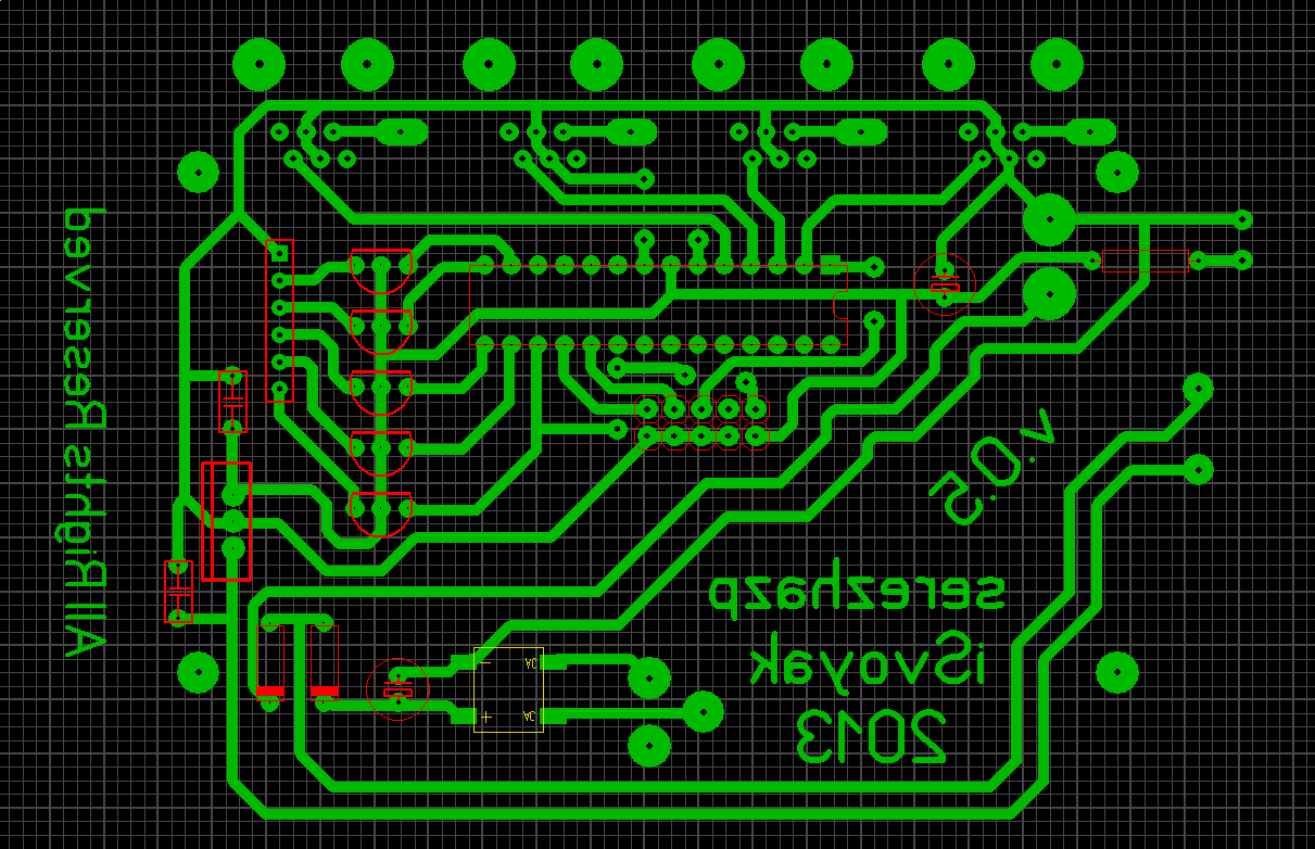
Printed circuit board LED unit
Button circuit board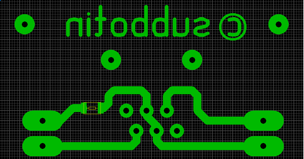
Layouts of printed circuit boards were created in Sprint Layout, at the end there will be links to the sources. Use, modify - in general, do whatever you want with them.
I made the printed circuit boards by the LUT method (laser-iron technology) - in my humble opinion, this is the simplest and most affordable way for a mortal to make a printed circuit board of acceptable quality.
Code
Here, in fact, the listing program of the microcontroller. Perhaps the code is not the most elegant, but it works and performs its function with a bang.
C program code
#define F_CPU 4000000UL #define f 349 #define a 440 #define cH 523 #include <avr/io.h> // /, #include <util/delay.h> // #include <avr/interrupt.h> // // void clear_led(void) { PORTB = 0b00110000; PORTC = 0xFF; } int blink_led(int num) { clear_led(); _delay_ms(100); PORTB |= (1<<num); _delay_ms(100); clear_led(); _delay_ms(100); PORTB |= (1<<num); _delay_ms(100); clear_led(); _delay_ms(100); PORTB |= (1<<num); _delay_ms(100); clear_led(); _delay_ms(100); PORTB |= (1<<num); _delay_ms(100); clear_led(); _delay_ms(100); PORTB |= (1<<num); _delay_ms(100); return 0; } // , - void song(void) { _delay_ms(500); int T = 1000000/440; int k = 500000/T; int i = 0; int tempo = 1; while(i<k) { PORTD = 0b11111111; // : _delay_us(T/2); // PORTD = 0b01111111; // _delay_us(T/2); // . i++; } PORTB |= (1<<0); PORTB |= (1<<1); PORTB |= (1<<2); PORTB |= (1<<3); PORTD = 0b01111111; _delay_ms(500/tempo); // :) T = 1000000/440; k = 500000/T; i = 0; while(i<k) { PORTD = 0b11111111; // : _delay_us(T/2); // PORTD = 0b01111111; // _delay_us(T/2); // . i++; } clear_led(); _delay_ms(500/tempo); // :) T = 1000000/440; k = 500000/T; i = 0; while(i<k) { PORTD = 0b11111111; // : _delay_us(T/2); // PORTD = 0b01111111; // _delay_us(T/2); // . i++; } PORTB |= (1<<0); PORTB |= (1<<1); PORTB |= (1<<2); PORTB |= (1<<3); PORTD = 0b01111111; _delay_ms(500/tempo); // :) T = 1000000/349; k = 350000/T; i = 0; while(i<k) { PORTD = 0b11111111; // : _delay_us(T/2); // PORTD = 0b01111111; // _delay_us(T/2); // . i++; } PORTD = 0b01111111; _delay_ms(350/tempo); // :) T = 1000000/523; k = 150000/T; i = 0; while(i<k) { PORTD = 0b11111111; // : _delay_us(T/2); // PORTD = 0b01111111; // _delay_us(T/2); // . i++; } PORTD = 0b01111111; _delay_ms(150/tempo); // :) T = 1000000/440; k = 500000/T; i = 0; while(i<k) { PORTD = 0b11111111; // : _delay_us(T/2); // PORTD = 0b01111111; // _delay_us(T/2); // . i++; } PORTD = 0b01111111; _delay_ms(500/tempo); // :) T = 1000000/349; k = 350000/T; i = 0; while(i<k) { PORTD = 0b11111111; // : _delay_us(T/2); // PORTD = 0b01111111; // _delay_us(T/2); // . i++; } PORTD = 0b01111111; _delay_ms(350/tempo); // :) T = 1000000/523; k = 150000/T; i = 0; while(i<k) { PORTD = 0b11111111; // : _delay_us(T/2); // PORTD = 0b01111111; // _delay_us(T/2); // . i++; } PORTD = 0b01111111; _delay_ms(150/tempo); // :) T = 1000000/440; k = 1000000/T; i = 0; while(i<k) { PORTD = 0b11111111; // : _delay_us(T/2); // PORTD = 0b01111111; // _delay_us(T/2); // . i++; } PORTB |= (1<<0); PORTB |= (1<<1); PORTB |= (1<<2); PORTB |= (1<<3); PORTD = 0b01111111; _delay_ms(1000); // :) clear_led(); } int beep(int k, int j) // { int i = 0; while(i<k) { PORTD = 0b11111111; // : _delay_us(j); // PORTD = 0b01111111; // _delay_us(j); // . i++; } PORTD = 0b01111111; // :) return 0; } void reset_wait(void) { short t = 0; while(t==0) { if(!(PIND & (1<<PIND4))) { _delay_ms(5); if(!(PIND & (1<<PIND4))) { t = 1; clear_scr(); clear_led(); } } } } int bond007(void) // - { short i = 0; short p = 0; int t = 300; int tone = 100; while(i==0) // { // if(!(PIND & (1<<PIND0)) || !(PIND & (1<<PIND1)) || !(PIND & (1<<PIND2)) || !(PIND & (1<<PIND3)) || !(PIND & (1<<PIND6))) // { // " " _delay_ms(5); // if(!(PIND & (1<<PIND0))) // 1 { // " 1" p = beep(t, tone); // i=1; // clear_led(); p = blink_led(0); reset_wait(); i=0; } // " 1" else { if(!(PIND & (1<<PIND1))) // 2, { p = beep(t, tone); i=1; clear_led(); p = blink_led(1); reset_wait(); i=0; } else { if(!(PIND & (1<<PIND2))) // 3 { p = beep(t, tone); i=1; clear_led(); p = blink_led(2); reset_wait(); i=0; } else { if(!(PIND & (1<<PIND3))) // 4 { p = beep(t, tone); i=1; clear_led(); p = blink_led(3); reset_wait(); i=0; } } } } } // " " } // return i; } int main(void) // { // DDRC = 0xFF; // PORTC = 0xFF; // . DDRD = 0b10000000; // , 8 , , PORTD = 0b01111111; // , 8 , . DDRB = 0xFF; // PORTB = 0b00110000; // 5 6 song(); short i = 0; while(1) // { // i = bond007(); } // return 0; } If suddenly it happens that someone opens the cat and looks at the code, this person will probably have a question - what kind of nonsense is taking most of it. The fact is that I wanted to add some zest to the device, and as this highlight I chose a greeting when I turned it on. Immediately after the first electrons run along the chain, this black box with multi-colored LEDs and the red button begins to play a fun piece from the well-known “Imperial March”.
Here's what it looks like:
In addition to the melody itself, in this short video you can see an example of the system operation: by pressing a button, the corresponding LED on the main device and the indicator light up. In this state, the system is locked until the master presses the red reset button of the system. That is, in fact, the whole logic of the work.
Errors in the project
As I wrote above, the main errors at the design stage concerned the power supply system of the device. The terrible efficiency of the linear stabilizer, which literally transforms the “extra” 4V into heat when powered by the Krona, is the apotheosis of energy inefficiency. And the “Krona” itself is far from the best choice. This battery has a small capacity (about 600 mAh), and it lasts very briefly. With such a power scheme, the system during the first testing in combat conditions worked no more than an hour. It absolutely did not suit me, so I had to redo this part of the scheme.
Shortly before this project, I became acquainted with the lithium-ion batteries of form factor 18650. They proved themselves from the best side. At least, even in cheap Chinese batteries, the capacity in terms of volume unit was significantly higher than that of Krona.
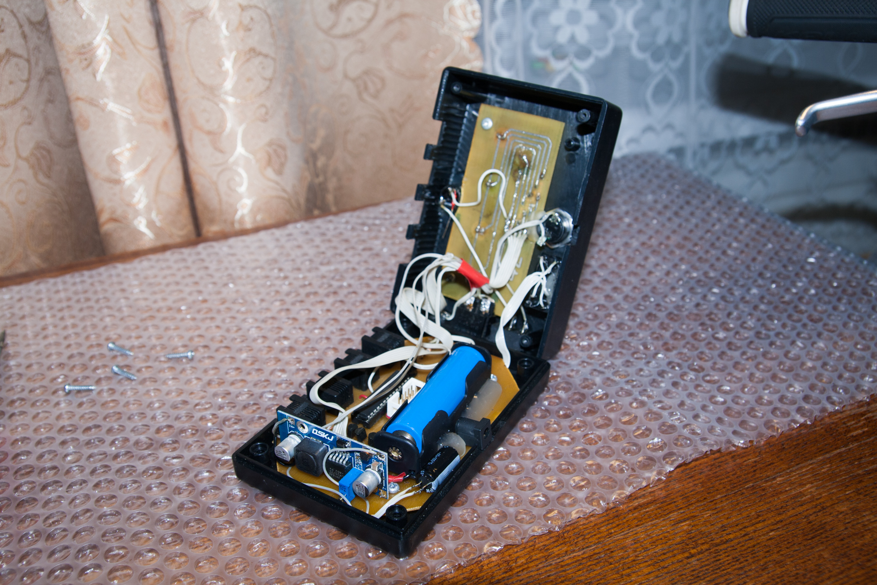
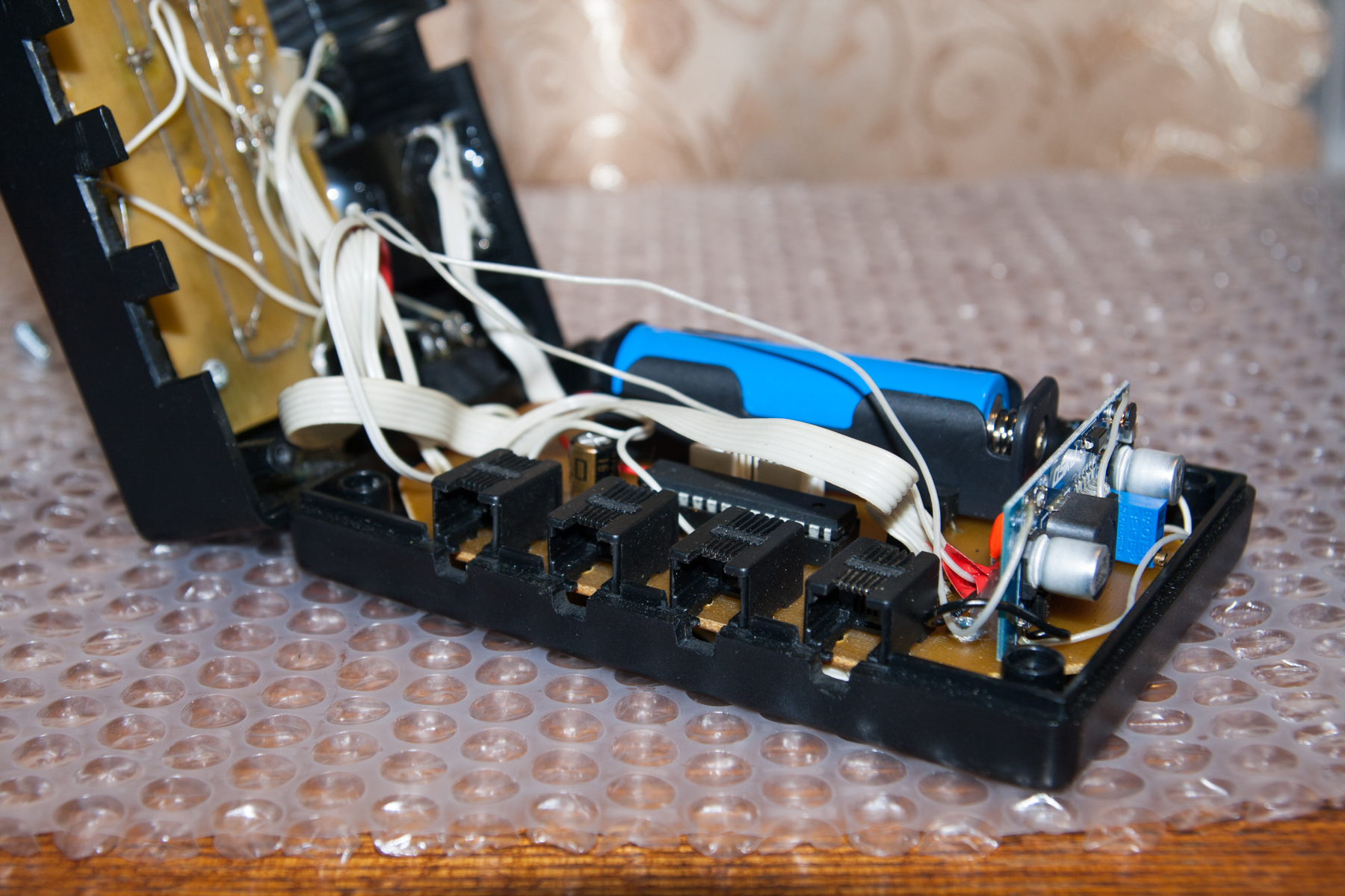
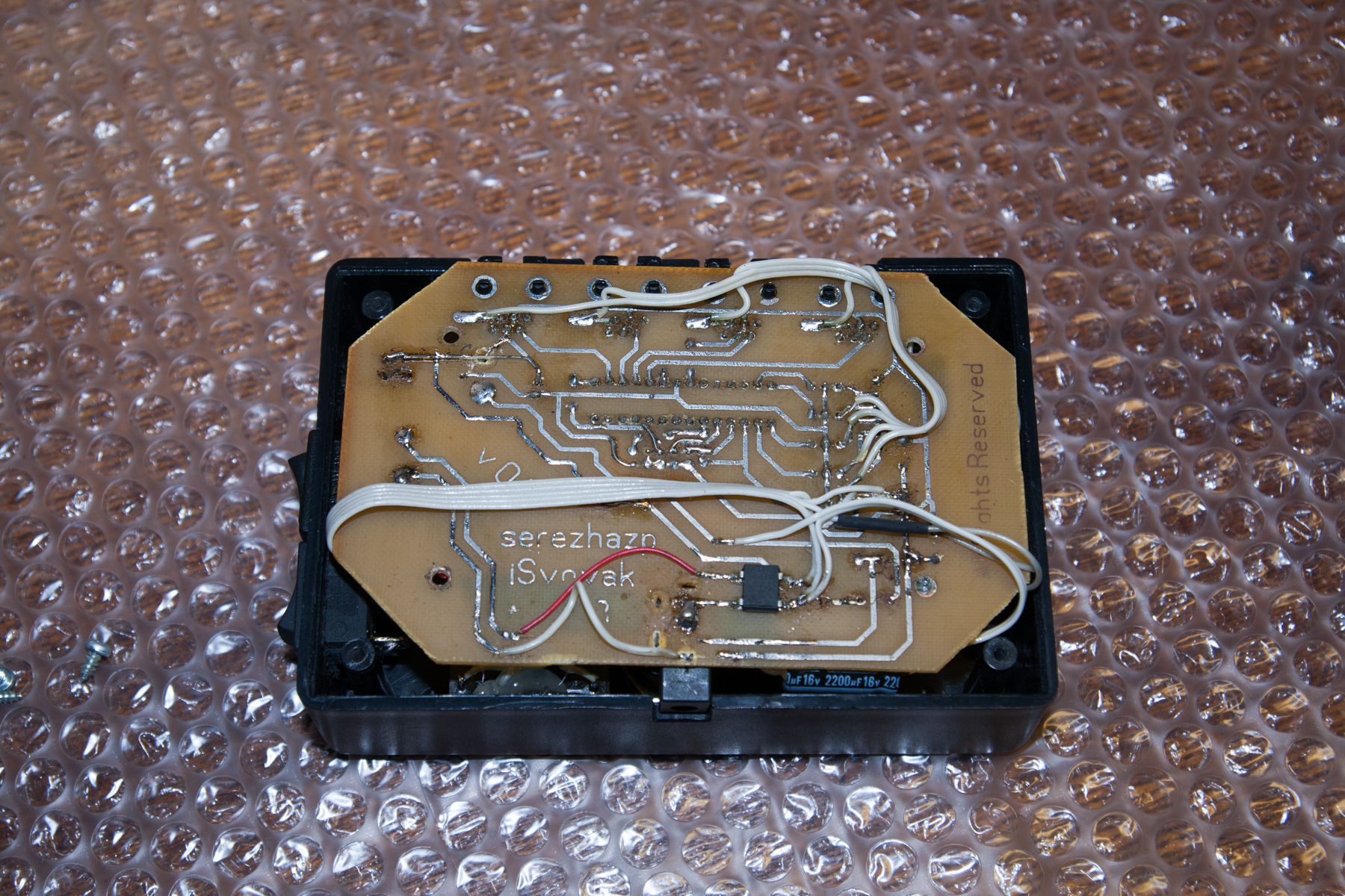
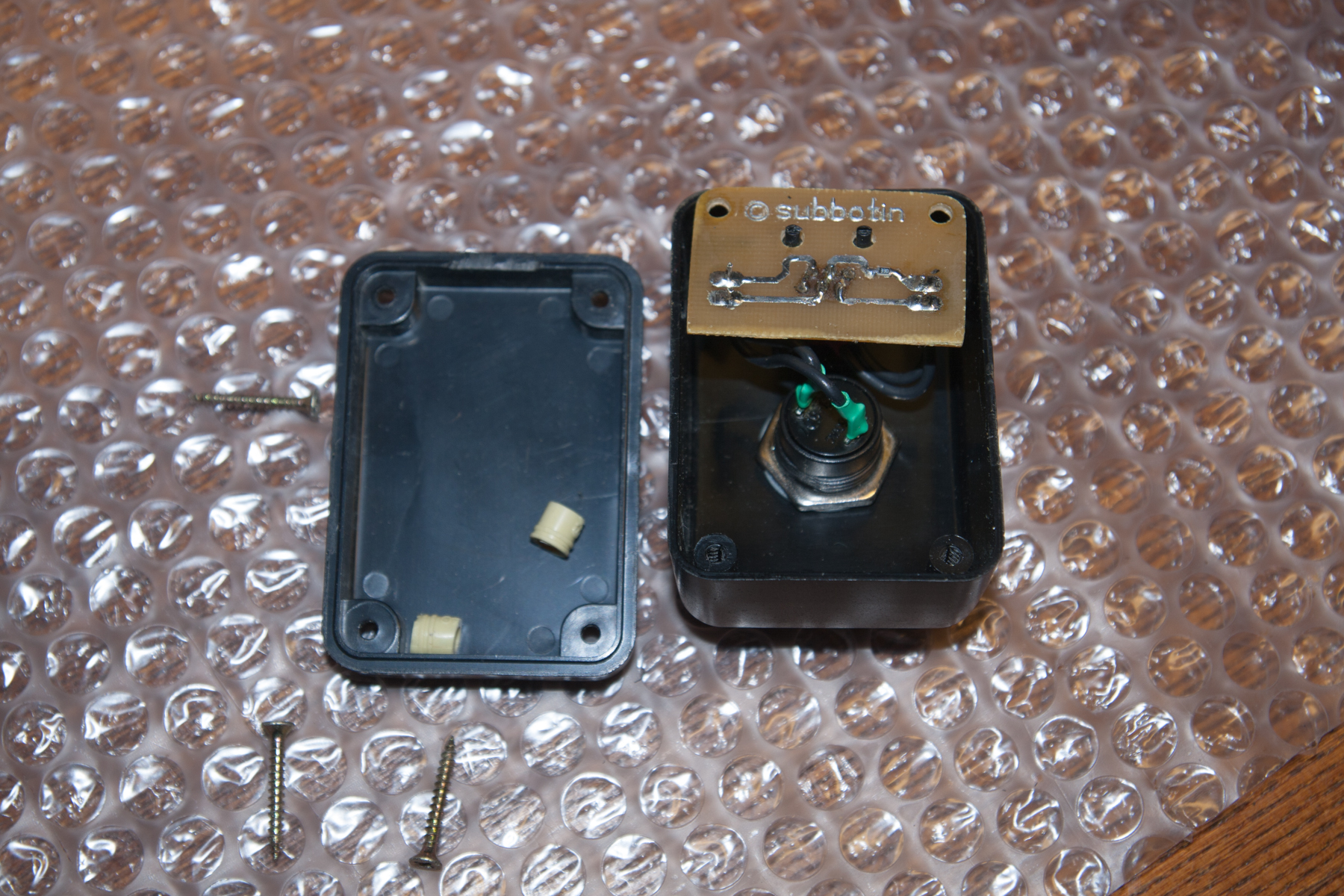
However, with the choice of these batteries, another problem immediately appeared. The rated voltage on such a battery is 3.7 V. And this is not enough to power the Atmega8. The cunning Chinese again came to the rescue - to get the coveted 5 V, I took the boost converter lying idle on the LM2577. Having pulled out the ill-fated LM7805 with the root (the legs remaining in the board can be seen in the photo placed further), I introduced into the power supply system a neat shemka created by hardworking residents of the PRC.
In addition, at the time of testing this version of the scheme, I decided to abandon the possibility of connecting an external power source. The field tests went off with a bang - after many hours of operation there were no signs of battery discharge or voltage drop (“Krona” gave drawdown - apparently, it could not give the current required by the circuit). I decided to continue the tests until my glorious noname 18650 refuses to run the circuit.
By the way, in the description of the lot, when buying, a capacity of about 3,700 mAh was declared - very self-confident even for the Chinese, considering the cost of one can of about $ 3. But it turned out that in a few months of work (which also speaks of the low self-discharge of batteries), the battery never sat down. Because I gave up earlier and charged the battery for trouble-free operation of the device at one important event, which will be mentioned later.
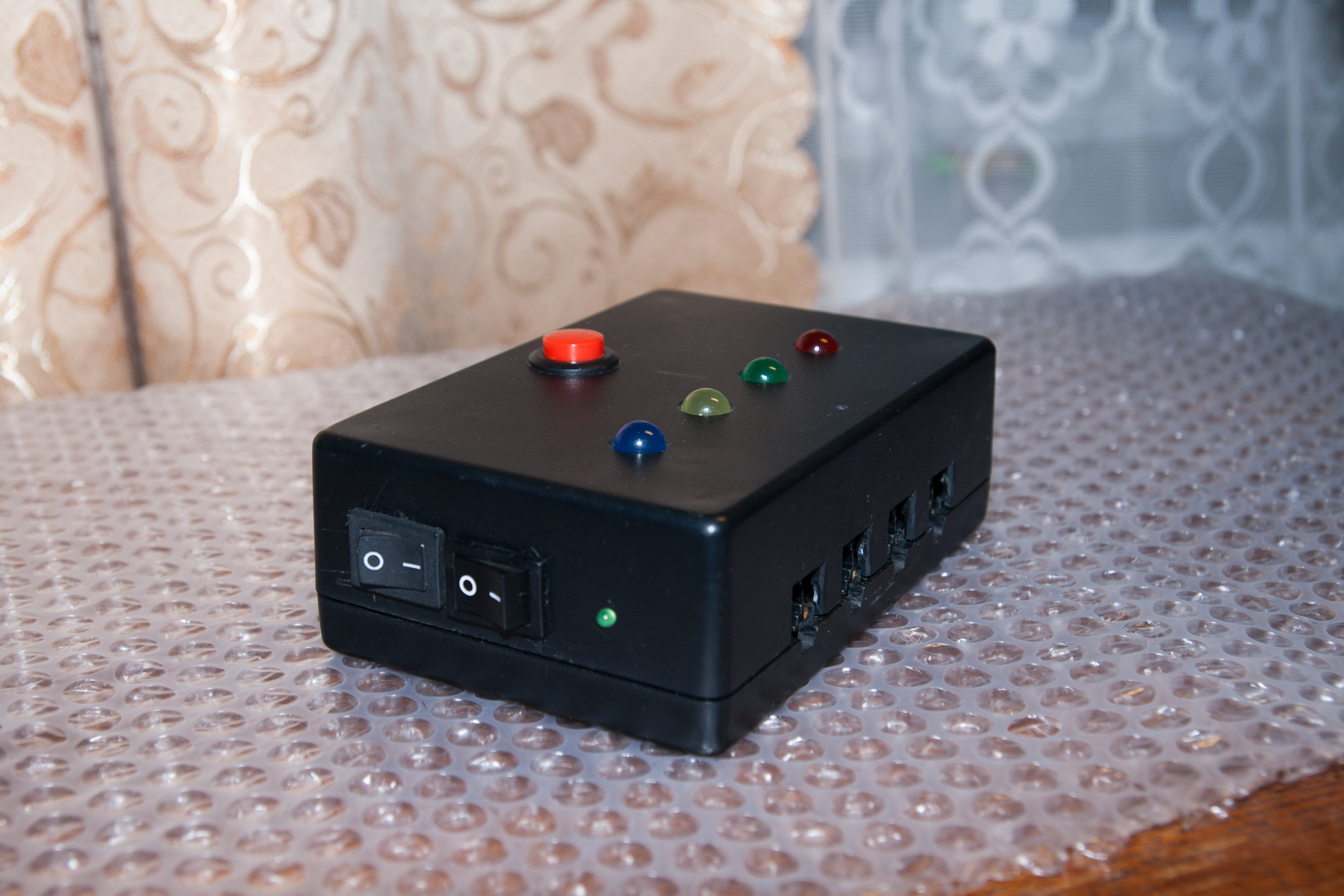
Photo
Here I bring a photo of the resulting apparatus, including the inside view. This is to make it clear that everything is done honestly - there is no neon inside.
Total
The system turned out to be workable, performing its function by 100%. In addition to training, it was tested at CHUSI-2013 (Ukrainian Championship in "His game" of 2013), in which your humble servant was one of the leaders.
It was a wonderful experience, which, as you know, is the son of difficult mistakes. In the final implementation, the device lost some of the functions that were originally intended. For example, I refused to connect an external power supply - even with active use of the system, a mediocre battery lasts for many months.
Below I enclose links where you can download printed circuit boards (in .lay format) and ready firmware for the microcontroller. I would be glad if someone will benefit from my work.
Main circuit board ;
Printed circuit board LED unit ;
Printed circuit board buttons ;
Firmware
Source: https://habr.com/ru/post/241407/
All Articles