Another little engineering investigation or cry Yaroslavna
“I knew it would be bad, but I didn’t know that so soon” (V. Tsoy)
I don’t know what caused the writing of this post, it’s probably just painful, but the specific motive was two events - one FROM abroad, and the other of domestic origin. It is not known what is worse, but judge the reader about this, so let's begin.
It all started with the fact that one of the products of our company did not turn on at a low temperature. Since the Murata power supply module used in this product has already been used in other products and did not create any problems, it was our board that was pestered for a long time. However, after all possible explanations were rejected (as a result of checks and experiments), the last remaining option is correct, no matter how unlikely it seems (Sherlock Holmes method).
That is, it was suggested that the case is really in a standard module from a well-known company. And indeed, experiments have shown that the power supply module at certain values of the input voltage (inside the working area) and certain values of the module temperature (also inside the allowable ones) cannot be switched on when working for a capacitive load exceeding a certain value (and almost extending to the maximum allowable).
It turned out that this was not characteristic of a specific module, but of the entire batch, at least 10 modules that we tested, gave the same picture. Moreover, in the process of the tests described above, that is, being deep inside the permissible operating conditions, 3 modules failed irrevocably. Of course, it would be extremely interesting to investigate modules from the old lots in such modes, but by that time they were no longer available because they were in long-shipped products, so it was assumed that changes in behavior are associated with any changes in the production of these modules.
')
Our actions were quite unambiguous - we informed the dealer and waited for the arrival of his representative to conduct joint research. But while we waited, we decided to try to sort it all out ourselves. Simplified scheme to the limit. So, we connect an electrolytic capacitor of 2 * 680 microfarads in parallel with the 56Ohm resistor to the output of the power supply module under study and watch the oscilloscope form the voltage across it.
We observe the following funny picture (again, some neponyatki with flowers, but oh well):
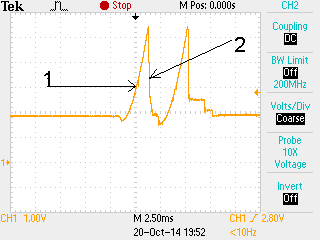 "
"So after powering the module begins to output the required voltage. But if he tries to apply a voltage surge to the output, then this would require an infinitely large instantaneous current, since we have a capacitor at the output, the voltage on which cannot increase abruptly. In the real world, of course, not an infinitely large but very significant current is required.
Since the module is designed for a very specific value of the output current, it implements protection against exceeding the output current (usually 110-120% of the maximum), it will work at the moment of issuing this significant current and turn off the source. In order to prevent this from happening, the module is equipped with a soft start circuit, which at the initial moment limits the value of the output current at a level significantly less than the worker (and, accordingly, maximum), and then within a certain time this current starts to increase smoothly, which is good for the graph shows, the growing front is clearly accelerating.
When the current reaches the maximum allowable value, the protection circuit will work and the module will turn off. The rise time was 2.5 msec, which is not enough, but acceptable. However, according to the oscillogram, it turns out that this current was only 5A, which again is not enough for a module with an output voltage of 5V and a power of 50W, but this is the second question. At least with the front of the output dress everything is clear.
This behavior of power sources is typical when working on a high capacitive load, while we observe characteristic steps - the capacitor charged to a certain value, the module turned off, paused, tried to turn on again, the voltage on the capacitor did not fall to zero, therefore the initial current is significantly less than the first time and the protection is triggered later, the capacitor is still recharged and in 2-3-4 such cycles the voltage reached the nominal and only the leakage current goes through the capacitor, practically does not affect yay to work module. That is how the power modules of the domestic manufacturer behaved in this scheme, which was later, and everything was fine.
But on the oscillogram we see a slightly different picture - the capacitor is charging, the protection is triggered, the module is turned off, but then the voltage on the capacitor decreases sharply, and the discharge current exceeds the charge current by an order of magnitude - almost vertical drop. In this case, the voltage decreases to 0, the new charge cycle repeats the first one, and we never enter operating mode.
Unfortunately, the company does not provide schemes for its modules, and we are forced to enter upon unsteady ground of conjectures and assumptions. What could be the cause of this behavior? The answer that seems logical to me is the following. Currently, in the output stages of transformer power sources, it is customary to use transistors (usually field-type), instead of rectifier diodes, the so-called synchronous rectifier circuit. This solution allows you to significantly reduce losses on the rectifier element, instead of 1-1.3 volts direct drop on the diode, which at a current of about 10 amperes will give 10-13W, we have 100-150mV, which reduces the power output by an order of magnitude.
But the transistor, unlike the diode, must be controlled and there are various methods for this, historically the first of these was direct control. If we have a push-pull circuit, the transistor control from the opposite winding is widely used. This scheme has its advantages (simplicity), but it has greater switching losses than the scheme with direct control. Modern microcircuits for building power sources, as a rule, have additional outputs for implementing this transistor control mode, so it has become very popular, we can assume that it is implemented in our case.
But a field-effect transistor differs from a diode not only in that it has a lower voltage drop, but also in the fact that it is capable of conducting current in both directions. This aspect is usually not paid due attention, but in field-effect transistors the drain and source are indistinguishable from the point of view of operation (the statement is strong, but true for a certain class of devices). Therefore, if we turn off the pump transistors, but do not take measures to forcibly turn off the output transistors (like diodes), then the output voltage closes to ground through these transistors along the drain-source circuit and, accordingly, the output capacitor is very quickly discharged, which we and watch.
Further actions to test this hypothesis are obvious: we turn on the diode between the output of the module and the capacitor (again a field-effect transistor in diode mode, but with direct control) and everything turned out - the voltage reaches the operating level in 3 cycles. Nevertheless, we are not thrilled, because we had to refine the scheme, and, as they say, on level ground.
A dealer representative comes to us, we will show him a working scheme, a test stand, oscillograms with and without a diode and offer our version of what is happening. He begins to doubt, offers to turn on a resistor of about 10 ohms instead of a diode and this also helps. Well, it would not have helped - we have reduced the discharge current of the capacitor, as is the case with a diode. Nevertheless, it seems that we did not convince him, but nevertheless we record the fact that the modules do not work in certain modes when using the scheme recommended by the company. The proposal to put a series resistor and allocate 1W of power on it to compensate for the shoals, does not seem to me successful.
Well, now I turn to the promised Yaroslavna crying in the title. The representative leaves with the signed acts and what? After a while, a message arrives that they are ready to replace us with 3 failed modules at their own expense and ALL. No changes in the recommended connection scheme, no changes in the circuitry, no newsletter on the manufacturer’s website for other users - nothing. And this is not Pupkin and Co., a global manufacturer with a well-known brand, who does not seem to care at all about the defect found in their standard products (at least in a specific batch of products), making it impossible to use it in certain conditions. What happens to the electronics industry? Have the caders finally won? And on a global scale? Here is such a cry from the middle-aged developer.
Well, the second part of the story is not so terrible, it just coincided with the first, which is why it got here. After such a case, the credibility of the company's products decreased and they began to look for options. Since we already actively used the power modules of one domestic company (since I am going to scold it, the name will be encrypted - it produces standard power modules with acceptance 5 and this is not IRBIS - smart enough), and there were no quality complaints about them, we decided to look , whether they have something suitable.
The fact is that their source series are quite good (and indeed, the work with this company left a good impression - normal documentation, imputed technical support, if you know who to call), but these sources have significantly larger dimensions, since the power density is 2- 3 times less. And here on the site there is a new series of sources that have a power density even slightly higher than that of MURATA (of course less than that of VICOR, but this is a separate song, very few people compete with them, and they have enough of their cockroaches) 5, moreover, we will conduct import substitution (I don’t know how it is from anyone, but this is a sore point for us).
The layout of the legs, however, is somewhat different, but still standard. I am happy, I inform the management about such glorious guys and their products, we rejoice together for the country in which there are still such cool developers, we begin to figure out the options for use. And then I call this unnamed company in order to acquire samples and drive them in the whole range and it turns out that these products are not being manufactured yet, even engineering samples with GK acceptance are not available, acceptance 5 will, of course, sometime later, and orders for they will start to collect the commercial version NOT EARLIER than the second half of 2015. So I had the first question - guys, why cheat? After all, who needs it, he will find out the truth - he will call you. Honestly write that this is a promising development, but on your site it is said that the modules are being released (after a lively discussion of this issue with them, this is now indicated on the site - in development). And the second question - is it really possible to launch even a new series, but still, power sources with unsaturated parameters take more than six months? If I am told “no earlier than the second half” of the year, I hear “at the end”, I will be glad to be mistaken. But this is so, grumbling, but in general the guys are great, and if they withstand the stated parameters, they will bite their share of the market from foreign firms, especially in connection with recent events.
I apologize in advance if I offended anyone, I somehow wrote a mess, but I won't erase anyway.
Source: https://habr.com/ru/post/240897/
All Articles