Accident Alert Info Panel Project (Part 3)
Greetings to all.
This is the third part of a rather long history ( one , two ).
The device is not yet complete, although almost all the main blocks are currently assembled:
- Indicators (2);
- Processor module (in this part);
- Power supply (pulse converter 48V -> 5V to 6A) (in the process, pause due to the finally breaking probes to the oscilloscope (keTai));
Action plan:
[+] SD-Card-Sector
[+] FAT-FS
[+>] OneWire async
[-] Slave firmware
[part] Ethernet
[-] Interprocessor exchange protocol
[-] Bootloader
Carefully photo.
')
Processor board has changed:
In the first variant, it was not possible to dilute the PORTA of the main controller, in variant 2 it was corrected - brought to the full comb. It is possible to use both additional periphery and as a DAC (if you can get the audio playback from UDP packets to work without failures).
Modular periphery. Provided on the board:
- DS18B20 temperature sensor (or any other OneWire devices);
- Clock DS1307;
- Hardware console (TTL levels, 115200, N, 1);
- Piezo emitter (squeaker, connector);
- Status module (plug);
Type of module: It would be very good to make mini-windows for it so that the diodes do not light up the "neighbors".
The screen control processor has got an additional connector for connecting external indicators (a clock, just a clock) without additional power - they will take it directly from the power supply unit.
The code is not yet compiled. I am engaged in the hardware (at the moment - indicators:
Dynamic indication, transistor row and column drivers, a duty cycle of 8 for each row. Schemes and models of boards will be later.
FAT: Partial database - use the library from “ www.roland-riegel.de ” (the library page ). I want to write myself, so the files, although distributed under the GPL license, are used as an example.
Miraculously earned the function of reading / writing from / to the SD card / y. Initialization proceeds normally, the map is determined, but zeroes are returned when reading. There was a strange crutch when requesting a read / write sector - you need to add a constant to the absolute address. For ordinary maps, the formula is: Calculated_Address = (Required_Sector + 249) * 512. For SDHC, you have to add 2048.
Tested cards:
Transcend MicroSD 1GB / Taiwan / (I C1210000 924)
Transcend MicroSD 2GB / Taiwan / (8281AB 2G 01DS1)
Samsung MicroSDHC 8GB Class 2 / Taiwan / (C FJCB85PZ T15)
Kingston MicroSCHC 16GB Class 10 / Taiwan / (TM2I121100200)
The observed strange behavior of the cards is reproduced.
Question to readers: Has anyone encountered a similar experience with AVR * with SD cards?
There is a difficulty with the Ethernet module - the module itself works, but you cannot connect it to the network with the presence of active PoE power. A direct link to the datasheet of transformers used in Arduino-compatible Ethernet modules - all 4 pairs of them have a midpoint pulled up to a common point inside the circuit with 75 Ohm resistors (it’s logical that these are linear terminators). With such a connection, only two options are possible - either the power supply goes into protection or the socket burns out. Both are unpleasant.
Now I am making an Ethernet board (in fact, I am reworking the Arduino-ENC28J60 module I purchased to a new board). The module turned out to be 71 * 33mm (for comparison, the module from the Arduino is 55 * 35mm).
Boards do without metallization of the holes, jumpers on the next layer.
Recently, the asynchronous library for OneWire has been more or less debugged. It is not yet fully written, there are no interfaces and other things, it reads the previously designated number of bytes. It is necessary to alter a few objects to simplify working with it.
This is the third part of a rather long history ( one , two ).
The device is not yet complete, although almost all the main blocks are currently assembled:
- Indicators (2);
- Processor module (in this part);
- Power supply (pulse converter 48V -> 5V to 6A) (in the process, pause due to the finally breaking probes to the oscilloscope (keTai));
Action plan:
[+] SD-Card-Sector
[+] FAT-FS
[+>] OneWire async
[-] Slave firmware
[part] Ethernet
[-] Interprocessor exchange protocol
[-] Bootloader
Carefully photo.
')
Processor board has changed:
Hidden text
V.1:

Disassembled, moved to the next.
V.2:

Disassembled, moved to the next.
V.2:
In the first variant, it was not possible to dilute the PORTA of the main controller, in variant 2 it was corrected - brought to the full comb. It is possible to use both additional periphery and as a DAC (if you can get the audio playback from UDP packets to work without failures).
Modular periphery. Provided on the board:
- DS18B20 temperature sensor (or any other OneWire devices);
- Clock DS1307;
- Hardware console (TTL levels, 115200, N, 1);
- Piezo emitter (squeaker, connector);
- Status module (plug);
Type of module: It would be very good to make mini-windows for it so that the diodes do not light up the "neighbors".
Hidden text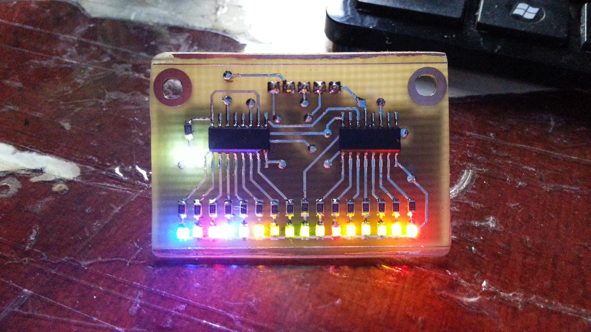
The screen control processor has got an additional connector for connecting external indicators (a clock, just a clock) without additional power - they will take it directly from the power supply unit.
The code is not yet compiled. I am engaged in the hardware (at the moment - indicators:
Hidden text
Dynamic indication, transistor row and column drivers, a duty cycle of 8 for each row. Schemes and models of boards will be later.
FAT: Partial database - use the library from “ www.roland-riegel.de ” (the library page ). I want to write myself, so the files, although distributed under the GPL license, are used as an example.
Miraculously earned the function of reading / writing from / to the SD card / y. Initialization proceeds normally, the map is determined, but zeroes are returned when reading. There was a strange crutch when requesting a read / write sector - you need to add a constant to the absolute address. For ordinary maps, the formula is: Calculated_Address = (Required_Sector + 249) * 512. For SDHC, you have to add 2048.
Hidden text
uint8_t SPI_SD_READ_SECTOR(uint32_t Sector) { uint16_t i; uint32_t calc_Addr; if (Sector == raw_block_buffered) // { return R_OK; // . , . }; SPI_Select_CARD(); if (!(sd_raw_card_type & (1 << SD_RAW_SPEC_SDHC))) // SDHC - 9 . { // !SDHC calc_Addr = ((Sector+249) << 9); // DaFaq?! But will not work in other case. } else { // SDHC calc_Addr = (Sector+2048); // And one more DAFAQ! }; i = SPI_SD_SendCMD(CMD_READ_SINGLE_BLOCK, calc_Addr); // if(i) { SPI_UnSelect_CARD(); // return R_ERR; // . =( }; while (SPI_SD_Rd_Byte() != 0xFE); // . 30-40 . for (i=0; i<512; i++) // (512 ) { raw_block[i] = SPI_SD_Rd_Byte(); }; SPI_SD_Rd_Byte(); // CRC SPI_SD_Rd_Byte(); // CRC (2) // IGNORED T_T /* deaddress card */ SPI_UnSelect_CARD(); // () SPI_SD_Rd_Byte(); // . raw_block_buffered = Sector; // , . return R_OK; }; Tested cards:
Transcend MicroSD 1GB / Taiwan / (I C1210000 924)
Transcend MicroSD 2GB / Taiwan / (8281AB 2G 01DS1)
Samsung MicroSDHC 8GB Class 2 / Taiwan / (C FJCB85PZ T15)
Kingston MicroSCHC 16GB Class 10 / Taiwan / (TM2I121100200)
The observed strange behavior of the cards is reproduced.
Question to readers: Has anyone encountered a similar experience with AVR * with SD cards?
There is a difficulty with the Ethernet module - the module itself works, but you cannot connect it to the network with the presence of active PoE power. A direct link to the datasheet of transformers used in Arduino-compatible Ethernet modules - all 4 pairs of them have a midpoint pulled up to a common point inside the circuit with 75 Ohm resistors (it’s logical that these are linear terminators). With such a connection, only two options are possible - either the power supply goes into protection or the socket burns out. Both are unpleasant.
Now I am making an Ethernet board (in fact, I am reworking the Arduino-ENC28J60 module I purchased to a new board). The module turned out to be 71 * 33mm (for comparison, the module from the Arduino is 55 * 35mm).
Hidden text
Typical scheme from the description to the module.

The divorced board (the transformer from some device found in the office basket, the M-TEK G24102MKG, is very badly googled).

Fee assembly. The transformer was broken. But, since in the discarded donor device, only the first pairs were used, he earned in ... this form.

The divorced board (the transformer from some device found in the office basket, the M-TEK G24102MKG, is very badly googled).
Fee assembly. The transformer was broken. But, since in the discarded donor device, only the first pairs were used, he earned in ... this form.
Boards do without metallization of the holes, jumpers on the next layer.
Recently, the asynchronous library for OneWire has been more or less debugged. It is not yet fully written, there are no interfaces and other things, it reads the previously designated number of bytes. It is necessary to alter a few objects to simplify working with it.
Source: https://habr.com/ru/post/240827/
All Articles