The minimum Hello Word limit on the AVR is 2 bytes.
For this week, two articles appeared at once in Habré and one in the blog, where the authors competed in writing the minimum possible LED blinking program for AVR microcontrollers.
In the most recent article, the author proposed a program of only 4 bytes (!)
Well, how can you resist the challenge?
And in this article, I propose a flashing LED program with a frequency that is visible to the eye and is only 2 bytes in size.
2 bytes is the minimum possible length of a program, since the size of an addressable cell of program memory in AVR microcontrollers is 16 bits or 2 bytes. Thus, a program, or rather one instruction (which can be located at absolutely any address) will occupy one cell of program memory.
But, unfortunately, the program proposed by me will not work in all AVR microcontrollers, but only in some models from the Tiny and Mega families.
The secret of the program is that some microcontrollers of the Tiny and Mega families have a remarkable feature that allows you to invert the state of the digits of the PORTA, PORTB and PORTD registers with just one command. This interesting feature is implemented by the sbi A, b command .
')
The sbi A, b command is used to set the I / O register bit, which has addresses from 0 to 31.
This binary command looks like this:
1001 1010 AAAA Abbb
The first eight bits 1001 1010 are the operation code - this is the constant component of the command.
In AAAAA bits, the address of the I / O register is recorded in the I / O address space. For the address, 5 bits are allocated and for this reason, the command has an address restriction (0..31).
In the lower three bits, bbb is the number of the bit being changed (0..7).
Now let's return to the most remarkable feature that allows you to invert the state of the bits of the PORTB and PORTD registers.
Let's take a look at the datasheet on the ATtiny2313 microcontroller:
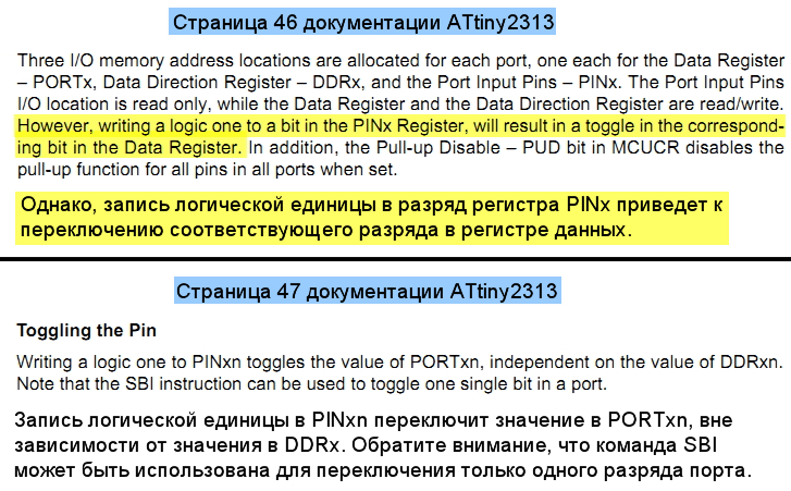
This feature is precisely present in the microcontrollers ATtiny2313, ATtiny13, ATtiny24 / 44/84 .
In the mega microcontrollers of the mega family, such a convenient function is in the ATmega48A / PA / 88A / PA / 168A / PA / 328 / P. But in ATmega8A / 16A / 32A this feature is missing.
And I can’t say with certainty about the other microcontrollers.
In order to find out whether such a function is present in the microcontroller, you can search in the datapix phrase Toggling the Pin .
Thus, by writing, for example, the command sbi PINB, 0, you can invert the state of the zero position of the PORTB register.
And what will it give us?
And this gives us the on / off pull-up resistor in the zero-bit port of port B (do not forget that after reset all I / O registers are reset, therefore ports B and D are configured for input). The resistance of the built-in resistor is 30..50 kΩ. However, even such resistance is quite enough to turn on low-consuming blue, red and white LEDs. But on the green LEDs current will already be missed.
Personally, I use this method of powering LEDs quite often. The red and blue LEDs of standard size 0805 and 0603 are lit quite tolerably at a supply voltage of 5 V.
That is, in order to light the LED, it must be turned on between the port terminal and the common wire (without an external current-limiting resistor!) And turn on the internal pull-up resistor. In this circuit, the external current limiting resistor is also saved.
So, we managed to control the LED using one command.
Now, if this command is written into the program memory of the microcontroller, for example, at the address 0x0000, the microcontroller will work as follows:
At the zero address, the sbi PINB, 0 command will be met and after its execution, the PORTB zero point will be set to one, the pull-up resistor will turn on and the LED will light up. And then, until the end of the program memory, the microcontroller will encounter only 0xFFFF. Such instructions to the microcontroller are unknown, so the microcontroller will simply skip them, spending every one clock cycle and increasing the software counter by one.
After the program counter reaches the end of memory, it will overflow and reset to zero, that is, it will go to the address 0x0000, where the sbi PINB, 0 command will be executed again. After executing the zero-bit command, PORTB will reset to zero, the pull-up resistor will turn off and the LED will go out.
Now let's calculate the frequency with which the LED will flash. As a microcontroller, select, for example, ATtiny2313. In this microcontroller, the program memory is 2048 bytes. Each cell of the program memory is 2 bytes. The address space of program memory is represented by addresses from 0 to 1023. That is, a total of 1024 addresses. After powering the microcontroller will start the program from the address 0x0000. When the microcontroller reaches the address 1023, the program counter will be reset to the next clock cycle. That is, there will be a transition to the address 0x0000.
All commands in our program are executed in one measure. Therefore, the LED will switch to the opposite state once per 1024 cycles. Suppose the microcontroller operates at 1 MHz. At this frequency, one clock cycle is 1 µs. Thus, the switching of the LED will occur every 1024 μs. As you know, frequency is the reciprocal of a period. And the period of one blink is twice the time between switching the LED 1024 μs * 2 = 2048 μs. From where we get the flashing frequency of the LED 1 / (2048 μs) = 488 Hz.
Too much happened. The human eye at such a flashing frequency will not notice. In order for the flashing frequency to be noticeable to the eye, it will be necessary to lower the frequency. To do this, you can start a microcontroller from the clock watchdog timer generator, whose frequency is about 128 kHz. But in reality, the frequency may differ by 3..4 kHz, since the timer is not intended for accurate time counts.
128 kHz is 8 times lower than 1 MHz. Therefore, the flashing frequency will be 8 times lower than 488 Hz / 8 = 61 Hz. Same a lot. Blink to the eye will not noticeable.
To further reduce the frequency, you should enable the fuse-bit CKDIV8, which is responsible for dividing the frequency by 8. Then the clock frequency will be 128 kHz / 8 = 16 kHz, and the flashing frequency will decrease by another 8 times and will be 61 Hz / 8 = 7.6 Hz . But this frequency will already be quite noticeable by eye.
But be very careful when lowering the frequency to such values!
Remember the important rule: if you program a microcontroller with a serial in-circuit programmer (programming via SPI), then the microcontroller's clock frequency must be at least 4 times higher than the programming frequency.
That is, when the clock frequency of the microcontroller is 128 kHz, the frequency of the programmer (SPI frequency) should be lower
128 kHz / 4 = 32 kHz.
And with a clock frequency of 16 kHz, the programming frequency should be lower
16 kHz / 4 = 4 kHz.
Before lowering the clock frequency to 16 kHz, make sure that your serial programmer is able to program at a frequency below 4 kHz.
Otherwise, you risk “blocking” the microcontroller!
This restriction does not apply to parallel programmers.
Now let's finally write our program.
We will write the program in a notebook and immediately in machine codes.
We already know what the sbi A, b command looks like.
1001 1010 AAAA Abbb
It remains to substitute the necessary bits.
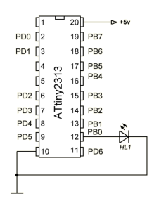
Let's light up the LED that is connected to the zero-bit of port B. In the ATtiny2313 microcontroller, the address is PINB = 0x16. In binary form, 0x16 = 0b10110.
We will change the zero bit, so bbb = 000.
Substitute the bits and get: 1001 1010 1011 0000 or 0x9AB0
Now create a HEX file for the microcontroller firmware.
The composition of the HEX file is as follows:

Our HEX file will consist of two lines: the first line will contain a two-byte instruction 0x9AB0, and the second line will indicate the end of the HEX file.
As the address where our team will be located, we will choose the zero address. Although, you can choose absolutely any address from the entire address space.
The checksum is calculated by subtracting all bytes from the string from zero. The low byte of the resulting value is just the checksum.
That is, for our case, 0x00 - 0x02 - 0xB0 - 0x9A. The low byte is 0xB4. We enter it at the end of the line.
The last line should indicate the end of the HEX file and should look like this:
: 00000001FF
And you also need to remember that in the HEX-file the command bytes are swapped. That is, we first write the low byte 0xB0, then the high byte 0x9A.
The final HEX file will be like this:
: 02000000B09AB4
: 00000001FF
We write the resulting lines into a notebook and save with the extension .hex (however, you can save with any extension).
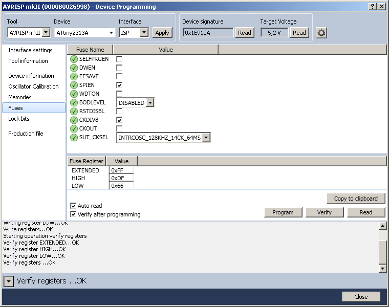
Now it remains to sew this firmware into the microcontroller, set the clock from the watchdog generator, and enable division by 8.
Here is an example of setting fuse-bit in the Atmel Studio 6 environment.
We get the result in the form of a flashing LED. Tested in the gland. Flashing regularly.
Thus, the simplest program consists of two bytes, and the simplest scheme consists of a battery, a microcontroller, and an LED.
Anyone write an LED blinking program even shorter?
In the most recent article, the author proposed a program of only 4 bytes (!)
Well, how can you resist the challenge?
And in this article, I propose a flashing LED program with a frequency that is visible to the eye and is only 2 bytes in size.
2 bytes is the minimum possible length of a program, since the size of an addressable cell of program memory in AVR microcontrollers is 16 bits or 2 bytes. Thus, a program, or rather one instruction (which can be located at absolutely any address) will occupy one cell of program memory.
But, unfortunately, the program proposed by me will not work in all AVR microcontrollers, but only in some models from the Tiny and Mega families.
The secret of the program is that some microcontrollers of the Tiny and Mega families have a remarkable feature that allows you to invert the state of the digits of the PORTA, PORTB and PORTD registers with just one command. This interesting feature is implemented by the sbi A, b command .
')
The sbi A, b command is used to set the I / O register bit, which has addresses from 0 to 31.
This binary command looks like this:
1001 1010 AAAA Abbb
The first eight bits 1001 1010 are the operation code - this is the constant component of the command.
In AAAAA bits, the address of the I / O register is recorded in the I / O address space. For the address, 5 bits are allocated and for this reason, the command has an address restriction (0..31).
In the lower three bits, bbb is the number of the bit being changed (0..7).
Now let's return to the most remarkable feature that allows you to invert the state of the bits of the PORTB and PORTD registers.
Let's take a look at the datasheet on the ATtiny2313 microcontroller:
This feature is precisely present in the microcontrollers ATtiny2313, ATtiny13, ATtiny24 / 44/84 .
In the mega microcontrollers of the mega family, such a convenient function is in the ATmega48A / PA / 88A / PA / 168A / PA / 328 / P. But in ATmega8A / 16A / 32A this feature is missing.
And I can’t say with certainty about the other microcontrollers.
In order to find out whether such a function is present in the microcontroller, you can search in the datapix phrase Toggling the Pin .
Thus, by writing, for example, the command sbi PINB, 0, you can invert the state of the zero position of the PORTB register.
And what will it give us?
And this gives us the on / off pull-up resistor in the zero-bit port of port B (do not forget that after reset all I / O registers are reset, therefore ports B and D are configured for input). The resistance of the built-in resistor is 30..50 kΩ. However, even such resistance is quite enough to turn on low-consuming blue, red and white LEDs. But on the green LEDs current will already be missed.
Personally, I use this method of powering LEDs quite often. The red and blue LEDs of standard size 0805 and 0603 are lit quite tolerably at a supply voltage of 5 V.
That is, in order to light the LED, it must be turned on between the port terminal and the common wire (without an external current-limiting resistor!) And turn on the internal pull-up resistor. In this circuit, the external current limiting resistor is also saved.
So, we managed to control the LED using one command.
Now, if this command is written into the program memory of the microcontroller, for example, at the address 0x0000, the microcontroller will work as follows:
At the zero address, the sbi PINB, 0 command will be met and after its execution, the PORTB zero point will be set to one, the pull-up resistor will turn on and the LED will light up. And then, until the end of the program memory, the microcontroller will encounter only 0xFFFF. Such instructions to the microcontroller are unknown, so the microcontroller will simply skip them, spending every one clock cycle and increasing the software counter by one.
After the program counter reaches the end of memory, it will overflow and reset to zero, that is, it will go to the address 0x0000, where the sbi PINB, 0 command will be executed again. After executing the zero-bit command, PORTB will reset to zero, the pull-up resistor will turn off and the LED will go out.
Now let's calculate the frequency with which the LED will flash. As a microcontroller, select, for example, ATtiny2313. In this microcontroller, the program memory is 2048 bytes. Each cell of the program memory is 2 bytes. The address space of program memory is represented by addresses from 0 to 1023. That is, a total of 1024 addresses. After powering the microcontroller will start the program from the address 0x0000. When the microcontroller reaches the address 1023, the program counter will be reset to the next clock cycle. That is, there will be a transition to the address 0x0000.
All commands in our program are executed in one measure. Therefore, the LED will switch to the opposite state once per 1024 cycles. Suppose the microcontroller operates at 1 MHz. At this frequency, one clock cycle is 1 µs. Thus, the switching of the LED will occur every 1024 μs. As you know, frequency is the reciprocal of a period. And the period of one blink is twice the time between switching the LED 1024 μs * 2 = 2048 μs. From where we get the flashing frequency of the LED 1 / (2048 μs) = 488 Hz.
Too much happened. The human eye at such a flashing frequency will not notice. In order for the flashing frequency to be noticeable to the eye, it will be necessary to lower the frequency. To do this, you can start a microcontroller from the clock watchdog timer generator, whose frequency is about 128 kHz. But in reality, the frequency may differ by 3..4 kHz, since the timer is not intended for accurate time counts.
128 kHz is 8 times lower than 1 MHz. Therefore, the flashing frequency will be 8 times lower than 488 Hz / 8 = 61 Hz. Same a lot. Blink to the eye will not noticeable.
To further reduce the frequency, you should enable the fuse-bit CKDIV8, which is responsible for dividing the frequency by 8. Then the clock frequency will be 128 kHz / 8 = 16 kHz, and the flashing frequency will decrease by another 8 times and will be 61 Hz / 8 = 7.6 Hz . But this frequency will already be quite noticeable by eye.
But be very careful when lowering the frequency to such values!
Remember the important rule: if you program a microcontroller with a serial in-circuit programmer (programming via SPI), then the microcontroller's clock frequency must be at least 4 times higher than the programming frequency.
That is, when the clock frequency of the microcontroller is 128 kHz, the frequency of the programmer (SPI frequency) should be lower
128 kHz / 4 = 32 kHz.
And with a clock frequency of 16 kHz, the programming frequency should be lower
16 kHz / 4 = 4 kHz.
Before lowering the clock frequency to 16 kHz, make sure that your serial programmer is able to program at a frequency below 4 kHz.
Otherwise, you risk “blocking” the microcontroller!
This restriction does not apply to parallel programmers.
Now let's finally write our program.
We will write the program in a notebook and immediately in machine codes.
We already know what the sbi A, b command looks like.
1001 1010 AAAA Abbb
It remains to substitute the necessary bits.
Let's light up the LED that is connected to the zero-bit of port B. In the ATtiny2313 microcontroller, the address is PINB = 0x16. In binary form, 0x16 = 0b10110.
We will change the zero bit, so bbb = 000.
Substitute the bits and get: 1001 1010 1011 0000 or 0x9AB0
Now create a HEX file for the microcontroller firmware.
The composition of the HEX file is as follows:
Our HEX file will consist of two lines: the first line will contain a two-byte instruction 0x9AB0, and the second line will indicate the end of the HEX file.
As the address where our team will be located, we will choose the zero address. Although, you can choose absolutely any address from the entire address space.
The checksum is calculated by subtracting all bytes from the string from zero. The low byte of the resulting value is just the checksum.
That is, for our case, 0x00 - 0x02 - 0xB0 - 0x9A. The low byte is 0xB4. We enter it at the end of the line.
The last line should indicate the end of the HEX file and should look like this:
: 00000001FF
And you also need to remember that in the HEX-file the command bytes are swapped. That is, we first write the low byte 0xB0, then the high byte 0x9A.
The final HEX file will be like this:
: 02000000B09AB4
: 00000001FF
We write the resulting lines into a notebook and save with the extension .hex (however, you can save with any extension).
Now it remains to sew this firmware into the microcontroller, set the clock from the watchdog generator, and enable division by 8.
Here is an example of setting fuse-bit in the Atmel Studio 6 environment.
We get the result in the form of a flashing LED. Tested in the gland. Flashing regularly.
Thus, the simplest program consists of two bytes, and the simplest scheme consists of a battery, a microcontroller, and an LED.
Anyone write an LED blinking program even shorter?
Source: https://habr.com/ru/post/240689/
All Articles