Where is the minimum Hello World limit on AVR?
Warning: This article is commonly used dirty hacks. It can only be perceived as a “how not to do” manual!
As soon as I saw the article “Small Hello World for a small microcontroller - 24 bytes” , then my internal assembler was filled with indignation: “How can you throw precious bytes like that ?!”. And although I switched to C a long time ago, it does not interfere in checking critical code compiler bydlokod in critical places and, if everything is bad, sometimes you can slightly change the C code and get a noticeable gain in speed and / or occupied space. Or just rewrite this piece in assembler.
')
So, the conditions of our task:
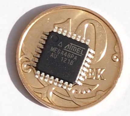
- AVR microcontroller, I have ATMega48 in the bins most of all, let it be;
- Clocking from an internal source. The fact is that externally, you can clock the AVR with an arbitrarily low frequency, and this immediately translates our task into the category of non-sports ones;
- We blink a LED with a visible frequency;
- The size of the program should be minimal;
- All the strong power of the microcontroller is thrown to the task.
For the display, let's connect the LED with a resistor between the V CC power bus and the B7 pin of our little mega.
We will write in AVR Studio.
In order not to rush immediately into the jungle of asm, we first present the obvious pseudocode in C:
int main(void) { volatile uint16_t x; while (1) { // while (++x) // ; DDRB ^= (1 << PB7); // B7 } } Since we do not need to be distracted by other tasks, the use of timers is clearly redundant. The usual for GCC delay function _delay_us () is based on something like the internal while loop here. We immediately treated the variable x badly - we make a cycle based on its overflow, which is unacceptable in real tasks.
We look at the listing, we are terrified of the compiler's extravagance and create a project based on an assembler. Throwing out the superfluous from the compiler remains:
.include "m48def.inc" ; ATMega48 .CSEG ; ldi r16, 0x80 ; r16 = 0x80 start: adiw x, 1 ; [r26:r27] 1 brcc start ; , in r28, DDRB ; r28 = DDRB eor r28, r16 ; r28 ^= r16 out DDRB, r28 ; DDRB = r28 rjmp start ; goto start For non-use of interrupts, we place the code right in the place of the table of these, since the Reset will lead us to the address 0x0000. When x goes from 0xFFFF to 0x0000, the carry flags (overflow) C and the zero result flag Z are set up; you can catch any one using brne or brcc.
We got 14 bytes of machine code and the cycle time of the counter = 4 clock cycles. Since the x is two-byte, the half-blinking of the LED is 65536 * 4 = 262144 cycles. Let's select the internal timer more slowly, namely the 128 kHz RC oscillator. Then our half period is 262144/128000 = 2.048 s. The conditions of the task are fulfilled, but the size of the firmware can obviously be reduced.
First, we sacrifice reading the status of the direction of the DDRB port, why we need it, we already know that there is always either 0x00 or 0x80. Yes, this is not good, but here we have everything under control! And secondly, the rest of the findings of port B are not used, it's okay if there will be trash written there!
Let's pay attention to the high-order bit of the variable x : it changes strictly after 65536/2 * 4 = 131072 cycles. Well, we will output its high byte xh to the port, getting rid of the internal loop and the variable r16 :
start: adiw x, 1 ; [r26:r27] 1 out DDRB, xh ; DDRB = r27 rjmp start ; goto start Perfectly! We did it in 6 bytes! Calculate the timings: (2 + 1 + 2) * 65536/2 = 163840, which means the LED will flash with a half period of 163840/128000 = 1.28 s. The remaining legs of port B will twitch much faster, we just close our eyes to this.
And on this one could calm down, however, a real assembler has an even dirtier trick up his sleeve than all the previous ones taken together! Why don't we throw away this rjmp, which occupies (think only) a third of the program? Turn to the depths. After erasing the microcontroller's flash memory, all cells take the value 0xFF, that is, after the processor goes beyond the program, only instructions 0xFFFF come across to them, they are undocumented, but they are executed in the same way as 0x0000 (nop), namely, the processor does not does nothing but increase the register register of the instruction being executed (Program counter). After this limit reaches its limit, in our case it is the size of the program memory 4096 - 1 = 4097, it overflows and again becomes equal to 0, indicating the beginning of the program, where the execution goes! Now the delay will be determined by the passage through the entire program memory, these are 2048 two-byte instructions, which are executed one cycle at a time. Therefore, we take a one-byte variable counter:
inc r16 ; r16++ out DDRB, r16 ; DDRB = r16 Or on C:
uint_8 b DDRB = ++b; The half-cycle of the LED blink will be 2048 * 256/2 = 262144 cycles or 2.048 seconds (as in the first example).
Total, the size of our program is 4 bytes , it is functional, however, this victory was achieved at such a price that we are ashamed to look in the mirror. By the way, the size of the original C program was 110 bytes with the -Os compilation option (fast and compact code).
findings
If you get cramped within the language - get down to the bottom, there is nothing complicated. After studying how the processor works, it becomes much easier with top-level languages. Yes, abstraction increase is now in vogue: frameworks, Linux in a coffee maker, even embedded x86, however, the assembler is not going to lose ground when you need hard realtime, maximum performance, limited resources, etc. Despite poor portability (sometimes even within the family), modifiability, ease of losing understanding of what is happening and the complexity of writing large programs, fast and small functions and inserts are quite successfully written in assembly language, and it looks like it cannot be beaten out of this niche ever! Although this is primarily concerned with embeds, in most x86 programmers, assembler is mostly found when debugging, popping out with a frightening listing.
For me, holivara Asm vs C does not exist, I apply them together, while C dominates significantly.
The use of the sword implies utmost attentiveness.
Thanks for attention!
UPD1
Not lazy, poured into iron - yes, it works!
UPD2
But never do this at all!
In view of the fact that the idea of reducing the program does not leave the minds further, we will continue.
I did not try it myself, but some people on the Internet say that if you write to the PINx register, the value of PORTx will change to the opposite (except for the oldest AVR microcontrollers). This means that an internal pull-up resistor is connected / disconnected between V CC and the output.
Take the LED more sensitive to small currents and connect it between the output B0 and the ground.
Let's program the CKDIV8 fusion, the clock frequency will drop another 8 times - up to 16 kHz. (Only now, not every programmer can reprogram the microcontroller, for example, the original AVRISP mkII can, but I cannot vouch for its clones).
We bring the program to 1 command ( 2 bytes ):
sbi PINB, 0 ; PINB = 0x01 PORTB ^= 0x01 Stitch, and we see in the dark a flicker. The frequency is 16000/2049/2 ≈ 4 Hz. For a microcontroller with a larger amount of flash-memory, this frequency will be, respectively, less - up to the full blink.
UPD3
Moving on.
Can the AVR microcontroller signal its work without a program at all?
Of course! It is enough to program the CKOUT fusion, and then the CLKO pin (PB0 again) will generate a clock signal, including an internal one, and if its frequency is reduced by the prescaler, then a slower one will be output.
So erase the crystal, do not write our program to 0 bytes , flush the fuses. But giving 16 kHz to a LED with a resistor makes little sense, although we note that it lit up with half brightness.
However, besides the visual low-frequency Hello World, there is a high-frequency audible! This option, of course, does not correspond to our initial TZ, but it signals fully about the work of the MC. We cling the piezoelement between the output B0 and the ground or the power bus, and “enjoy” the nasty squeak.
Source: https://habr.com/ru/post/240517/
All Articles