Arduino programming with ArduBloсk using the example of a robot moving along a strip
Hello! I am Alikin Alexander Sergeevich, a teacher of additional education, I lead the circles "Robotics" and "Radio Engineering" in the Center for Central Labor Rights Education in Labinsk. I would like to talk a little bit about the simplified method of programming Arduino using the ArduBlok program.
I introduced this program to the educational process and I admire the result; it is in special demand for children, especially when writing the simplest programs or for creating some initial stage of complex programs. ArduBlok is a graphical programming environment, that is, all actions are performed with drawn pictures with signed actions in Russian, which greatly simplifies the study of the Arduino platform. Children from 2nd grade can easily work with Arduino thanks to this program.
Yes, someone can say that Scratch still exists and it is also a very simple graphical environment for programming Arduino. But Scratch does not flash Arduino, but only controls it with a USB cable. Arduino is computer dependent and cannot work autonomously. When creating your own projects, autonomy for Arduino is the main thing, especially when creating robotic devices.
')
Even the well-known LEGO robots, such as NXT or EV3, are no longer so interesting for our students with the introduction of the ArduBlok program in Arduino programming. Even Arduino is much cheaper than any LEGO constructors and many components can be simply taken from old consumer electronics. The ArduBlok program will help in the work not only for beginners, but also for active users of the Arduino platform.
So what is ArduBlok? As I said, this is a graphical programming environment. Almost completely translated into Russian. But in ArduBlok, the highlight is not only this, but also the fact that the ArduBlok program written by us converts to the Arduino IDE code. This program is built into the Arduino IDE programming environment, i.e. it is a plugin.
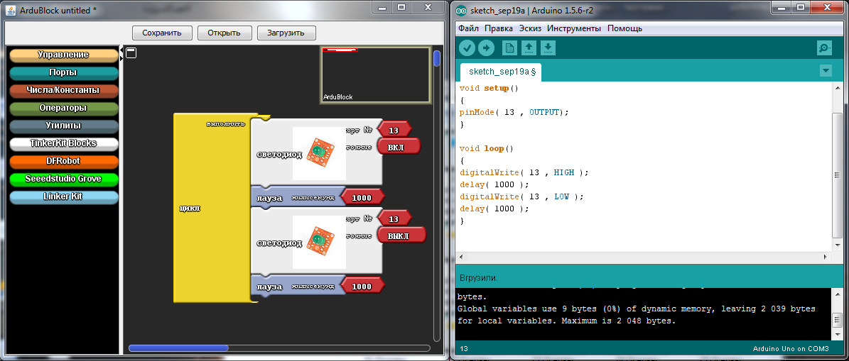
Below is an example of a flashing LED and a converted program in the Arduino IDE. All work with the program is very simple and any student can understand it.
As a result of working on the program, you can not only program Arduino, but also study incomprehensible commands in text-based Arduino IDE, but if you are too lazy to write standard commands, it’s worthwhile to quickly sketch a simple program in ArduBlok, and debug it in Arduino IDE .
To install ArduBlok, you must first download and install the Arduino IDE from the official Arduino site and deal with the settings when working with the Arduino UNO board. How to do this is described on the same site or on Amperk , or look at the vastness of YouTube. Well, when you figure it out, you need to download ArduBlok from the official site, here is the link . I do not recommend downloading the latest versions, they are very difficult for beginners, but the 2013-07-12 version is the most popular one.
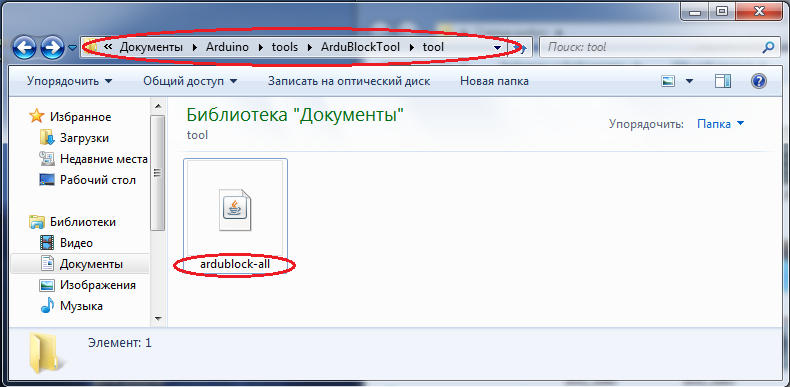
Then, we rename the downloaded file to ardublock-all and in the “documents” folder. Create the following folders: Arduino> tools> ArduBlockTool> tool and in the latter we throw the downloaded and renamed file. ArduBlok works on all operating systems, even on Linux, checked it myself personally on XP, Win7, Win8, all examples for Win7. Installation of the program for all systems is the same.
Well, if it's simpler, I prepared an archive on the 7z Mail-disk, unpacking which you will find 2 folders. In one, the Arduino IDE program is already working, and in another folder the contents must be sent to the folder documents.
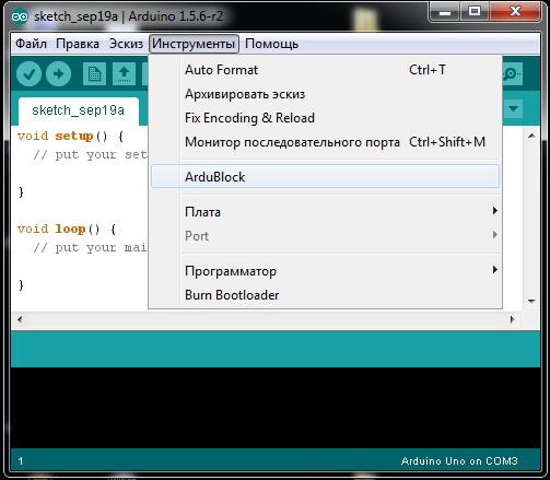
In order to work in ArduBlok, you need to run the Arduino IDE. After that we go to the Tools tab and there we find the ArduBlok item, click on it - and here it is, our goal.
Now let's deal with the interface of the program. As you already understood, there are no settings in it, but there are plenty of programming icons and each of them carries a command in the Arduino IDE text format. In the new versions of the icons even more, so to deal with the latest version of ArduBlok is difficult and some of the icons are not translated into Russian.
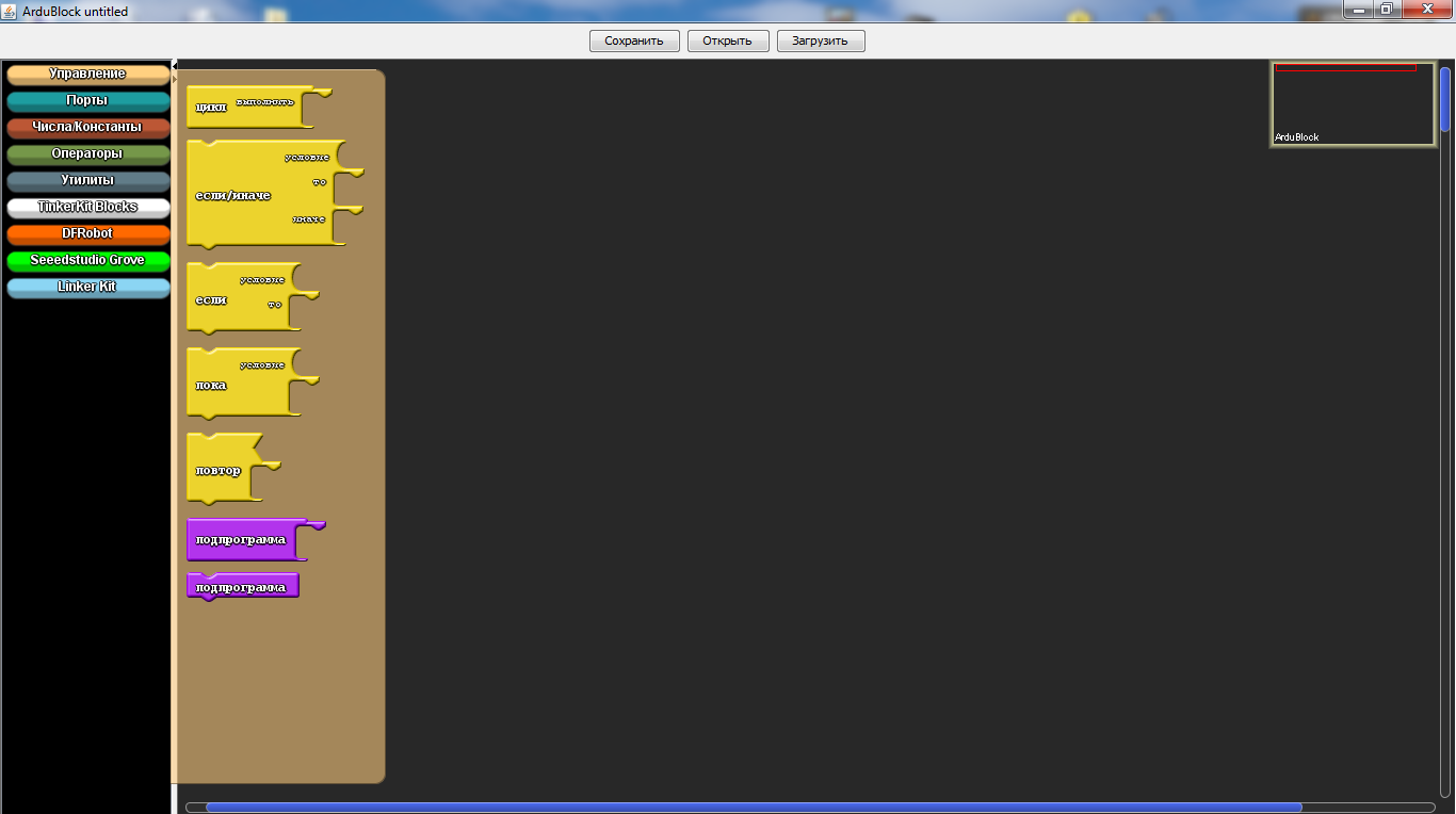
In the section "Management" we will find a variety of cycles.
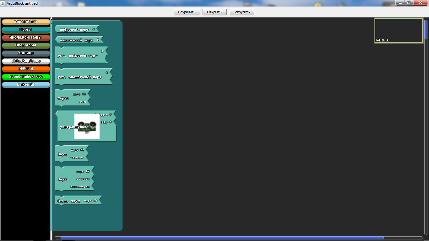
In the “Ports” section we can manage the values of the ports, as well as the sound emitter, servo machine or ultrasonic proximity sensor connected to them.
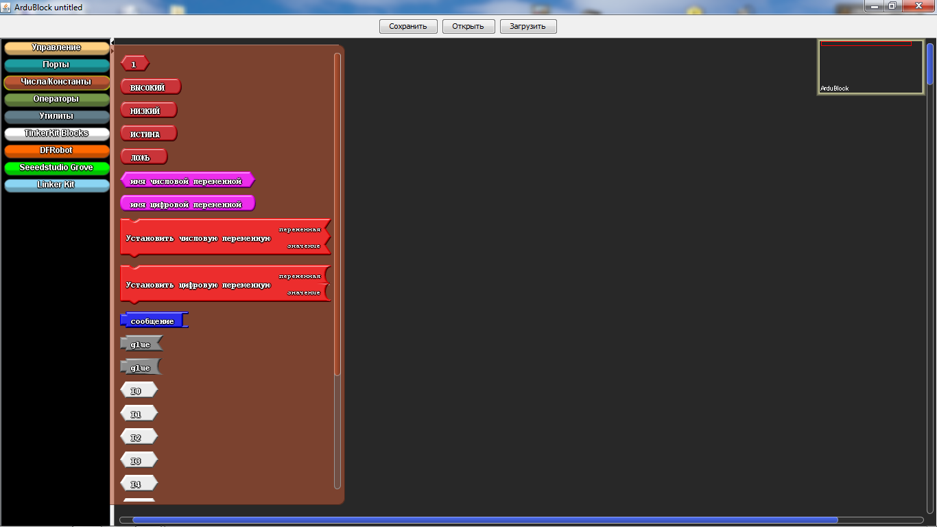
In the "Numbers / Constants" section, we can choose with you numerical values or create a variable, but the one below is unlikely to be used.
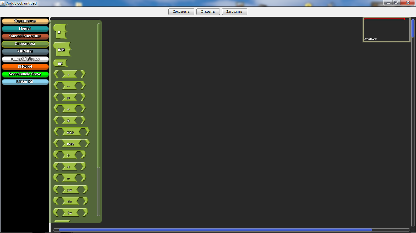
In the section "Operators" we will find all the necessary comparison and calculation operators.
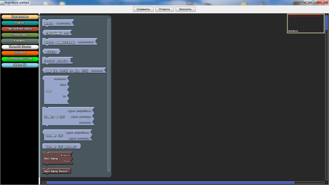
In the “Utilities” section, icons with time are mainly used.

"TinkerKit Bloks" is the section for the purchased sensors of the TinkerKit kit. Of course, we don’t have such a kit, but that doesn’t mean that the icons don’t fit for other sets, quite the contrary - it’s very convenient for guys to use icons such as turning on an LED or a button. These marks are used in almost all programs. But they have a peculiarity - when choosing them, there are incorrect icons indicating the ports, so they must be removed and the icon from the “numbers / constants” section should be the topmost one in the list.
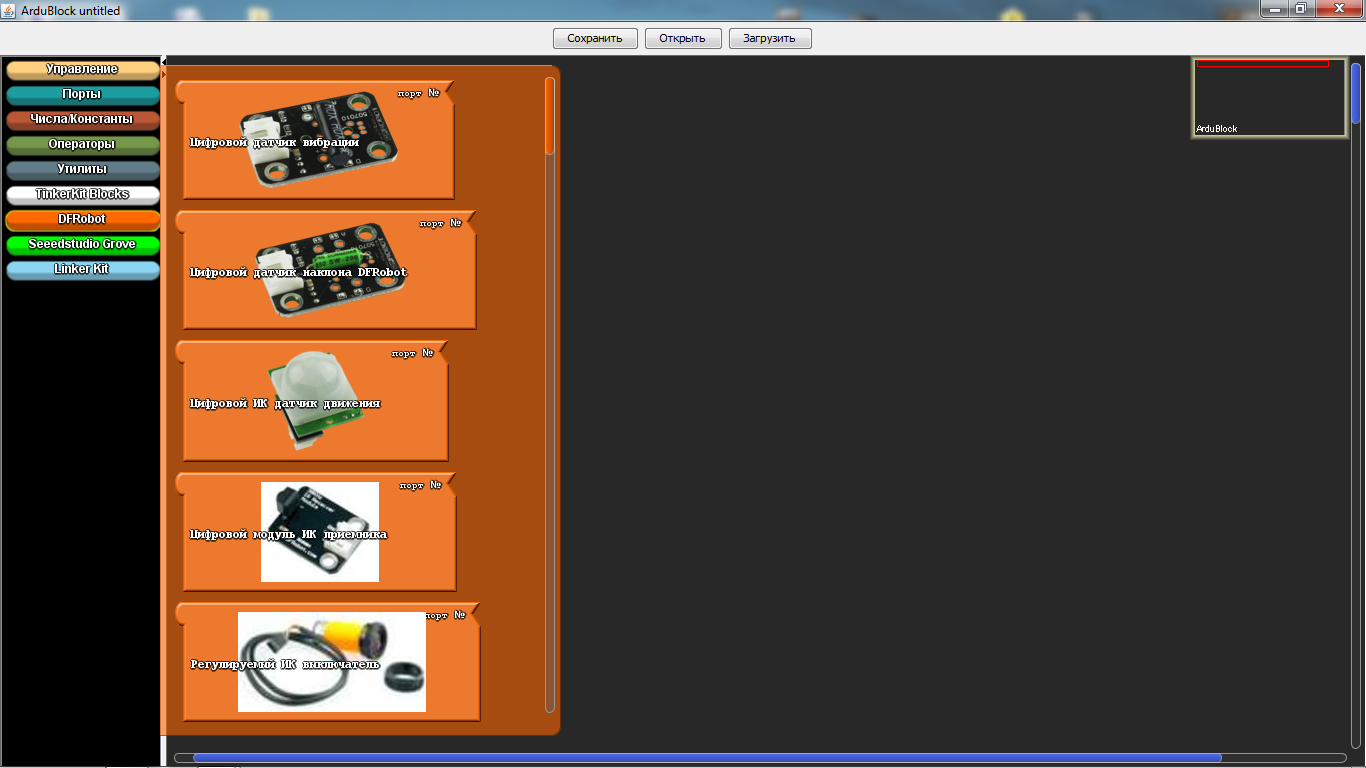
"DF Robot" - this section is used in the presence of sensors specified in it, they are sometimes found. And our today's example is not an exception, we have "Adjustable IR switch" and "Line sensor". "Line sensor" is different from what is in the picture, as it is from the firm of Amperk. Their actions are identical, but the sensor from Amperki is much better, since it has a sensitivity regulator.
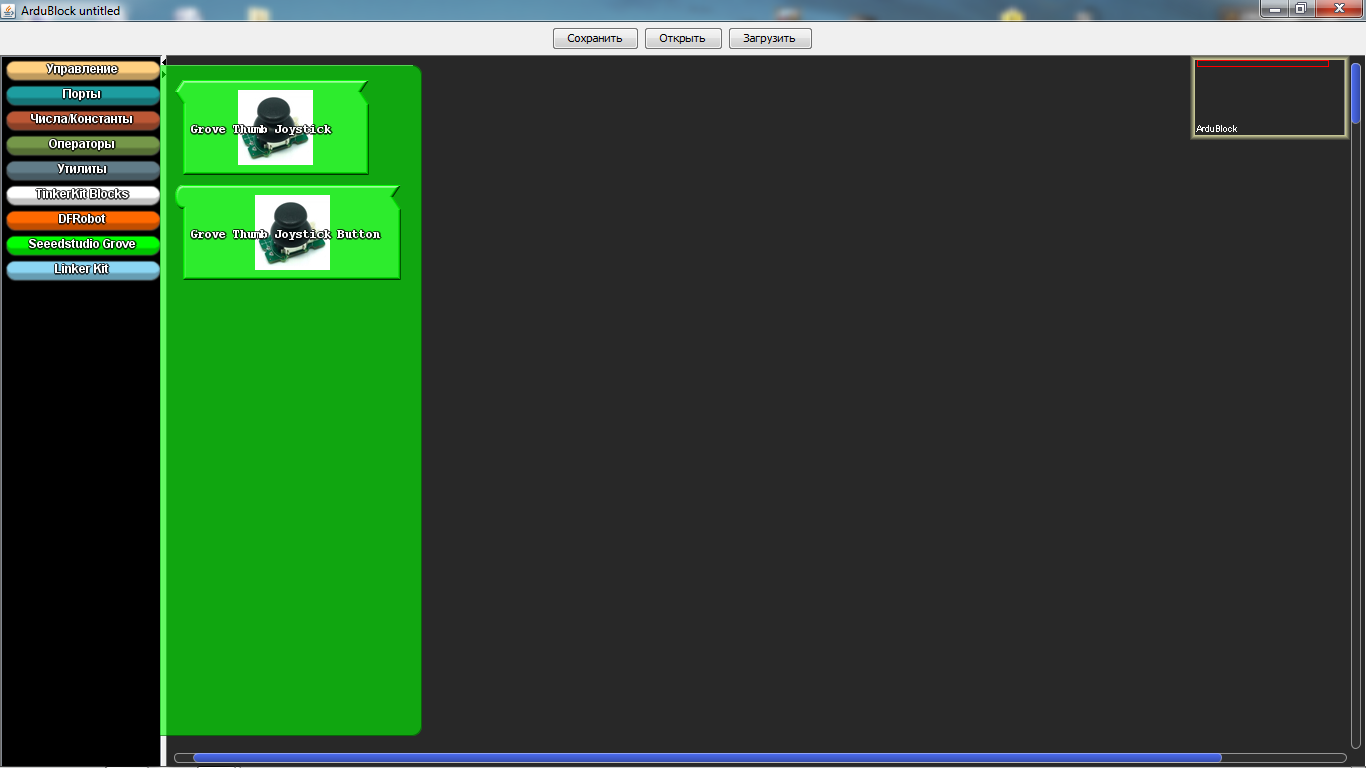
“Seeedstudio Grove” - the sensors of this section have never been used by me, although there are only joysticks. In new versions, this section is expanded.
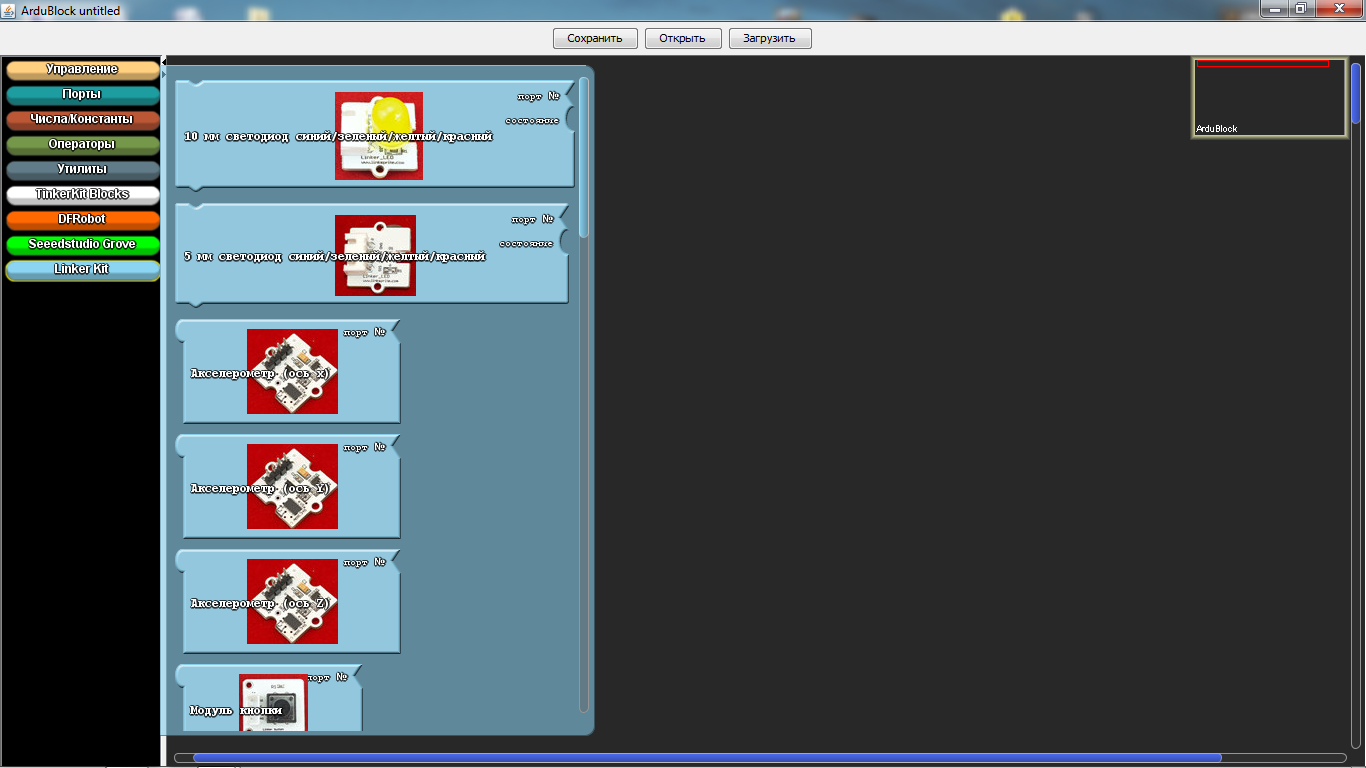
And the last section is the “Linker Kit”. The sensors presented in it, I did not come across.
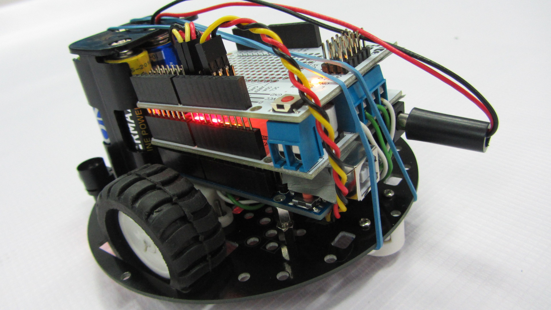
I would like to show an example of a program on a robot moving along a strip. The robot is very simple, both in the assembly and in the acquisition, but first things first. Let's start with its acquisition and assembly.
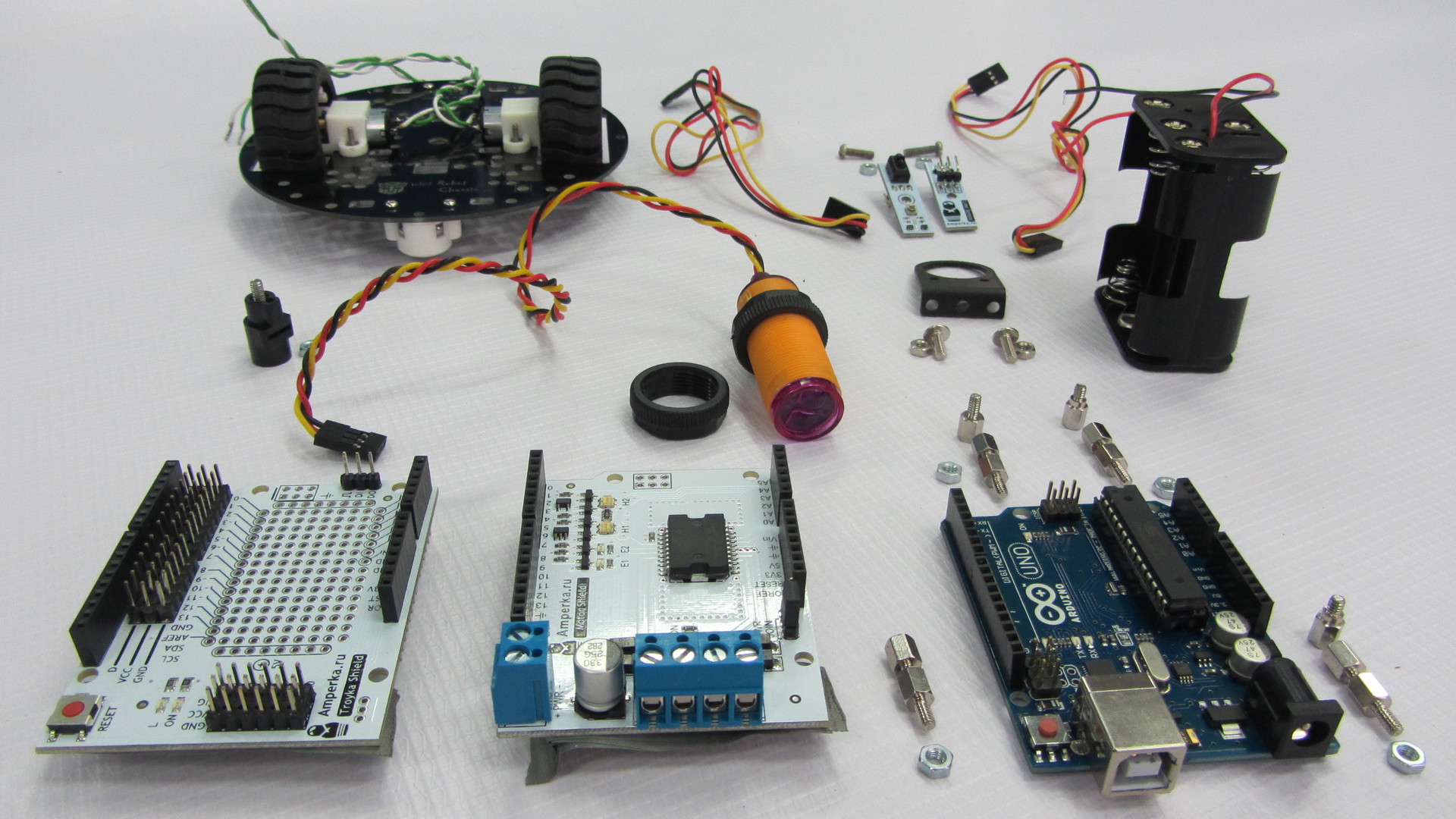
Here the set of parts was all purchased on the site of Amperk .
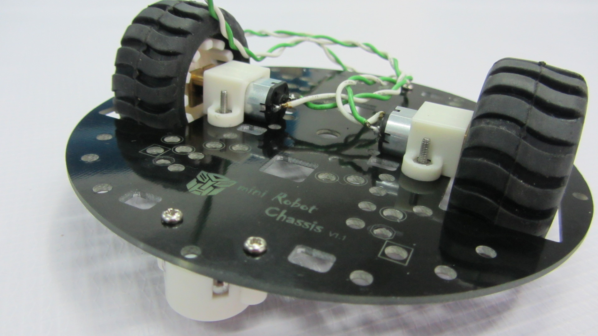
To begin, we will assemble a wheeled platform and solder wires to the engines.
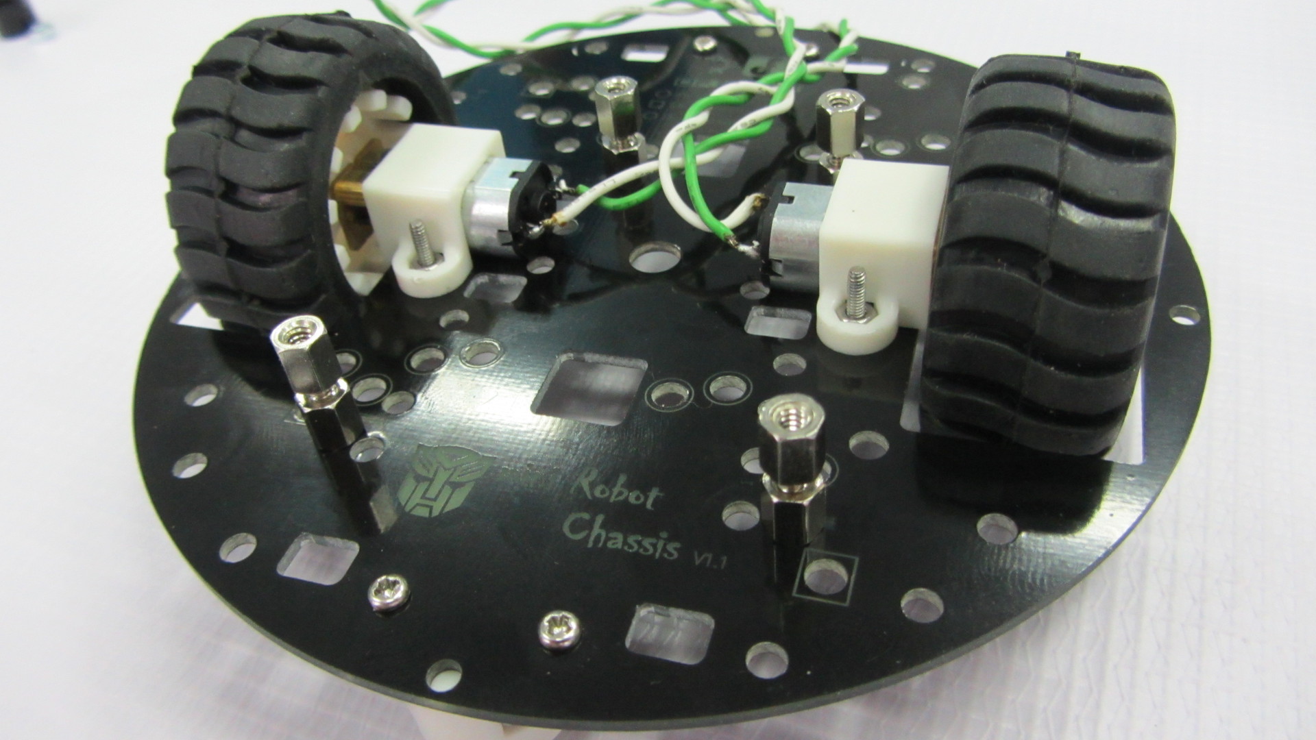
Then we will install racks for fastening the Arduino UNO board, which were taken from the old motherboard or other similar fasteners.
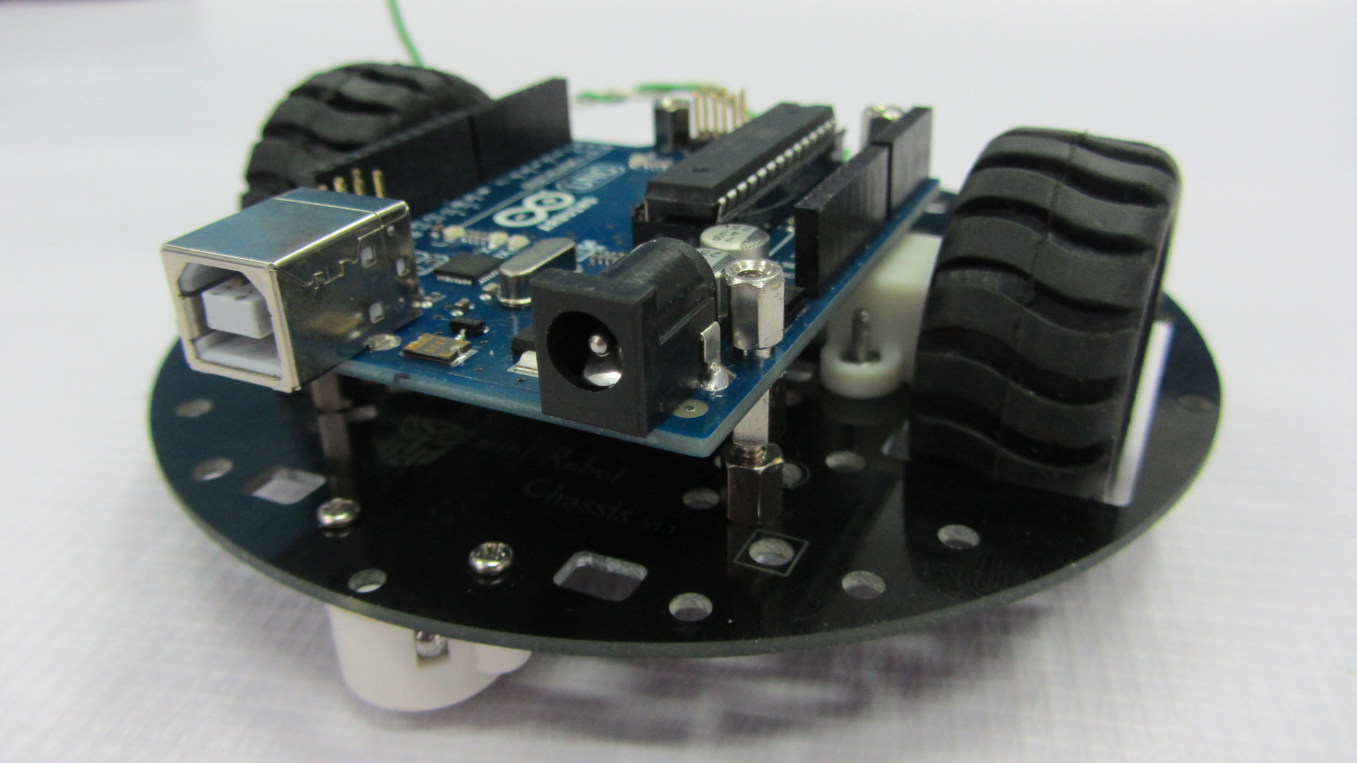
Then we fasten the Arduino UNO board on these racks, but one bolt cannot be screwed in - the connectors interfere. You can, of course, drop them, but this is up to you.
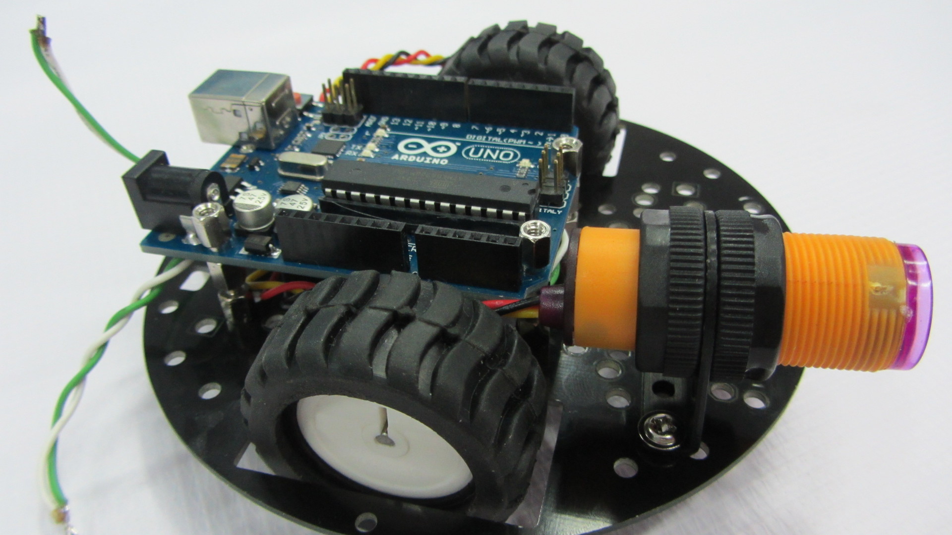
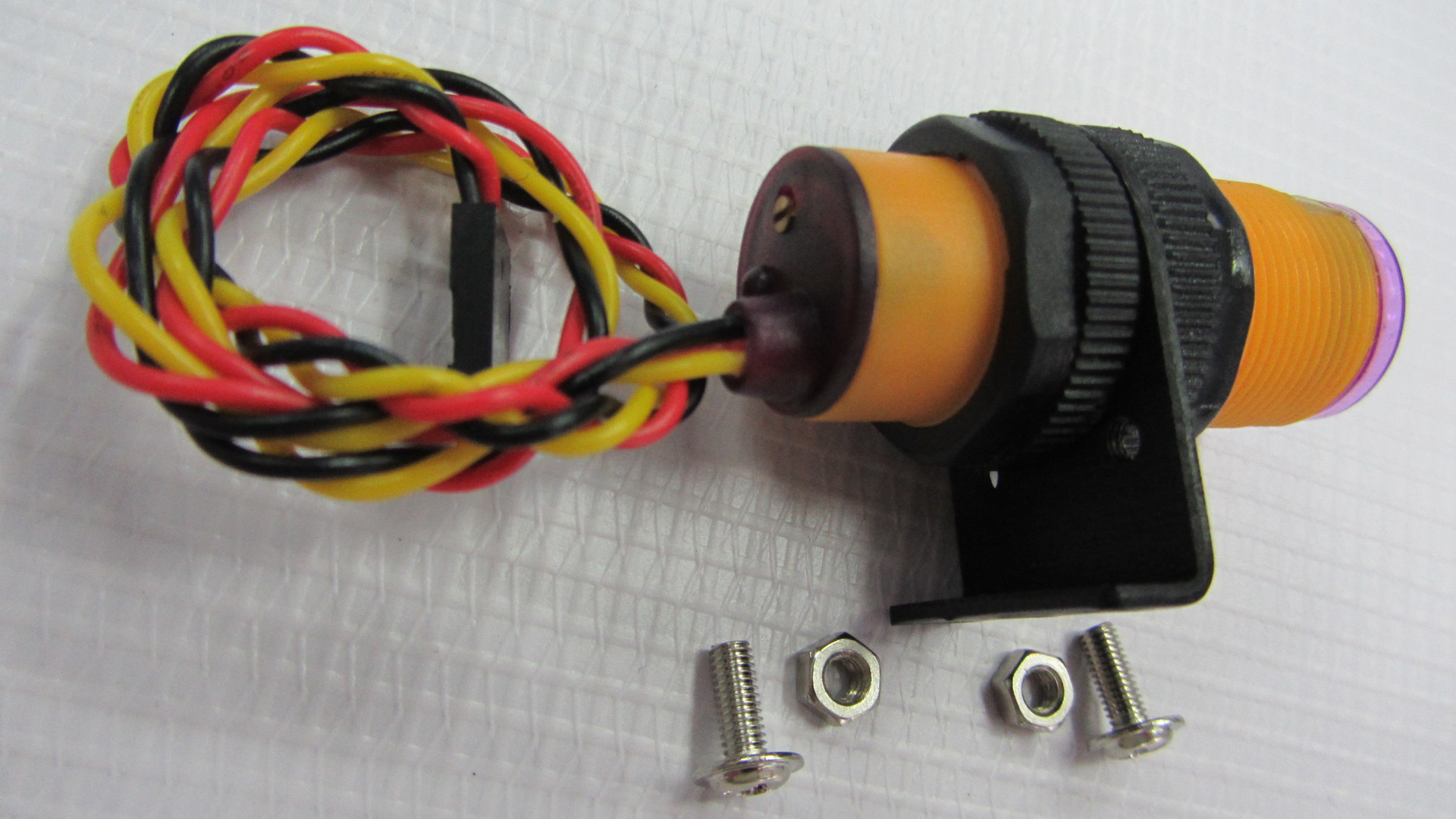
Next we fix the infrared sensor of the obstacles on its special mount. Please note that the sensitivity control is on top, this is for easy adjustment.
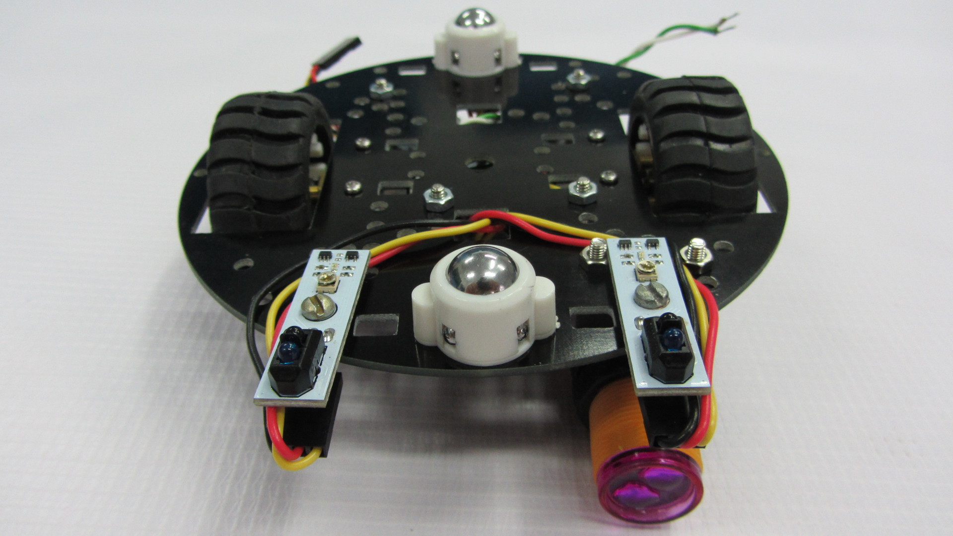
Now we install digital line sensors, then we have to look for a couple of bolts and 4 nuts for them. We install two nuts between the platform itself and the line sensor, and fix the rest of the sensors.
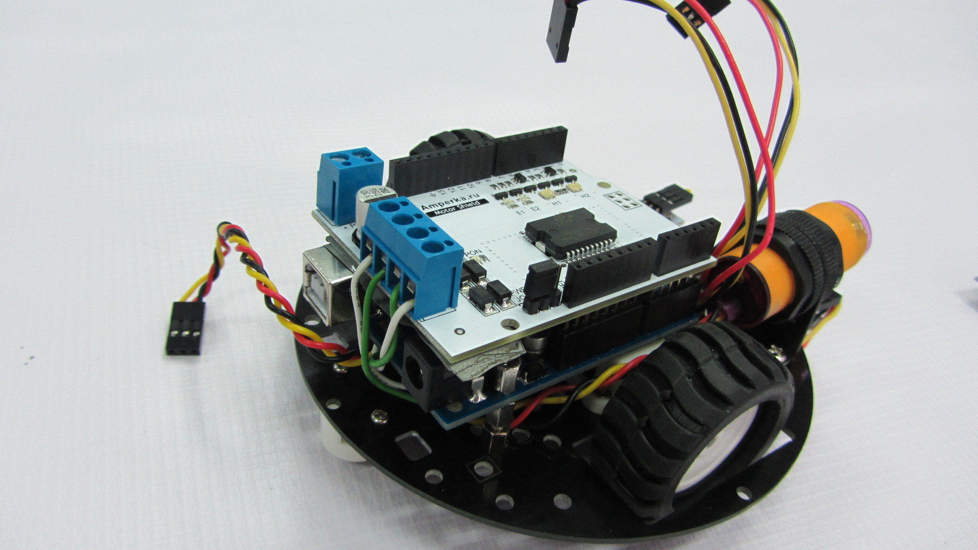
The next install Motor Shield or otherwise you can call the engine driver. In our case, pay attention to the jumper. We will not use a separate power supply for the engines, so it is set to this position. The bottom part is sealed with tape, so that there are no accidental closures from the USB connector of the Arduino UNO, this is just in case.
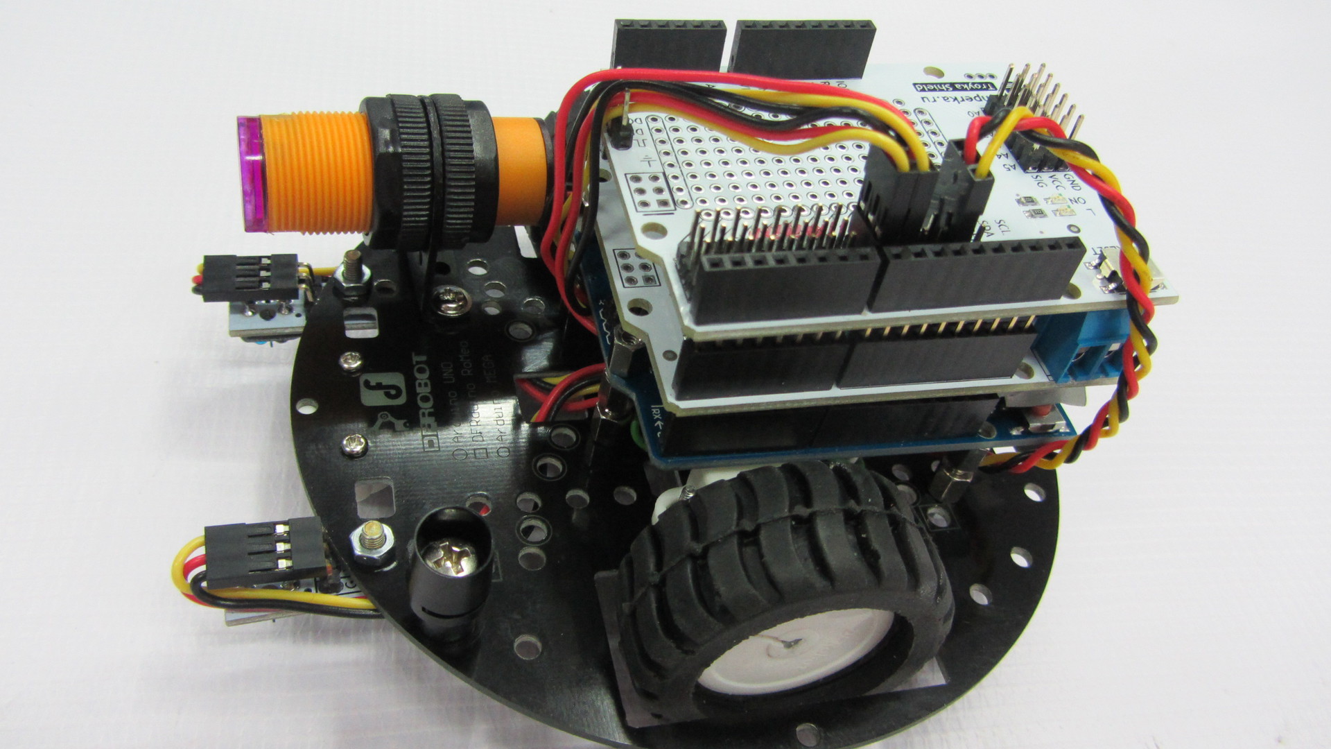
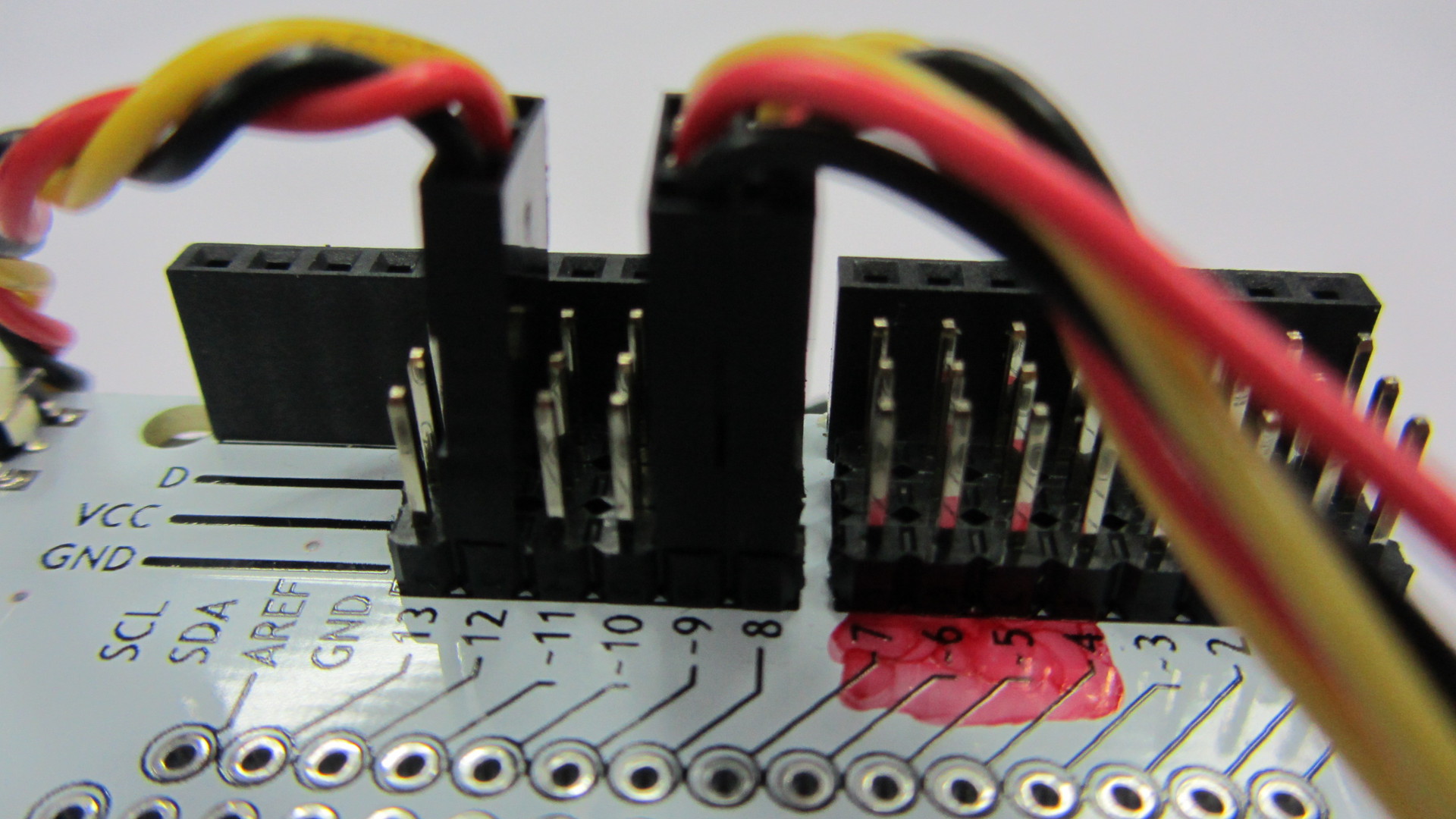
On top of the Motor Shield install Troyka Shield. It is necessary for the convenience of connecting sensors. All the sensors we use are digital, so the line sensors are connected to port 8 and 9, as they are also called pins, and the infrared obstacle sensor is connected to port 12. Be sure to note that you cannot use ports 4, 5, 6, 7 as they are used by Motor Shield to control engines. I even specially painted these ports with a red marker so that the students could understand.
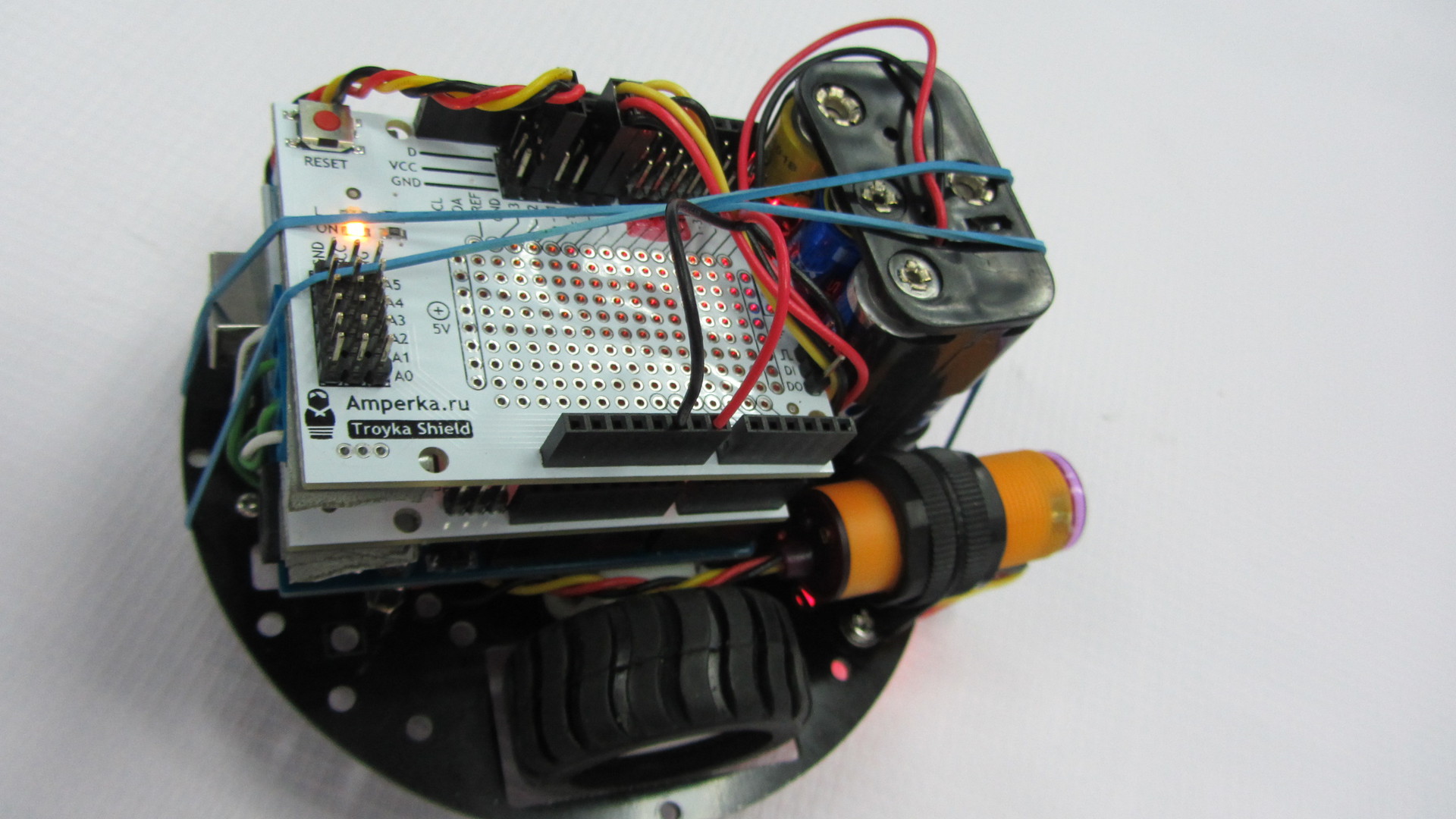
If you have already noticed, I added a black sleeve, just in case that the battery compartment installed by us does not fly out. And finally, we fix the entire structure with an ordinary rubber band.
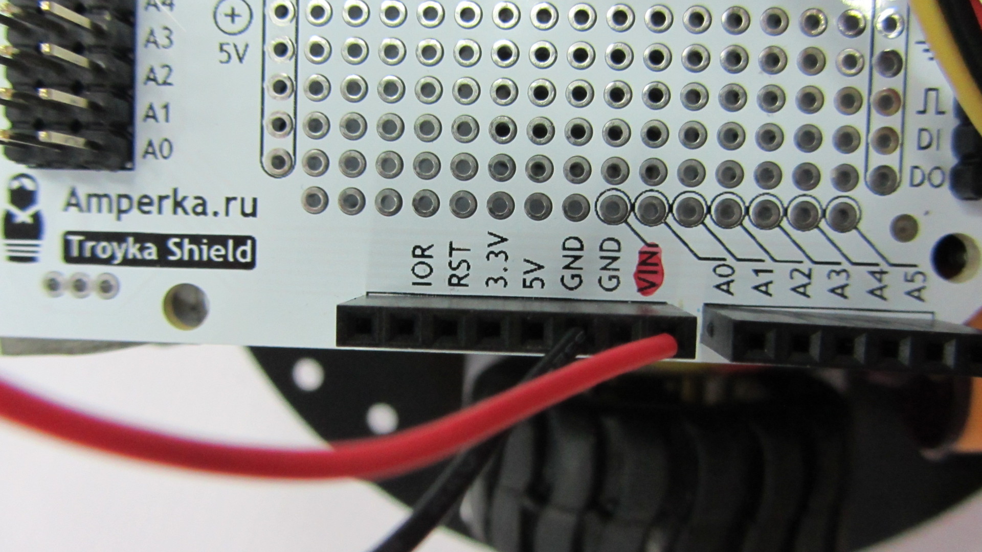
Connecting the battery compartment can be of 2 types. First wire connection to Troyka Shield. It is also possible to solder the power plug and connect it to the Arduino UNO board itself.
Here is our robot ready. Before starting to program, it will be necessary to study how everything works, namely:
- Motors:
Port 4 and 5 are used to control one motor, and 6 and 7 others;
The speed of rotation of the engine, we are adjusting the PWM on ports 5 and 6;
Forward or backward, sending signals to ports 4 and 7.
- Sensors:
We are all digital, so they give logical signals in the form of 1 or 0;
And in order to adjust them, they have special regulators, and you can calibrate them with a suitable screwdriver.
Details can be found on Ampere . Why here? Because there is a lot of information on working with Arduino.
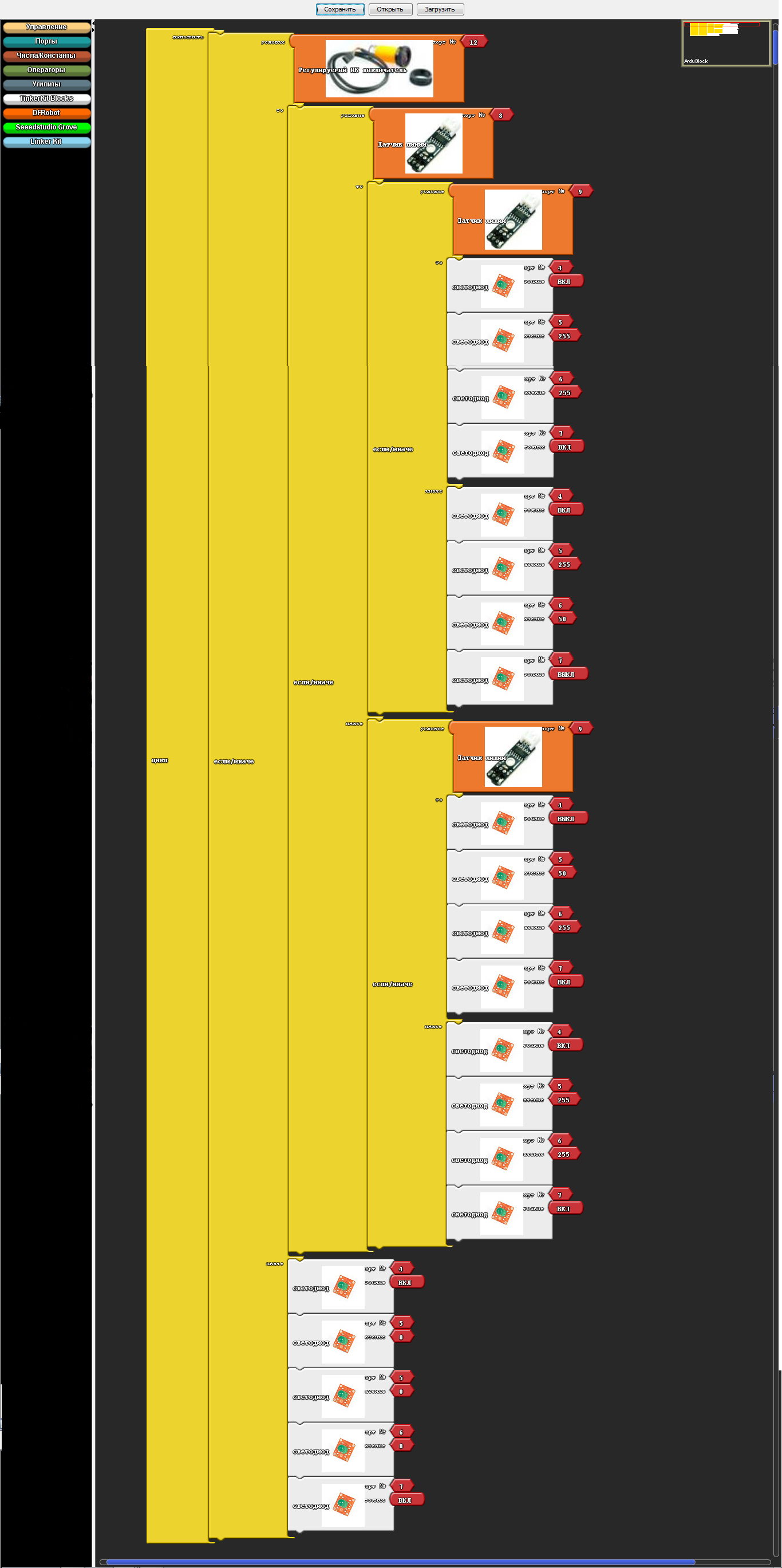
Well, we, perhaps, looked at everything superficially, studied and of course collected the robot. Now it is necessary to program it, here it is - the long-awaited program!
And the program converted to Arduino IDE:
In conclusion, I want to say this program is just a godsend for education, even for self-study it will help you learn the commands of the Arduino IDE. The most important highlight is that with more than 50 installation icons, it starts to “glitch”. Yes, indeed, this is a highlight, since constant programming only on ArduBlok does not teach you how to program in the Arduino IDE. The so-called "glitch" gives you the opportunity to think and try to memorize commands for accurate debugging programs.
I wish you success.
I introduced this program to the educational process and I admire the result; it is in special demand for children, especially when writing the simplest programs or for creating some initial stage of complex programs. ArduBlok is a graphical programming environment, that is, all actions are performed with drawn pictures with signed actions in Russian, which greatly simplifies the study of the Arduino platform. Children from 2nd grade can easily work with Arduino thanks to this program.
Yes, someone can say that Scratch still exists and it is also a very simple graphical environment for programming Arduino. But Scratch does not flash Arduino, but only controls it with a USB cable. Arduino is computer dependent and cannot work autonomously. When creating your own projects, autonomy for Arduino is the main thing, especially when creating robotic devices.
')
Even the well-known LEGO robots, such as NXT or EV3, are no longer so interesting for our students with the introduction of the ArduBlok program in Arduino programming. Even Arduino is much cheaper than any LEGO constructors and many components can be simply taken from old consumer electronics. The ArduBlok program will help in the work not only for beginners, but also for active users of the Arduino platform.
So what is ArduBlok? As I said, this is a graphical programming environment. Almost completely translated into Russian. But in ArduBlok, the highlight is not only this, but also the fact that the ArduBlok program written by us converts to the Arduino IDE code. This program is built into the Arduino IDE programming environment, i.e. it is a plugin.
Below is an example of a flashing LED and a converted program in the Arduino IDE. All work with the program is very simple and any student can understand it.
As a result of working on the program, you can not only program Arduino, but also study incomprehensible commands in text-based Arduino IDE, but if you are too lazy to write standard commands, it’s worthwhile to quickly sketch a simple program in ArduBlok, and debug it in Arduino IDE .
To install ArduBlok, you must first download and install the Arduino IDE from the official Arduino site and deal with the settings when working with the Arduino UNO board. How to do this is described on the same site or on Amperk , or look at the vastness of YouTube. Well, when you figure it out, you need to download ArduBlok from the official site, here is the link . I do not recommend downloading the latest versions, they are very difficult for beginners, but the 2013-07-12 version is the most popular one.
Then, we rename the downloaded file to ardublock-all and in the “documents” folder. Create the following folders: Arduino> tools> ArduBlockTool> tool and in the latter we throw the downloaded and renamed file. ArduBlok works on all operating systems, even on Linux, checked it myself personally on XP, Win7, Win8, all examples for Win7. Installation of the program for all systems is the same.
Well, if it's simpler, I prepared an archive on the 7z Mail-disk, unpacking which you will find 2 folders. In one, the Arduino IDE program is already working, and in another folder the contents must be sent to the folder documents.
In order to work in ArduBlok, you need to run the Arduino IDE. After that we go to the Tools tab and there we find the ArduBlok item, click on it - and here it is, our goal.
Now let's deal with the interface of the program. As you already understood, there are no settings in it, but there are plenty of programming icons and each of them carries a command in the Arduino IDE text format. In the new versions of the icons even more, so to deal with the latest version of ArduBlok is difficult and some of the icons are not translated into Russian.
In the section "Management" we will find a variety of cycles.
In the “Ports” section we can manage the values of the ports, as well as the sound emitter, servo machine or ultrasonic proximity sensor connected to them.
In the "Numbers / Constants" section, we can choose with you numerical values or create a variable, but the one below is unlikely to be used.
In the section "Operators" we will find all the necessary comparison and calculation operators.
In the “Utilities” section, icons with time are mainly used.
"TinkerKit Bloks" is the section for the purchased sensors of the TinkerKit kit. Of course, we don’t have such a kit, but that doesn’t mean that the icons don’t fit for other sets, quite the contrary - it’s very convenient for guys to use icons such as turning on an LED or a button. These marks are used in almost all programs. But they have a peculiarity - when choosing them, there are incorrect icons indicating the ports, so they must be removed and the icon from the “numbers / constants” section should be the topmost one in the list.
"DF Robot" - this section is used in the presence of sensors specified in it, they are sometimes found. And our today's example is not an exception, we have "Adjustable IR switch" and "Line sensor". "Line sensor" is different from what is in the picture, as it is from the firm of Amperk. Their actions are identical, but the sensor from Amperki is much better, since it has a sensitivity regulator.
“Seeedstudio Grove” - the sensors of this section have never been used by me, although there are only joysticks. In new versions, this section is expanded.
And the last section is the “Linker Kit”. The sensors presented in it, I did not come across.
I would like to show an example of a program on a robot moving along a strip. The robot is very simple, both in the assembly and in the acquisition, but first things first. Let's start with its acquisition and assembly.
Here the set of parts was all purchased on the site of Amperk .
- AMP-B001 Motor Shield (2 channels, 2 A) 1,890 rub
- AMP-B017 Troyka Shield 1 690 rub
- AMP-X053 Battery compartment 3 × 2 AA 1 60 rub
- AMP-B018 Digital Line Sensor 2 580 rub
- ROB0049 Two-wheel platform miniQ 1 1890 rub
- SEN0019 Infrared Obstacle Sensor 1 390 rub
- FIT0032 Mounting for infrared obstacle sensor 1 90 rub
- A000066 Arduino Uno 1 1150 rub
To begin, we will assemble a wheeled platform and solder wires to the engines.
Then we will install racks for fastening the Arduino UNO board, which were taken from the old motherboard or other similar fasteners.
Then we fasten the Arduino UNO board on these racks, but one bolt cannot be screwed in - the connectors interfere. You can, of course, drop them, but this is up to you.
Next we fix the infrared sensor of the obstacles on its special mount. Please note that the sensitivity control is on top, this is for easy adjustment.
Now we install digital line sensors, then we have to look for a couple of bolts and 4 nuts for them. We install two nuts between the platform itself and the line sensor, and fix the rest of the sensors.
The next install Motor Shield or otherwise you can call the engine driver. In our case, pay attention to the jumper. We will not use a separate power supply for the engines, so it is set to this position. The bottom part is sealed with tape, so that there are no accidental closures from the USB connector of the Arduino UNO, this is just in case.
On top of the Motor Shield install Troyka Shield. It is necessary for the convenience of connecting sensors. All the sensors we use are digital, so the line sensors are connected to port 8 and 9, as they are also called pins, and the infrared obstacle sensor is connected to port 12. Be sure to note that you cannot use ports 4, 5, 6, 7 as they are used by Motor Shield to control engines. I even specially painted these ports with a red marker so that the students could understand.
If you have already noticed, I added a black sleeve, just in case that the battery compartment installed by us does not fly out. And finally, we fix the entire structure with an ordinary rubber band.
Connecting the battery compartment can be of 2 types. First wire connection to Troyka Shield. It is also possible to solder the power plug and connect it to the Arduino UNO board itself.
Here is our robot ready. Before starting to program, it will be necessary to study how everything works, namely:
- Motors:
Port 4 and 5 are used to control one motor, and 6 and 7 others;
The speed of rotation of the engine, we are adjusting the PWM on ports 5 and 6;
Forward or backward, sending signals to ports 4 and 7.
- Sensors:
We are all digital, so they give logical signals in the form of 1 or 0;
And in order to adjust them, they have special regulators, and you can calibrate them with a suitable screwdriver.
Details can be found on Ampere . Why here? Because there is a lot of information on working with Arduino.
Well, we, perhaps, looked at everything superficially, studied and of course collected the robot. Now it is necessary to program it, here it is - the long-awaited program!
And the program converted to Arduino IDE:
void setup() { pinMode( 8 , INPUT); pinMode( 12 , INPUT); pinMode( 9 , INPUT); pinMode( 4 , OUTPUT); pinMode( 7 , OUTPUT); pinMode(5, OUTPUT); pinMode(6, OUTPUT); } void loop() { if (digitalRead( 12)) { if (digitalRead( 8)) { if (digitalRead( 9)) { digitalWrite( 4 , HIGH ); analogWrite(5, 255); analogWrite(6, 255); digitalWrite( 7 , HIGH ); } else { digitalWrite( 4 , HIGH ); analogWrite(5, 255); analogWrite(6, 50); digitalWrite( 7 , LOW ); } } else { if (digitalRead( 9)) { digitalWrite( 4 , LOW ); analogWrite(5, 50); analogWrite(6, 255); digitalWrite( 7 , HIGH ); } else { digitalWrite( 4 , HIGH ); analogWrite(5, 255); analogWrite(6, 255); digitalWrite( 7 , HIGH ); } } } else { digitalWrite( 4 , HIGH ); analogWrite(5, 0); analogWrite(6, 0); digitalWrite( 7 , HIGH ); } } In conclusion, I want to say this program is just a godsend for education, even for self-study it will help you learn the commands of the Arduino IDE. The most important highlight is that with more than 50 installation icons, it starts to “glitch”. Yes, indeed, this is a highlight, since constant programming only on ArduBlok does not teach you how to program in the Arduino IDE. The so-called "glitch" gives you the opportunity to think and try to memorize commands for accurate debugging programs.
I wish you success.
Source: https://habr.com/ru/post/240441/
All Articles