Small Hello World for a small microcontroller - at 24 bytes (and someone else's decision at 12 bytes)
The classic test program for most programmers on systems with at least some display is Hello World. This tradition was introduced by Kernigan and Ritchie in 1978.
For microcontrollers, a similar example has long been a program that flashes an LED. In this article, I will show the result of an experiment to minimize such a program using the example of the Atmel ATTiny15 controller.

')
UPD: In the comments resulted in a link to a record solution of 12 bytes . Bravo!
UPD2: Through violence against the controller, managed to win another 2 bytes.
UPD3: And another solution , with even more violence against the controller.
UPD4: Another option is in one instruction (but the entire program memory is executed), as in variants 2 and 3.
UPD5: Option using the ability to issue a clock generator to one of the pins of the controller using the FUSE bit
The controller features are small. Clock frequency - 1.6 MHz from the internal generator. There are only five free outputs that can be used without giving up the possibility of a hardware reset and flashing on SPI. There are two timers and ADC. Memory - 64 bytes EEPROM. There is no RAM, only 32 general-purpose registers and a stack whose depth cannot be more than three. AVR-GCC refuses to work with such a controller - offers to use the assembler.

The operating system is Open Suse Linux 13.1. Development environment - AVR Studio 4.12, runs under Wine. Programmer - USBASP running AVRDUDE. The programmer is directly connected to the controller, giving it power during the firmware and during the experiments.
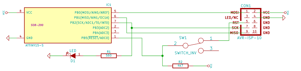
The controller reset signal is inverted - high level means normal operation, low - reset. The RESET signal of almost all AVRs is connected through the first leg of the controller. In addition to the ability to reset the controller, this signal plays a decisive role in the process of in-circuit programming, so it starts up the programmer. By reconfiguring the FUSE bits, it is possible to turn this controller output into a general-purpose output — the controller will no longer be reset by a signal from it, but it will not be programmed without a so-called high-voltage programmer.
USBASP keeps a low level on this pin all the time, preventing the controller from working while the programmer is connected. For ease of debugging, you need to either programmatically (by understanding the USBASP API), or by hardware to be able to pick up the RESET controller. I chose the hardware option in the form of a switch, as the most easily achievable.
Even such a simple thing, as the issuance of rectangular pulses on a particular leg of the controller when working with an assembler turns into a fascinating search for the optimal solution. The undoubted advantage is that the programmer does not depend on the whims of the operating system and the compiler, so he can control the equipment as he sees fit.
The banal implementation of the delay consists in organizing a cycle of empty instructions in which the controller will rotate between the pin switchings. This is a classic delay_ms, so beloved by arduinschiki. There are two minuses here at least: a short minus - the controller will not be able to put to sleep, a long one - the controller will not be able to perform other tasks. Indeed, any interruption will lead to the fact that the number of ticks carefully calculated for the delay will not provide it any more: the time spent by the controller in the handler will be added to the delay time. You can, of course, provide a correction in the handler, and then a correction correction (if there is a branch with branches of different lengths in the handler) - you end up with a very complicated code, which is rather difficult to prove about the correctness of it.
That is why any delays should be implemented on timers. The ATTiny15 controller has two such timers. Both timers can read up to 255, and then issue an interrupt request. The clock source for the timers can be an external signal or a divider of the internal clock generator. The divider allows you to get fractional frequencies from the clock - F / 1, F / 8, F / 64, F / 256, F / 1024. By default, the controller operates at 1.6 MHz, if we use the divider by 1024, we get the timer increment frequency 1562.5 Hz. Since the interrupt timer will be issued for every 256th increment, we will get an additional division by 256 and a total frequency of about 6 Hz. It is quite acceptable for flashing LED.
At the beginning of the firmware, all AVRs should have transition instructions to interrupt handlers. This is very similar to the x86 state of affairs, but they do not store instructions at the beginning of memory, but addresses of handlers.
ATTiny15 should have nine such instructions. The first handler, for example, is the reset handler, in fact, the entry point to the firmware.
In place of the missing handlers, there are return-from-interrupt instructions. But they will never be called - the corresponding interruption is prohibited. That is, these four pieces of
The job of the program is to configure a predivider for a timer,
enable interrupt timer
enable interrupt handling by the processor
switching the pin 7 of the controller to the push-pull mode,
and hang in an infinite loop
Interrupt processing consists of inverting the register and outputting this value to the controller's foot.
After the assembly, we received 40 bytes of machine code:

The idea lies on the surface - since only reset and timer work from interrupts, the controller will never be on other cells of the interrupt table - we will borrow these cells with code:

Got 26 bytes, can we?
Let's place the interrupt handler from the timer immediately in its place, getting rid of the transition and saving as much as two bytes:
After the assembly, 24 bytes were obtained:
Since the controller doesn’t do anything except handling the interrupt, it is worthwhile to put down the processor core, leaving the timer running. This is done by the
It is important to remember that after waking up and handling an interrupt, the controller will try to execute the instruction following the SLEEP, which means that sleep should be looped:

Programming in assembler is the most time-consuming way to get programs optimized in size and speed of execution. The most interesting task here is the development of such a compiler and a HLL, which would produce an optimized code (by some criterion) and proof that it is impossible to get the best code on this device.
In the next article - a USART <-> 1wire converter based on the same controller.
Githaba project ;
Edsger Dijkstra. Selected articles ;
Datasheet on the controller ;
Electronics for everyone .
UPD: In the comments resulted in a link to a record solution of 12 bytes .
In short, the idea is to use a watchdog timer and the fact that RON is not reset when resetting.
Here you can of course cling to the fact that the frequency is not the same and the pulses go to three other outputs, but in size this is an undoubted record. Congratulations!
In conjunction with putting a controller to sleep, the watchdog timer is a powerful tool for realizing energy savings. And with it you can use the deepest sleep - Power Down. At the cost of an additional four bytes, we save a couple of microwatts:
And yes, you can do quite a bit of a swig - remove the final loop from the record, getting a solution of 10 bytes.
UPD: In the comments resulted in a link to a record solution of 12 bytes . Bravo!
UPD2: Through violence against the controller, managed to win another 2 bytes.
UPD3: And another solution , with even more violence against the controller.
UPD4: Another option is in one instruction (but the entire program memory is executed), as in variants 2 and 3.
For microcontrollers, a similar example has long been a program that flashes an LED. In this article, I will show the result of an experiment to minimize such a program using the example of the Atmel ATTiny15 controller.
')
UPD: In the comments resulted in a link to a record solution of 12 bytes . Bravo!
UPD2: Through violence against the controller, managed to win another 2 bytes.
UPD3: And another solution , with even more violence against the controller.
UPD4: Another option is in one instruction (but the entire program memory is executed), as in variants 2 and 3.
UPD5: Option using the ability to issue a clock generator to one of the pins of the controller using the FUSE bit
About controller
The controller features are small. Clock frequency - 1.6 MHz from the internal generator. There are only five free outputs that can be used without giving up the possibility of a hardware reset and flashing on SPI. There are two timers and ADC. Memory - 64 bytes EEPROM. There is no RAM, only 32 general-purpose registers and a stack whose depth cannot be more than three. AVR-GCC refuses to work with such a controller - offers to use the assembler.
Tools
The operating system is Open Suse Linux 13.1. Development environment - AVR Studio 4.12, runs under Wine. Programmer - USBASP running AVRDUDE. The programmer is directly connected to the controller, giving it power during the firmware and during the experiments.
Problem - the programmer keeps RESET
The controller reset signal is inverted - high level means normal operation, low - reset. The RESET signal of almost all AVRs is connected through the first leg of the controller. In addition to the ability to reset the controller, this signal plays a decisive role in the process of in-circuit programming, so it starts up the programmer. By reconfiguring the FUSE bits, it is possible to turn this controller output into a general-purpose output — the controller will no longer be reset by a signal from it, but it will not be programmed without a so-called high-voltage programmer.
USBASP keeps a low level on this pin all the time, preventing the controller from working while the programmer is connected. For ease of debugging, you need to either programmatically (by understanding the USBASP API), or by hardware to be able to pick up the RESET controller. I chose the hardware option in the form of a switch, as the most easily achievable.
Blink LED
Even such a simple thing, as the issuance of rectangular pulses on a particular leg of the controller when working with an assembler turns into a fascinating search for the optimal solution. The undoubted advantage is that the programmer does not depend on the whims of the operating system and the compiler, so he can control the equipment as he sees fit.
The banal implementation of the delay consists in organizing a cycle of empty instructions in which the controller will rotate between the pin switchings. This is a classic delay_ms, so beloved by arduinschiki. There are two minuses here at least: a short minus - the controller will not be able to put to sleep, a long one - the controller will not be able to perform other tasks. Indeed, any interruption will lead to the fact that the number of ticks carefully calculated for the delay will not provide it any more: the time spent by the controller in the handler will be added to the delay time. You can, of course, provide a correction in the handler, and then a correction correction (if there is a branch with branches of different lengths in the handler) - you end up with a very complicated code, which is rather difficult to prove about the correctness of it.
That is why any delays should be implemented on timers. The ATTiny15 controller has two such timers. Both timers can read up to 255, and then issue an interrupt request. The clock source for the timers can be an external signal or a divider of the internal clock generator. The divider allows you to get fractional frequencies from the clock - F / 1, F / 8, F / 64, F / 256, F / 1024. By default, the controller operates at 1.6 MHz, if we use the divider by 1024, we get the timer increment frequency 1562.5 Hz. Since the interrupt timer will be issued for every 256th increment, we will get an additional division by 256 and a total frequency of about 6 Hz. It is quite acceptable for flashing LED.
The first version of the firmware - according to all the good rules
At the beginning of the firmware, all AVRs should have transition instructions to interrupt handlers. This is very similar to the x86 state of affairs, but they do not store instructions at the beginning of memory, but addresses of handlers.
ATTiny15 should have nine such instructions. The first handler, for example, is the reset handler, in fact, the entry point to the firmware.
rjmp reset reti reti reti reti rjmp timer0 reti reti reti In place of the missing handlers, there are return-from-interrupt instructions. But they will never be called - the corresponding interruption is prohibited. That is, these four pieces of
reti after rjmp reset are needed only for rjmp timer0 be in its place.The job of the program is to configure a predivider for a timer,
ldi r31,(1<<cs00 ) | (1<<cs02) out tccr0,r31 enable interrupt timer
ldi r31,1<<toie0 out timsk,r31 enable interrupt handling by the processor
sei switching the pin 7 of the controller to the push-pull mode,
ldi r31,0b100 out ddrb,r31 and hang in an infinite loop
lp: rjmp lp Interrupt processing consists of inverting the register and outputting this value to the controller's foot.
timer0: com r31 out portb,r31 reti After the assembly, we received 40 bytes of machine code:
We reduce the program
The idea lies on the surface - since only reset and timer work from interrupts, the controller will never be on other cells of the interrupt table - we will borrow these cells with code:
.include "tn15def.inc" // 4 ldi r31,(1<<cs00 ) | (1<<cs02) out tccr0,r31 ldi r31,1<<toie0 out timsk,r31 // rjmp reset rjmp timer0 // () reset: // sei // , // B ldi r31,0b100 // B, 2 ( 0) push-pull //, 51 out ddrb,r31 // lp: rjmp lp // 0, 6 timer0: com r31 // r31 out portb,r31 // - , reti // Got 26 bytes, can we?
We can!
Let's place the interrupt handler from the timer immediately in its place, getting rid of the transition and saving as much as two bytes:
ldi r31,(1<<cs00 ) | (1<<cs02) out tccr0,r31 ldi r31,1<<toie0 sbr timsk,toie0 // 0 rjmp reset // 0, 6 com r31 // r31 out portb,r31 // - , reti // // () reset: // sei // , // B ldi r31,0b100 // B, 2 ( 0) push-pull //, 51 out ddrb,r31 // lp: rjmp lp After the assembly, 24 bytes were obtained:
Save a little energy at the cost of just six bytes.
Since the controller doesn’t do anything except handling the interrupt, it is worthwhile to put down the processor core, leaving the timer running. This is done by the
SLEEP instruction, which is controlled by the flags SE, SM1, SM0 of the MCUCR register. The controller has several sleep modes, ranging from the deepest Power Down, in which the controller can wake up only the watchdog timer, reset or change the output state, and ending with the wait at which the core is stopped, but the timers, ADC and some other periphery work. This is the mode that suits us, it is set if only the SE flag is on.It is important to remember that after waking up and handling an interrupt, the controller will try to execute the instruction following the SLEEP, which means that sleep should be looped:
.include "tn15def.inc" // 0 - // - 1.6 1024 // 1024 // TCCR0 CS00 CS02 //, 27, 9 ldi r31,(1<<cs00 ) | (1<<cs02) out tccr0,r31 // 0 // TIMSK TOIE0 //, 20 ldi r31,1<<toie0 out timsk,r31 // 0 rjmp reset //////////////////////////////////////////////////////// // 0, 6 com r31 // r31 out portb,r31 // - , reti // //////////////////////////////////////////////////////// // () reset: // MCUCR ldi r31,(1<<SE) out mcucr,r31 // sei // , // B ldi r31,0b100 // B, 2 ( 0) push-pull //, 51 out ddrb,r31 // lp: sleep rjmp lp Programming in assembler is the most time-consuming way to get programs optimized in size and speed of execution. The most interesting task here is the development of such a compiler and a HLL, which would produce an optimized code (by some criterion) and proof that it is impossible to get the best code on this device.
In the next article - a USART <-> 1wire converter based on the same controller.
Interesting to read
Githaba project ;
Edsger Dijkstra. Selected articles ;
Datasheet on the controller ;
Electronics for everyone .
UPD: In the comments resulted in a link to a record solution of 12 bytes .
In short, the idea is to use a watchdog timer and the fact that RON is not reset when resetting.
LDI R16,(1<<WDE) | (1<<WDP2) | (1<<WDP1) OUT WDTCR,R16 OUT DDRB,R16 COM R17 OUT PORTB,R17 L: RJMP L Here you can of course cling to the fact that the frequency is not the same and the pulses go to three other outputs, but in size this is an undoubted record. Congratulations!
In conjunction with putting a controller to sleep, the watchdog timer is a powerful tool for realizing energy savings. And with it you can use the deepest sleep - Power Down. At the cost of an additional four bytes, we save a couple of microwatts:
LDI R16,(1<<WDE) | (1<<WDP2) | (1<<WDP1) OUT WDTCR,R16 ldi r16,(1<<SM1) | (1<<SE) out mcucr,r16 OUT DDRB,R16 COM R17 OUT PORTB,R17 SLEEP And yes, you can do quite a bit of a swig - remove the final loop from the record, getting a solution of 10 bytes.
UPD: In the comments resulted in a link to a record solution of 12 bytes . Bravo!
UPD2: Through violence against the controller, managed to win another 2 bytes.
UPD3: And another solution , with even more violence against the controller.
UPD4: Another option is in one instruction (but the entire program memory is executed), as in variants 2 and 3.
Source: https://habr.com/ru/post/240183/
All Articles