Mounting wrap. Homemade breadboard
In the last article we reviewed the technology of mounting wrapping. But practice is the criterion of truth. In addition, DIHALT asked a specific question about what to do with the details? It is clear that the details are put on the board on the one hand, and all the connections occur on the other side (seemingly logical, but how?). There are ready boards for mounting wrap, but they are very expensive.
In this article, I will show my decision on how to make a wrap, on the board, which I made myself in just a couple of hours.

First difficult steps
At the end of the first part I talked about the practical application and the problems I encountered. Now I am developing a design of a synthesizer on the FPGA and I am in the process of constant experiments, so the circuitry is constantly changing. Recommutation is constantly required. If inside the FPGA it is enough to transfer the signals to other outputs, then everything on the board does not happen so quickly. It was in order to increase the rate of change of the circuit, its reliability and resistance to repeated alterations, I took up the installation by wrapping. But not everything is so smooth.
')
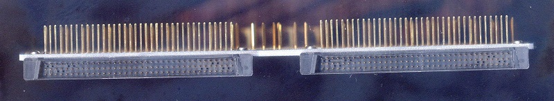
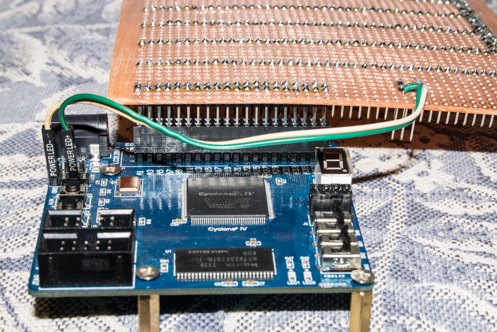
My project consists of two boards: the board on which the FPGA chip is located and the expansion board for it is a synthesizer. The boards are connected via a 40 pin connector with a loop. Then I made the whole circuit on the expansion board by surface mounting. That is, the wires were soldered directly to the connector pins. And in order to go to the installation wrap, I need to bring these 40 lines to the side of the board, where the pins will be. There, for example, I bring out, let's say 8 resistors of 10 KΩ each. I do as I decided earlier. I insert the rack into the board. From above, I solder radio elements to the racks. In the case of the connector had to solder the wires. Everything turned out very bad: for a long time, not reliably, not convenient, not beautiful. In addition, the racks were very bad, and it was very difficult to solder to them.
Top pins to go to Wire Wrap. Under them razme. And 20 bagels - wire. Below 8 resistors soldered to racks
The same - on the other hand: the top row - racks of the plug, below - two rows of racks to which resistors are soldered
Having spent 3 hours and having done only half of the work, I just went to bed with something like soldering 8 resistors, with sad thoughts.
There were two thoughts:
1) I do not properly install the elements
2) you need to solve something so that the racks are badly flooded
And before bedtime enlightenment descended on me!
Concept board
Ready Wire Wrap cards are usually made on this principle.
On the one hand, the elements are set
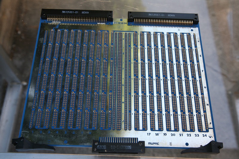
And on the other hand it all comes out with pins
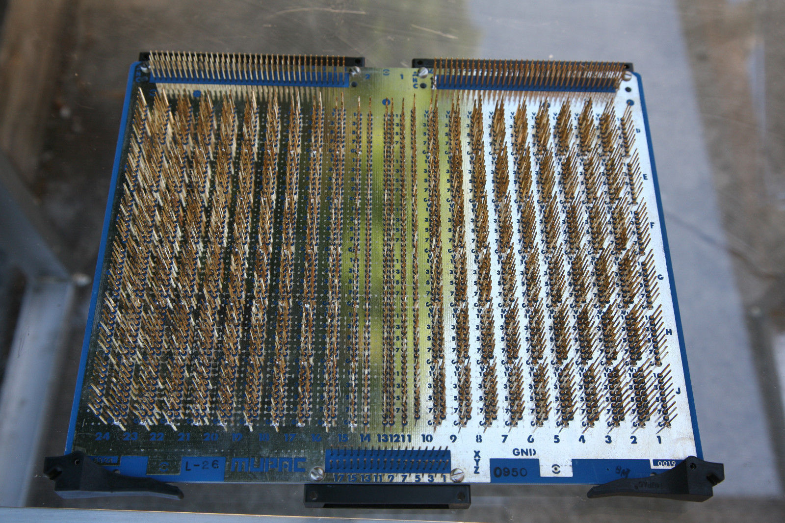
Long pins. And besides the pins on the other side there is nothing at all.
And why don't I do that? Why do I thread the racks, never fix them, but solder the radio elements on the racks?
This is nonsense! Radio elements need to be soldered just on the breadboard as usual, and the pins to the other side, where there are no copper conductors!
It remains only to solve the problem of tinning. The question was solved with the help of 38 flux. I don’t understand how I used to live without him!
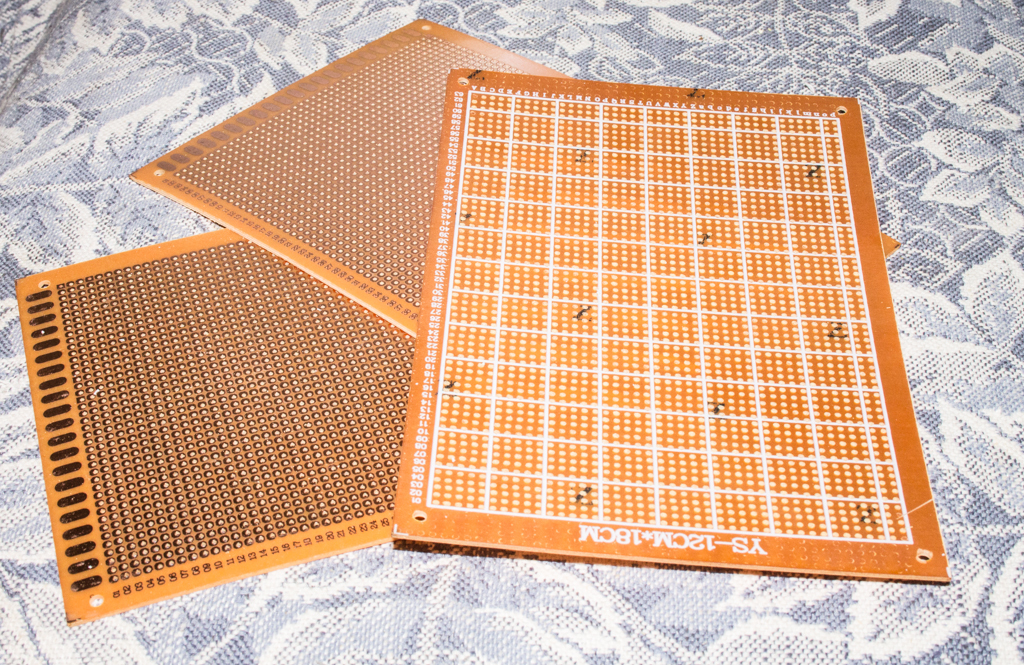
We do!
Take the curves of Chinese boards:
Racks
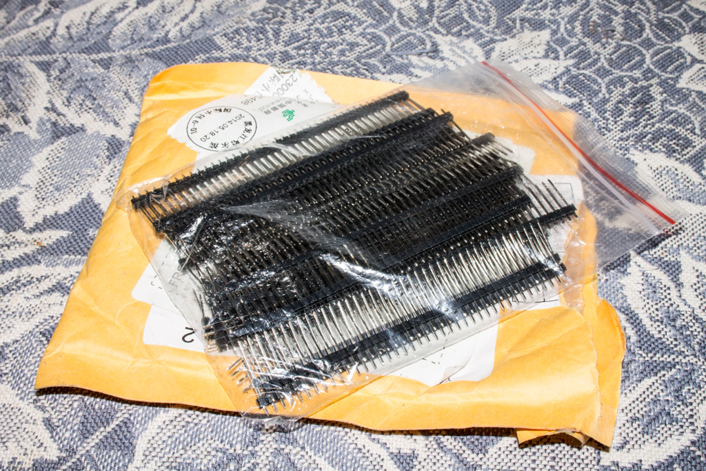
A soldering iron (I have a car 12 volt with a charger from the same place), the third hand, my favorite solder is POS-61 1.5mm two meters, and the opening of this fall is F38N, there is also a thin tube in which I took on acid and applied it to racks.

We cut off the excess from the board, skins, degrease. Ludim rack. Install on board and solder. Thanks to the flux and the POS-61 in the coil, soldering was a pleasure! Fast and beautiful.
From the end of the board I make two strips of 20 racks. This is a connector for connecting to the FPGA board. There are also two wires - power.
The rest of the mounting on the board is solely for the prototyping of the circuit I need.
From the side of printed wiring, we will solder discrete elements: microcircuits, resistors, capacitors and in the same place connect them to one of the racks. Better yet, solder the panels and insert all the elements quickly.
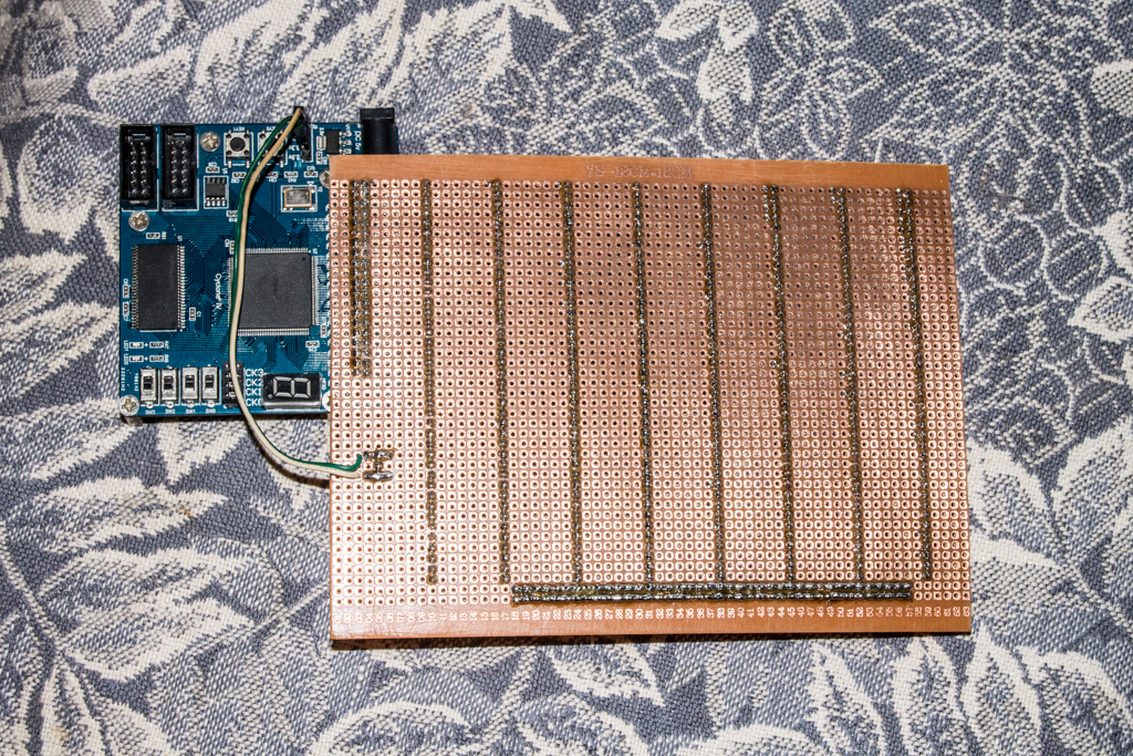
On the other hand, we already combine elements by wrap (the two lines on the right are food).

IMPORTANT MOMENT!
When switching to assembly by wrap, you need to slightly switch your thinking and start doing exactly the installation by wrap. Avoid surface mounting and, if possible, solder. I did not do it the first time. And now, when I made a new board, I almost started to make the same mistakes again. Here is an example: you need to transfer all 40 lines from the input-connector to the first line of racks. What am I going to do? Of course! Solder the wire from the connector to the first line. But this is a mistake. So do not need to. In general, you do not need to transfer all 40 lines. We need only those that are required in this scheme (1) . And instead of soldering, we can apply the installation of wrap. Racks are large, after installing the cable under it there is enough space to wind the wire (2).
(A few days later).
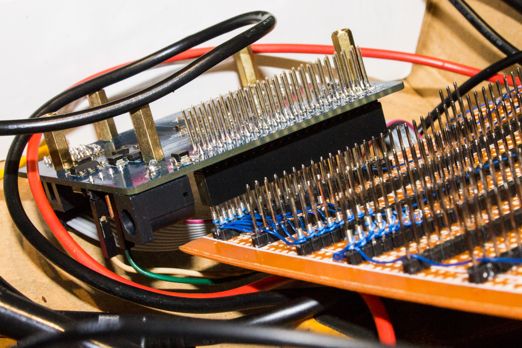
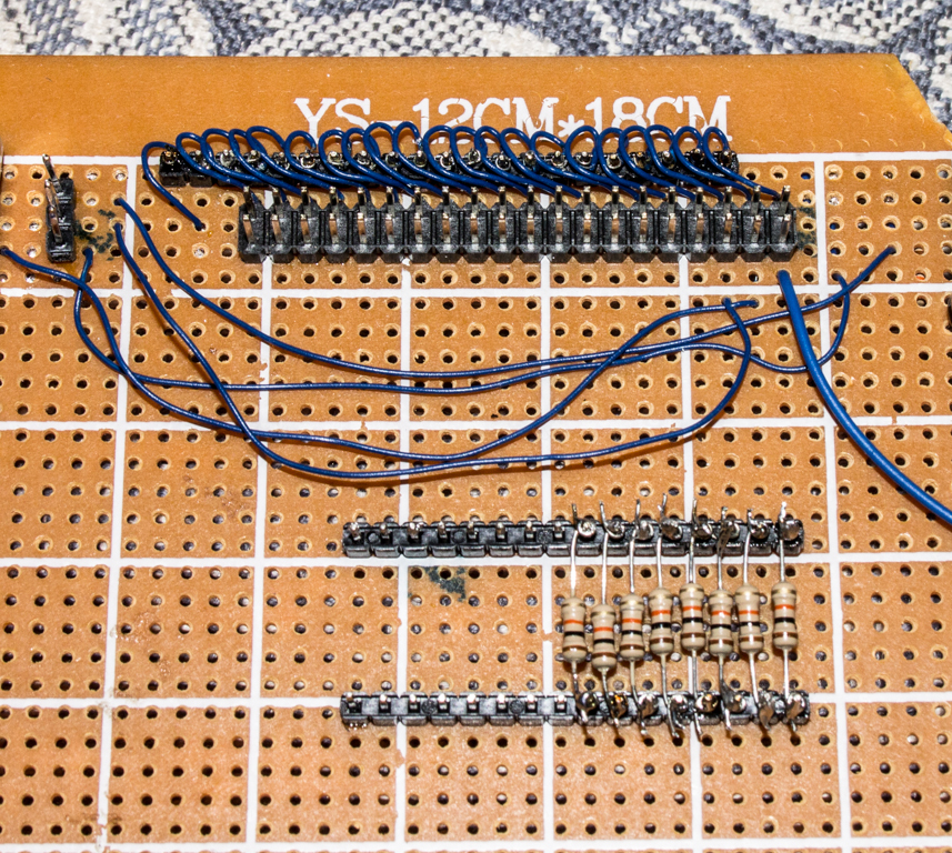
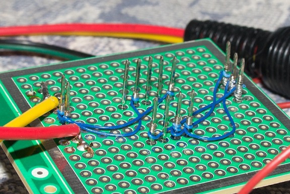
So now looks like a fee. During these days, it changed several times, but all changes were made quickly and easily.
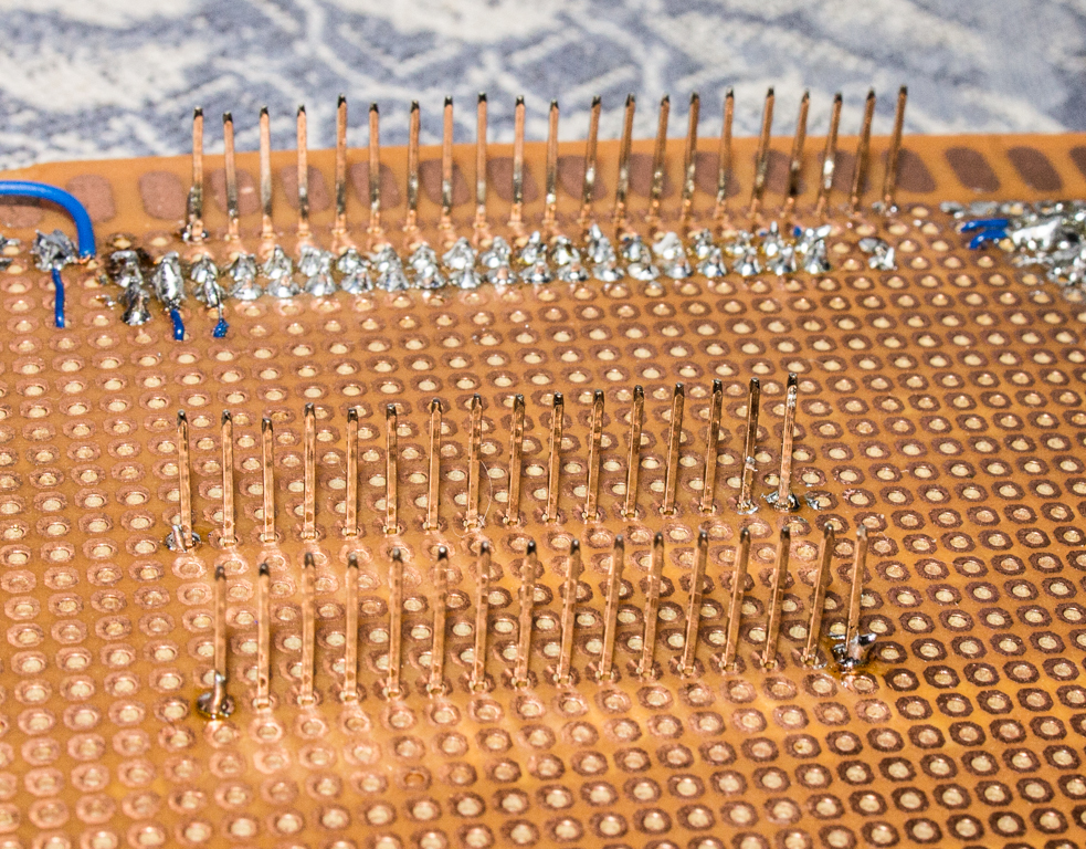
View from the side of assembly by wrap:

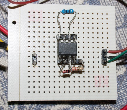
View from the side of mounting the elements (sorry, that is so motley):

Conclusion. This way of modeling suits me and I will use it in the future. Try it!
Source: https://habr.com/ru/post/240077/
All Articles